


1985 coolant sensor issue

Thread Starter
Intermediate

Joined: Jul 2010
Posts: 26
Likes: 0
From: Norfolk Virginia
Ok following the manual to the best of my abilities this is where I am at but it isn't quite jiving to me. 
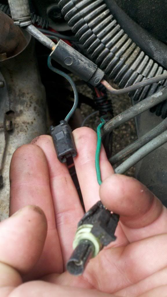
This is the sensor I was givin at car quest with a double ended pigtail to connect it up.
But I have found these two connectors coming out of the loom for the starter wires. The male connector is solid green white and the female connector is green.
Then at one point some one must of tried over riding the relay and the connector just dead ends over here.
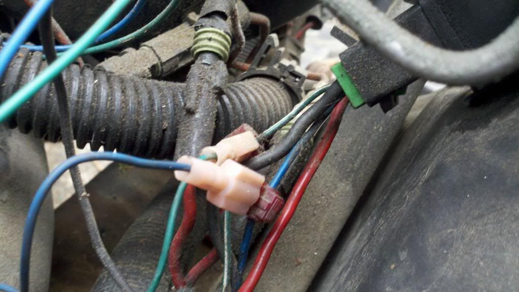
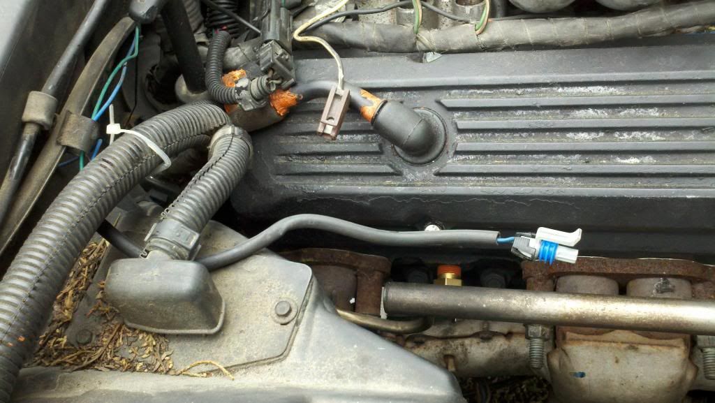
So I have this sensor going into the left passenger side because I found a dead green wire coming out of the starter loom. Which I imagined is for the coolant fan switch.
Ive read enough to know if I get them wrong I will get false temperature indications and my fans might not even work.
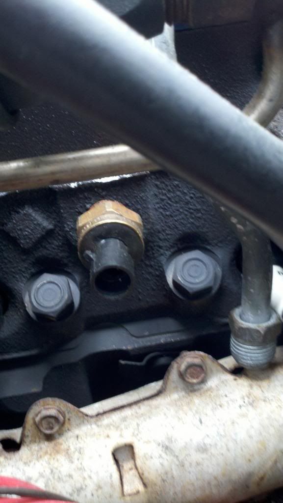
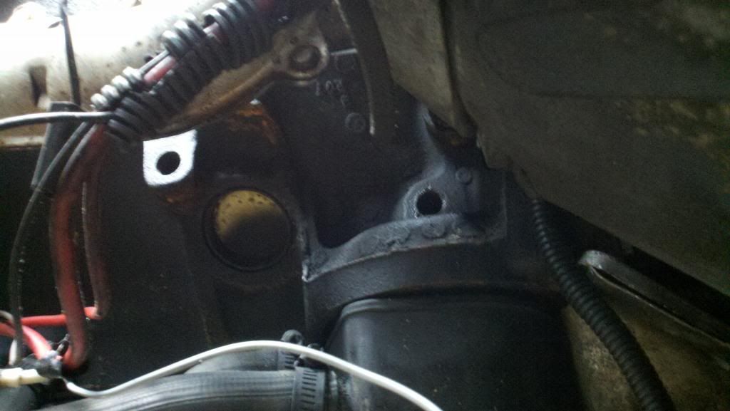
Oh on a side note I didn't know if there is something that is suppost to be in these two holes around the oil filter.

This is the sensor I was givin at car quest with a double ended pigtail to connect it up.

But I have found these two connectors coming out of the loom for the starter wires. The male connector is solid green white and the female connector is green.

Then at one point some one must of tried over riding the relay and the connector just dead ends over here.


So I have this sensor going into the left passenger side because I found a dead green wire coming out of the starter loom. Which I imagined is for the coolant fan switch.


Ive read enough to know if I get them wrong I will get false temperature indications and my fans might not even work.
Oh on a side note I didn't know if there is something that is suppost to be in these two holes around the oil filter.

Melting Slicks


Joined: Mar 2008
Posts: 2,141
Likes: 76
From: Santa Maria, CA
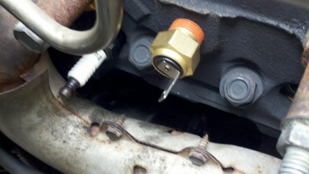
The sensor between #1 and #3 cylinders is for the dash gauge. It has a single wire blade connector. The coolant sensor for the ECM is located on the front of the intake manifold. It has a 2 wire connector. The sensor located between #6 and #8 cylinders is the fan switch. It is a single round pin. It looks like yours might have been modified to turn on both fans. That's a common change.
Thread Starter
Intermediate
Joined: Jul 2010
Posts: 26
Likes: 0
From: Norfolk Virginia
ok so the single blade sensor goes on the driver side and one of the two green wires should go to it. Then On the passenger side between 8 and 6 I am looking for the sensor that has a connector like the knock sensor. So probably what I have right now in cylinder 1 and 3 is the ecm sensor.
Melting Slicks
Joined: Mar 2008
Posts: 2,141
Likes: 76
From: Santa Maria, CA
ok so the single blade sensor goes on the driver side and one of the two green wires should go to it. Then On the passenger side between 8 and 6 I am looking for the sensor that has a connector like the knock sensor. So probably what I have right now in cylinder 1 and 3 is the ecm sensor.
Drifting

Joined: Aug 2010
Posts: 1,704
Likes: 8
Hi Booncky,at the end you have a shop manual...good
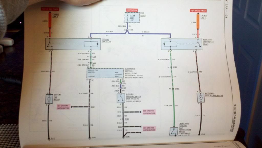
the dark blu wire and the green white are a 12 v and ground to energize relais and close the 12v supply to the fan motors as you can see from the schematics.This is the dual fan schematic.
the main fan is operated via ECM,in the tune there is a scalar for fan enamble temperature,the ECM uses the coolant sensor on the front of intake manifold to "read" the temperature,when it reaches the temp in the tune the driver inside the ECM feed the ground using the green white wire,this energizes the cooling fan relay ,it closes giving 12 v to the main fan motor( left part in your schematic).
Auxiliary fan motor is operated by auxliary fan relay ,but here the ground is feed to relay from the auxiliary temperature switch,again it energizes the relay,it gives 12 v to auxiliary fan motor,and it starts
quote "It looks like yours might have been modified to turn on both fans. That's a common change."
yep,they are using main relay to run both fans,the main and auxiliary...
fan switch

connector to fan switch (aftermarket)

the dark blu wire and the green white are a 12 v and ground to energize relais and close the 12v supply to the fan motors as you can see from the schematics.This is the dual fan schematic.
the main fan is operated via ECM,in the tune there is a scalar for fan enamble temperature,the ECM uses the coolant sensor on the front of intake manifold to "read" the temperature,when it reaches the temp in the tune the driver inside the ECM feed the ground using the green white wire,this energizes the cooling fan relay ,it closes giving 12 v to the main fan motor( left part in your schematic).
Auxiliary fan motor is operated by auxliary fan relay ,but here the ground is feed to relay from the auxiliary temperature switch,again it energizes the relay,it gives 12 v to auxiliary fan motor,and it starts
quote "It looks like yours might have been modified to turn on both fans. That's a common change."
yep,they are using main relay to run both fans,the main and auxiliary...
fan switch
connector to fan switch (aftermarket)
Last edited by tunedport85inject; May 6, 2013 at 02:16 AM.
Safety Car


Joined: Nov 2009
Posts: 3,971
Likes: 341
From: Adelaide South Australia
looking at this photo, the threaded hole above the oil filter housing is for the oil temp sender, there is a threaded hole above it which is an earth strap bolt, as for the hole on the left, is it a generic dipstick hole ?


Safety Car

Joined: Aug 2009
Posts: 3,745
Likes: 275
From: Melbourne, Victoria, Australia
Yes the 4 bolt block i that my 383 was built in had a dipstick hole between cyl 5 and 7. I plugged that up and used the std vette dipstick on the other side after i drilled the casting.
Thread Starter
Intermediate
Joined: Jul 2010
Posts: 26
Likes: 0
From: Norfolk Virginia
Hi Booncky,at the end you have a shop manual...good
the dark blu wire and the green white are a 12 v and ground to energize relais and close the 12v supply to the fan motors as you can see from the schematics.This is the dual fan schematic.
the main fan is operated via ECM,in the tune there is a scalar for fan enamble temperature,the ECM uses the coolant sensor on the front of intake manifold to "read" the temperature,when it reaches the temp in the tune the driver inside the ECM feed the ground using the green white wire,this energizes the cooling fan relay ,it closes giving 12 v to the main fan motor( left part in your schematic).
Auxiliary fan motor is operated by auxliary fan relay ,but here the ground is feed to relay from the auxiliary temperature switch,again it energizes the relay,it gives 12 v to auxiliary fan motor,and it starts
quote "It looks like yours might have been modified to turn on both fans. That's a common change."
yep,they are using main relay to run both fans,the main and auxiliary...
fan switch
connector to fan switch (aftermarket)
Corvette Stories
The Best of Corvette for Corvette Enthusiasts

8 Coolest Corvette Pace Cars (and Replicas) of All Time
Verdad Gallardo
Top 10 Corvette Engines RANKED by Peak Torque (70+ Years of Muscle!)
Joe Kucinski
Corvette ZR1X Will Be Pacing the Indy 500, And Could Probably Race, Too!
Verdad Gallardo
Top 10 Corvettes Coming to Mecum Indy 2026!
Brett Foote
Top 10 C9 Corvette MUST-HAVES to Fix These C8 Generation Flaws!
Michael S. Palmer
10 Revolutionary 'Corvette Firsts' Most People Don't Know
Joe Kucinski
5 Reasons to Upgrade to an LS6-Powered Corvette; 5 Reasons to Stay LT2
Michael S. Palmer
2027 Corvette vs The World: Every C8 vs Its Closest Competitor
Joe Kucinski
10 Most Common Corvette Problems of the Last 20 Years!
Joe Kucinski
Thread Starter
Intermediate
Joined: Jul 2010
Posts: 26
Likes: 0
From: Norfolk Virginia