


coolant wiring issue 1986 vette

Thread Starter
Navigator

Joined: Jul 2016
Posts: 9
Likes: 0
Working on an 86 vette project. Got this car with a carb setup I converted it back to tpi an rebuild motor. My problem is the coolant fan doesn't kick on. From what I understand there is a coolant temp switch on the front of the intake an one on the side of the drivers side head, I replaced the sensor on the intake an it's pigtail. I've got 4 wires on the drivers side intake that have been cut an I have no clue where they go. I do have a couple diagrams that I'm having trouble figuring out. So what color wire goes to this head sensor? An is it a single or a double wire plug? Is there a relay an where is it located?

Team Owner


Joined: Sep 2003
Posts: 25,394
Likes: 2,741
Working on an 86 vette project. Got this car with a carb setup I converted it back to tpi an rebuild motor. My problem is the coolant fan doesn't kick on. From what I understand there is a coolant temp switch on the front of the intake an one on the side of the drivers side head, I replaced the sensor on the intake an it's pigtail. I've got 4 wires on the drivers side intake that have been cut an I have no clue where they go. I do have a couple diagrams that I'm having trouble figuring out. So what color wire goes to this head sensor? An is it a single or a double wire plug? Is there a relay an where is it located?
Thread Starter
Navigator
Joined: Jul 2016
Posts: 9
Likes: 0
I've got a single stock fan. Yea I didn't think to mention the one in front of condenser , but yea it's hooked up. I don't have the car in front of me now. It'll be a couple days before I can pop the hood again

Melting Slicks


Joined: Aug 1999
Posts: 2,240
Likes: 42
From: Baltimore, MD USA
Connect pin A to pin B on the diagnostic connector.
Turn ignition On.
The ECM should flash any codes by blinking the service engine soon indicator.
The Main coolant fan should run.
You may hear a clicking noise which is the idle air control motor retracting which is normal.
If the fan does not come on.
Look for the Coolant Fan relay.
Should be mounted on the back side of the driver side plastic wheel well housing. Near below the brake master cylinder area.
The relay socket will have four wires going to the socket.
Heavy gauge Red wire is 12 volts hot all the time.
Heavy gauge Black/Red wire is power to the fan motor when the relay is energized.
Small gauge Dark Blue wire. From CFan fuse Hot with ignition On.
Small Dark Green/White wire. ECM grounds this wire to turn fan relay on.
With ignition On if you manually ground the Dark Green/White wire the fan should run.
The Coolant Temperature sensor mounted on the front edge of the intake manifold has two wires. A yellow wire which is 5 volts from the ECM and a Black wire which is ground.
If you connect the Yellow wire to the Black wire with a jumper wire that should signal the ECM the engine temperature is over 266F and the ECM should energize the Primary fan relay.


Last edited by Hooked on Vettes; Jul 6, 2016 at 08:14 AM.
Thread Starter
Navigator
Joined: Jul 2016
Posts: 9
Likes: 0
When I got this car I was told it was a fresh rebuild on a factory block. I ran the numbers on block an that was a lie. The motors a 98 truck block an most the wires I was able to figure out. Looks like I'm missing a fan relay and a bracket. The tpi setup cam off an 89 z28
Melting Slicks
Joined: Aug 1999
Posts: 2,240
Likes: 42
From: Baltimore, MD USA
What color are the wires on the plug of the picture you posted?
Is that the plug/socket for the fan relay?
Only thing you can do to identify any cut wires is to post the color of the wire
and where they are located.
The factory primary fan had two wires at it's plug. Black wire was grounded to the center cross brace. Black/Red wire ran up along the driver side wheel well housing to the Fan relay
.
Does the engine run?
If you short pin A to pin B on the diagnostic connector and turn the ignition On, does the Service Engine Soon bulb flash any codes?
Bubba strikes again.

Last edited by Hooked on Vettes; Jul 6, 2016 at 05:43 PM.
Thread Starter
Navigator
Joined: Jul 2016
Posts: 9
Likes: 0
That plug has brown black an white.. I just thought that might be my wiper motor wire an the one I have plugged in to wiper might be the relay ... ooops .I'm at work now I kinda took those pics real quick before work.car runs but doesn't idle very well. Hadn't had time to run the service engine codes
Corvette Stories
The Best of Corvette for Corvette Enthusiasts

Top 10 Most Expensive Corvettes Ever Sold on Bring A Trailer
Brett Foote
10 Things Every Corvette Owner Needs (2026 Edition)
Michael S. Palmer
8 Most "Only Corvette Owners Understand" Quirks and Problems
Pouria Savadkouei
10 Reasons the C6 Z06 is Still A Performance Benchmark After 20 Years
Joe Kucinski
How Much Horsepower Every Corvette Engine "LOST" in 1972
Joe Kucinski
Top 10 DOs and DON'Ts for Protecting Your Convertible Top!
Michael S. Palmer
Top 10 Most Explosive Corvettes Ever Made: Power-to-Weight Ratio Ranked!
Joe Kucinski
150 hp to 1,250 hp: Every Corvette Generation Compared by the Specs That Matter
Joe Kucinski
8 Coolest Corvette Pace Cars (and Replicas) of All Time
Verdad Gallardo
Thread Starter
Navigator
Joined: Jul 2016
Posts: 9
Likes: 0
After I dropped the motor in an wired everything else up took a few turns an fired up an idled.i ran the fan hot to go threw my 30 min break in. I know these go to the cooling just what where an what pigtail are needed oreaillys tells me I'm supposed to have things I don't have as far as colors
Melting Slicks
Joined: Aug 1999
Posts: 2,240
Likes: 42
From: Baltimore, MD USA
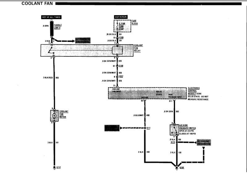
The coolant fan relay and connector pigtail are available from NAPA. Appears Advance Auto and Autozone also sell the relay or can order it.
Appears the color of the aftermarket pigtails are all the same color so you need to go by the A B C D E pinout to determine what wire goes where.
This is a picture of the connector for the coolant fan relay.

Pin A is a Black/Red wire goes to the fan motor.
Pin B is a Dark Green/White wire. ECM grounds this wire to energize the relay.
Pin C is a Dark Blue wire that provides 12 volts to the primary relay coil.
Pin D not used
Pin E Red wire passes 12 volts to the Black/Red wire for the fan motor when the relay closes.
This picture shows the pin out of the Engine Coolant temperature sensor.

Pin A is a Black wire and is sensor ground.
Pin B is a Yellow wire and is 5 volts from the ECM.
This picture shows the location of the fuel pump relay which is what the coolant fan relay looks like. The relay for the coolant fan has a higher current capacity than the fuel pump relay but they look the same and use the same connector.

Last edited by Hooked on Vettes; Jul 7, 2016 at 07:03 AM.
Thread Starter
Navigator
Joined: Jul 2016
Posts: 9
Likes: 0
The coolant fan relay and connector pigtail are available from NAPA. Appears Advance Auto and Autozone also sell the relay or can order it.
Appears the color of the aftermarket pigtails are all the same color so you need to go by the A B C D E pinout to determine what wire goes where.
This is a picture of the connector for the coolant fan relay.
Pin A is a Black/Red wire goes to the fan motor.
Pin B is a Dark Green/White wire. ECM grounds this wire to energize the relay.
Pin C is a Dark Blue wire that provides 12 volts to the primary relay coil.
Pin D not used
Pin E Red wire passes 12 volts to the Black/Red wire for the fan motor when the relay closes.
This picture shows the pin out of the Engine Coolant temperature sensor.
Pin A is a Black wire and is sensor ground.
Pin B is a Yellow wire and is 5 volts from the ECM.
This picture shows the location of the fuel pump relay which is what the coolant fan relay looks like. The relay for the coolant fan has a higher current capacity than the fuel pump relay but they look the same and use the same connector.
Melting Slicks
Joined: Aug 1999
Posts: 2,240
Likes: 42
From: Baltimore, MD USA
The one plug is for my over drive relay. So that's taken car of... so I grounded the green/White wire an still no fan. Connected my a an b on diagnostic terminal an I got one long 3 short flash that's reoccurring. Also my dash temp gauge jumps to 160 an sits my other gauge (aftermarket temp) reads 210 in the head.. still hadn't figured out where the white/black wires go or the brown or gray running loose
Should measure 12 volts on the Dark Blue wire. 12 volts comes from C Fan fuse.
Should measure 12 volts on the Red wire. 12 volts comes from a fusible link.
Ground the Dark Green/White wire.
The relay should energize and you should measure 12 volts on the Black/Red wire which powers the radiator fan.
Dash temperature gauge sender is screwed into the driver side head between the 1 and 3 spark plug. Should have a single spade lug wire either Dark Green or Blue colored wire.
Ignition On.
If you unplug the wire it should read Low.
If you ground the wire the temperature should read very High.
The ground for that sender is the engine block so if someone used teflon tape on the sender threads it could cause a bad ground.
When you shorted pin a to pin b did the Service
Engine Soon indicator blink 12 three times?
Blink pause Blink Blink long pause Blink pause Blink Blink long pause Blink pause Blink Blink. After that any codes will be displayed.
If you are saying you received a Blink pause Blink Blink Blink that indicates a code 13 which is an open oxygen sensor circuit.
White/Black is usually a ground. You can verify that with an ohm meter. Should read zero resistance from that wire to the negative battery terminal if it is a ground.
Post a picture of the Brown and Gray wire and the location of the wires.
Last edited by Hooked on Vettes; Jul 15, 2016 at 07:36 PM.