


1986 cruise control doesn´t work
Thread Starter
Racer


Joined: Oct 2007
Posts: 442
Likes: 15
From: FL
1986 AT coupe, C68. Yes, I´ve read a lot of threads on this.
Cruise never worked during the two years I´ve had the car. Here´s what I found:
I have the FSM and belive the next step might be an ohms test, but try to get around pulling the cluster again. The old plastic is brittle and breaks a little more everytime I touch the cluster cover.
Any other tests I could perform to get the system to "click"?
Cruise never worked during the two years I´ve had the car. Here´s what I found:
- Vacuum seems good, have tried with a vaccum pump.
- Have replaced the check valve.
- Hoses look good.
- HVAC air can be directed to the various vents.
- Have tested all fuses in the pass. side fuse box, all check out ok.
- Have +8V between pin B and D at the servo connector with "IGN on", lever switch to "CC on" and 0V with lever switch to "CC off". I hear NO CLICK when lever switch put to "CC on".
- Have a CC instrument cluster, I saw the electric board on the cluster when I swapped out the old (already repaired) cluster to a functional one (display was partly out). Not sure if the circuit works though.
- Can not get the CC to set when driving above 35mph and holding the pedal up wit the foot.
- FWIW: brake lights plus CHMBL come on when brakes applied.
- Throttle cable at the engine moves when depressing the diafragm at the servo.
I have the FSM and belive the next step might be an ohms test, but try to get around pulling the cluster again. The old plastic is brittle and breaks a little more everytime I touch the cluster cover.
Any other tests I could perform to get the system to "click"?
Last edited by colonel328; Mar 21, 2024 at 08:47 AM.
Racer

Joined: Mar 2020
Posts: 387
Likes: 148
From: Langton, Ontario, Canada
2025 C4 of the Year Finalist - Unmodified
There is a vacuum hose from the cruise actuator through the firewall to the brake pedal. When I checked mine, it looked good, but under vacuum, it collapsed and leaked like a sieve. I replaced all my vacuum hoses with silicone hoses. After 30+ years, they're toast.

Race Director


Joined: Aug 2000
Posts: 11,470
Likes: 764
did the same - replaced most all vacuum lines on my 85. agree, after 30 years - things like that don't last forever. got to say, everything works, car never ran better, and idles smooth as silk.
Last edited by Joe C; Mar 17, 2024 at 10:26 AM.
Thread Starter
Racer
Joined: Oct 2007
Posts: 442
Likes: 15
From: FL
Here are some results from the tests I executed:
@Vets-Vet
Below, on the left the vacuum comes in from the system, do you have vacuum at the servo waiting for the vaccum valve to open? - yes
Pins A & E on the valve get 12vdc when CC commended (yes driving), it opens the vacuum valve and closes the vent valve, what voltage do you have on pins A & E at the servo (each to ground, not to each other) ??
Pin A: IGN on, CC off: 26,5 mV
Pin E: IGN on, CC off: 26.5 mV
Pin A: IGN on, CC on: 62-67 mV
Pin E: IGN on, CC on: 62-67 mV
Check the ground in the left front wheel well area on the frame near the horn. - near the horn, but closer to the front of the vehicle: looked ok, took it off anyways, cleaned and re-installed it
When you apply vacuum to the the release line, does it pass air continuously or can you draw a vacuum on it ? I can pull a vac with a vacuum pump and it holds good. It does immediately drop to zero when brake pedal is depressed
More tests:
a) Any idea how to repair the servo or what else to check?
b) Are 62-67 mV at Pin A & E ok or should I see +12V with the vehicle sittting? Do the transistors in the IP control the voltage (+12V maybe?) from a certain speed?
@Vets-Vet
Below, on the left the vacuum comes in from the system, do you have vacuum at the servo waiting for the vaccum valve to open? - yes
Pins A & E on the valve get 12vdc when CC commended (yes driving), it opens the vacuum valve and closes the vent valve, what voltage do you have on pins A & E at the servo (each to ground, not to each other) ??
Pin A: IGN on, CC off: 26,5 mV
Pin E: IGN on, CC off: 26.5 mV
Pin A: IGN on, CC on: 62-67 mV
Pin E: IGN on, CC on: 62-67 mV
Check the ground in the left front wheel well area on the frame near the horn. - near the horn, but closer to the front of the vehicle: looked ok, took it off anyways, cleaned and re-installed it
When you apply vacuum to the the release line, does it pass air continuously or can you draw a vacuum on it ? I can pull a vac with a vacuum pump and it holds good. It does immediately drop to zero when brake pedal is depressed
More tests:
- Vacuum at the supply line with engine running at idle is 18" (spec: 15-20")
- ohms check at the servo Pins: A+C is 39,8 (spec: 30-50 ohms), C+E is 39,1 (spec: 30-50 ohms), B+D is 19,3 (spec: 10-30 ohms)
- Volts between Pin B+D at the servo w/IGN on, CC on is 8V (spec: 8V)
- both hose ends at the servo look good, so do the hoses to the firewall and to the vac reservoir in the front (also to the check valve)
- IGN on, CC on: NO click or movement on the servo
- servo on the bench, housing off: internals look good, plunger and pin move freely, no disintegrated foam, no lose hair wires
- servo on the bench, external +12V to Pin A and GRND to Pin C, 15" external vacuum: servo clicks. Then jumper between Pin E and GRND: nothing (accoring to FSM, table 3, vacuum should pull servo in all the way)
- as 6, but w/both ports plugged: same result
a) Any idea how to repair the servo or what else to check?
b) Are 62-67 mV at Pin A & E ok or should I see +12V with the vehicle sittting? Do the transistors in the IP control the voltage (+12V maybe?) from a certain speed?
Thread Starter
Racer
Joined: Oct 2007
Posts: 442
Likes: 15
From: FL
Vets-Vet said:
You are saying that 12v on pin E and ground on pin C and you get no click ??
I did say that, but my setup was wrong, must have gotten confused: I jumpered E to GRND, which didn´t produce anything. I now re-tested on the car and got clicks with +12V to A as well as to E. With +12V to A and the diafragm depressed, the vaccum holds. So the servo seems ok.
Vets-Vet said:
I do not have a cruise so what speed it sets I am unsure. I would imagine it has a minimum speed.
The cruise is supposed to set at 25 or 35 mph, according to various sources. I tend to say at above 25 mph.
Vets-Vet said:
I would also imagine the 12vdc at A & E are the commands to turn on.
I agree.
Vets-Vet said:
You can test this by turning off the CC while driving at observe the voltage.
Will try.
Vets-Vet said:
You can test the coils in the solenoids by ohming them from pin A to C and from pin E to C. Since you know the vent valve clicks, it is a known good solenoid so the measurement from pin E to pin C should by nearly identical to A to C.
I pulled out my servo from my parts box and measured 40.8 ohms from E to ground and A to ground (pin C) .
Pls see my ohms reading in post #6, just under 40 ohms (within specs)
Vets-Vet said:
""Then jumper between Pin E and GRND: nothing"" Can you clarify this statement? Pin E should get voltage just like pin A.
Yeah, my bad.
In a nutshell, the servo seems to do what it is supposed to. I just don´t seem to get +12V on Pin A and Pin E while trying to turn the CC on. Does the CC circuit board in the IP control this? If so, my transistors may be shot.
Thread Starter
Racer
Joined: Oct 2007
Posts: 442
Likes: 15
From: FL
All three fuses are good. The only fuse/wires that seem to be bad is the 3A ECM fuse (well, the fuse is good, but no voltage on the pins).
I have yet to check continuity on the stalk and it’s wires.
I have yet to check continuity on the stalk and it’s wires.
Corvette Stories
The Best of Corvette for Corvette Enthusiasts

Top 10 Most Expensive Corvettes Ever Sold on Bring A Trailer
Brett Foote
10 Things Every Corvette Owner Needs (2026 Edition)
Michael S. Palmer
8 Most "Only Corvette Owners Understand" Quirks and Problems
Pouria Savadkouei
10 Reasons the C6 Z06 is Still A Performance Benchmark After 20 Years
Joe Kucinski
How Much Horsepower Every Corvette Engine "LOST" in 1972
Joe Kucinski
Top 10 DOs and DON'Ts for Protecting Your Convertible Top!
Michael S. Palmer
Top 10 Most Explosive Corvettes Ever Made: Power-to-Weight Ratio Ranked!
Joe Kucinski
150 hp to 1,250 hp: Every Corvette Generation Compared by the Specs That Matter
Joe Kucinski
8 Coolest Corvette Pace Cars (and Replicas) of All Time
Verdad GallardoBurning Brakes


Joined: Jun 2022
Posts: 845
Likes: 212
From: Florida
I had done all the diagnostic work you did, including the replacement of the two vacuum hoses from the CC and it still would not work. Upon further research, I found an old post where a member either replaced or cleaned all of his switches. I decided to remove all 3 (for a manual car) and upon closer inspection, I found out one of the switches stayed engaged (making contact) all the time. I believe it was the brake switch. In other words, the CC saw the brake pedal depressed all the time, so it was not able to engage.
I took the switch apart and bent the contacts so they would disengage. My CC started working again normaly.
Ric
EDIT: Found pictures from the time I worked on the CC.


Looking up at the brake and clutch pedals.

The switches are very easy to pry open and have just a few components inside.
Last edited by rremesal; Mar 19, 2024 at 01:42 PM.

Burning Brakes

Joined: Oct 2017
Posts: 823
Likes: 106
From: Somewhere near Fort Wayne, Indiana
The CC circuit is in the instrument panel. In my 89, I had tested everything, ended up replacing the solenoids in the servo (swapped out from a junkyard unit) and then had to replace the CC transistors in the IP. Batee sells them, and has instructions how to do the job.

Pro

Joined: May 2017
Posts: 583
Likes: 196
From: Wisconsin
A long shot but.......
Check and make sure you have all three mounting bolts, rubber inserts and metal sleeves intact and secured that hold the servo onto the bracket. The car I was working on a 1986 was missing one and when replaced it corrected the problem of the cruise not engaging.
Lots of good info posted by others above for you to check also.
Good luck I hope this helps.
Thread Starter
Racer
Joined: Oct 2007
Posts: 442
Likes: 15
From: FL
Here are 3 basic checks before going to or blaming the cluster.
Servo:
You need some alligator-clip test leads. Remove the connector at the transducer.
Connect C to Ground.
Put a jumper on A and E. Briefly touch each to B+, there should be an audible 'click'.
Start engine. Connect A to B+. Nothing should happen.
Briefly touch E to B+ in small pulses. The servo should pull-in, increasing the throttle and engine speed. The servo should hold the setting when E is disconnected.
Remove A from B+, servo should return to idle.
If any of the above don't pass, check vacuum source, vacuum switch on pedal. If the servo bleeds off (doesn't hold position when E is disconnected) the internal servo valves may be leaking.
~~~~~~~~~~~~~~~~~~~~~~~~~~~~~~~~~~~~~~~~
Multifunction Lever:
Gain access to connector at base of steering column. The stalk connector has 4 wires, and the switch side looks like a little circuit board. (I'm using the schematic from my 1985 FSM, the wire colors may be different, but you should be able to test and confirm the 3 outputs.
With key in RUN, check the following for voltage to GROUND.
switch side / car side
Lt Blue / Pink/Black HOT with key in RUN
Green / Dk Blue With switch in ON.
Red / Dk Blue with SET pushed
Yellow / Dk Green in RESUME.
~~~~~~~~~~~~~~~~~~~~~~~~~~~~~~~~~~~~~
Brake and Clutch switches:
With key in RUN, and stalk switch in ON. Pedal(s) at rest.
There should be voltage on ALL the dk blue, and gray or gray/blk wires. (I've seen both color wires at the cruise pedal switches. Gray or gray/blk, if they are on the pedal switches, they are the cruise "disengage" input.)
In a 4+3 car, the brake switch is before the clutch switch. Pushing the brake should remove the voltage from both clutch switch gray wires. Pushing the clutch switch should remove the voltage from one of the gray wires.
~~~~~~~~~~~~~~~~~~~~~~~~~~~~~~~~~~~~~~
I took the CC pedal switch out and checked for continuity on the bench. I could not find any, neither with the plunger out nor in. I took the switch apart, re-bend the tangs a tad, removed a little dirt at the vacuum port and pin and put everything back together. Now I have continuity with the plunger depressed and no continuity with plunger out. Put it back on the car, did a test drive: still no CC.
Checked once more for continuity, now with the switch on the car: continuity from one pin to the other at the switch, with the pedal at rest, no continuity with the brake pedal depressed. Is this as it should be?
Not sure if I seated the switch correctly: before I worked on it, the plunger never bottomed out, it was always against the brake pedal lever. Now when the brake pedal is depressed, the plunger bottoms out and there´s a gap between the plastic plunger and the metal plate (as is with the brake light switch).
Would I be right to assume that everything works as it should from what I wrote above and I now needes to move on to the IP connector?
Last edited by colonel328; Mar 20, 2024 at 08:30 AM.
Thread Starter
Racer
Joined: Oct 2007
Posts: 442
Likes: 15
From: FL
A long shot but.......
Check and make sure you have all three mounting bolts, rubber inserts and metal sleeves intact and secured that hold the servo onto the bracket. The car I was working on a 1986 was missing one and when replaced it corrected the problem of the cruise not engaging.
Lots of good info posted by others above for you to check also.
Good luck I hope this helps.
Check and make sure you have all three mounting bolts, rubber inserts and metal sleeves intact and secured that hold the servo onto the bracket. The car I was working on a 1986 was missing one and when replaced it corrected the problem of the cruise not engaging.
Lots of good info posted by others above for you to check also.
Good luck I hope this helps.
Pro
Joined: May 2017
Posts: 583
Likes: 196
From: Wisconsin
There are three mounting points. Each has three pieces. 1 bolt, 1 rubber insert and 1 metal sleeve/bushing. The issue with the one I was working on was missing all three pieces for one of the mounting points so the servo was being held in place by only 2 mounting points instead of three. I spent a lot of time tracking things down to figure out the problem and this is what I found and corrected the issue. I was surprised that was the problem. Lots of hours I spent and finally was such a simple fix for me.
Thread Starter
Racer
Joined: Oct 2007
Posts: 442
Likes: 15
From: FL
Will see to get it fixed and remove the wobbeling. However, it sounds as if this would only be a question of adjusting the CC, not getting it to engage at all. Will look into this anyways, thx.
Last edited by colonel328; Mar 20, 2024 at 03:02 AM.
Pro
Joined: May 2017
Posts: 583
Likes: 196
From: Wisconsin
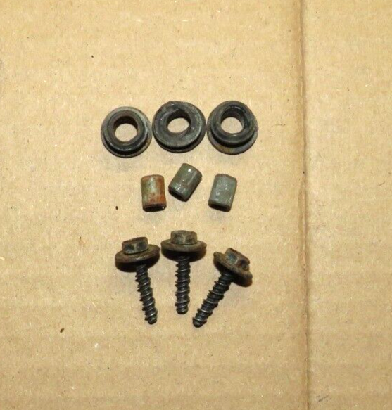
It must be important to have the correct mounting hardware pieces. Below is a picture of the three pieces needed for each mounting location. I found this image on ebay. There are quite a few for sale there. These were used from 1984-1996 and maybe on other GM vehicles that you maybe could find in a junk yard.
Link to diagram of parts: https://chevrolet.7zap.com/en/corvet...623551623-0-0/
These are the GM NUMBERS 14091274 14091273 11514270
This is what I used for a search on ebay: "1984-1996 Corvette Cruise Control Servo Mounting"
Good luck and don't give up.
Link to diagram of parts: https://chevrolet.7zap.com/en/corvet...623551623-0-0/
These are the GM NUMBERS 14091274 14091273 11514270
This is what I used for a search on ebay: "1984-1996 Corvette Cruise Control Servo Mounting"
Good luck and don't give up.
Last edited by JETS C3-C4; Mar 20, 2024 at 12:33 PM.
Thread Starter
Racer
Joined: Oct 2007
Posts: 442
Likes: 15
From: FL
Originally Posted by IHBD;[url=tel:1607638630
1607638630]Those are not the Cruise Control Disengage wires/circuit! (Those are for the Transmission Converter Clutch. Pnk/blk is hot with key in RUN, purple is hot with pedal not depressed.
I think I know where the confusion is:
In an automatic car, the TCC wiring is on the switch with the CC vacuum hose on it. The gray Cruise Control wires are on the other switch with the brake lights. So both switches have functions for CC. (Why they do it this way, I have no idea. But they do.)
Re-check the gray wires.
Is how I adjusted the switch correct?
Thread Starter
Racer
Joined: Oct 2007
Posts: 442
Likes: 15
From: FL
And did you ever get the CC to work?
Thread Starter
Racer
Joined: Oct 2007
Posts: 442
Likes: 15
From: FL
Yes. Applying the brake opens the circuit. (For both the cruise and the TCC.)
This is correct.
And as an FYI: Be sure you have the TCC switch adjusted and functioning correctly. TCC provides a significant improvement in fuel economy. You want TCC to be applied when it is supposed to be. Above 38-ish MPH, IIRC for a Corvette.
This is correct.
And as an FYI: Be sure you have the TCC switch adjusted and functioning correctly. TCC provides a significant improvement in fuel economy. You want TCC to be applied when it is supposed to be. Above 38-ish MPH, IIRC for a Corvette.
Can I feel if TCC applies? Like significant reduction in RPMs? My fuel economy improved a lot during recent weeks since I undid the battery and after re-connecting, driving the interstate for a coupla hundred miles. I was thinking the ECM re-learned and adjusted fuel injection according to my driving. I may have to push the TCC switch in a little further to make sure.
Last edited by colonel328; Mar 21, 2024 at 06:05 AM.
Thread Starter
Racer
Joined: Oct 2007
Posts: 442
Likes: 15
From: FL
Pretty simple test, although in a lightweight car like the C4, the difference between applied and released may be subtle. You'll have to try it a few times to be convinced that it is applying/releasing.
The TCC releases whenever the brake pedal is applied.
Drive along at 50-60 MPH, steady state, 4th gear, throttle not at zero.
Keep the throttle steady. With your left foot apply the brake enough to open the switch, but not enough to apply the brakes. Watch the tach and listen to the exhaust note. When the clutch releases there should be a slight (100-200max RPM) increase in engine RPM. When you release the pedal, after a short pause, the RPM should go back to where it was.
I've only owned one automatic C4, sold 27 years ago, and I vaguely recall that it was difficult to discern the TCC apply and release because the car was so light that there isn't much reduction in RPM because the torque converter doesn't slip much when lightly loaded. Not like a pick up truck or Suburban which is heavy enough to cause the converter to slip more when unlocked. When the converter locks in a heavy truck, the RPM drop is more defined, and easialy detected that it occurred.
~~~~~~~~~~~~~~~~~~~~~~~~~~~~~~~~~~~~~~~~ ~~~~~~~~~~~~~~~~~~~~~~~~~~~~~~~~~~~~~~~~ ~
If you really want to know what the TCC is doing, you can rig a temporary indicator light you can watch from the driver seat.
Use an incandescent light bulb like a 194. Wire it between ALDL cavities A and F (Top row, outboard-most cavities.).
Cavity F is the ECM control side of the TCC solenoid. When the TCC is released, Cavity F is at 12V potential. A is Ground, so the light is ON. When ECM commands TCC=ON, Cavity F is pulled to 0-volts. The light is OFF.
Go for a drive.
Keep in mind that the TCC is released anytime the brake is applied. The light will be OFF with brake applied. Just Ignore the light if you have the brake applied.
When the light is ON, the TCC is RELEASED.
When the light is OFF, the TCC is APPLIED.
Accelerate gently and you should see the light go OFF, and detect a slight reduction in RPM at around 38-40 MPH. Add throttle, and the trans may downshift, or the ECM may just release the TCC (light comes ON). Lift the throttle, and the ECM should re-apply the TCC. (Light goes OFF.)
EDIT/ADD: I forgot. The TCC is released at zero-throttle. Ie, when you take your foot off the throttle, the TCC is released. (Light comes ON.) Reapply throttle, and if conditions are met, the TCC is re-applied. (Light goes OFF.)
This will confirm that the electrical portion of the TCC system is functioning properly. There can still be mechanical maladies within the transmission affecting the actual clutch application, but with the light you can verify that the control is working, and know when to listen/'feel' for the RPM change.
Last edited by colonel328; Mar 21, 2024 at 05:25 AM.