Rear Gear Ratio
 12-03-2011, 01:09 PM
#1
Burning Brakes

Thread Starter
Member Since: Jan 2006
Location: Clear Lake Shores Texas
Posts: 988
Received 263 Likes
on
184 Posts
2016 C3 of Year Finalist

I'm still new to the ZR1 world and trying to figure out a few things about my '90. The car is turning about 1750 RPM at 60 MPH in 6th gear and about 2000 at 70. This leads me to believe it does not have the 3.45 rear gear. I did check the speedo with my GPS and it was dead on. Does this sound like 4.10's?
Thanks.
Thanks.
Last edited by dan1495; 12-03-2011 at 01:24 PM. Reason: tYPO
 12-03-2011, 01:33 PM
#2
Le Mans Master

Member Since: Oct 2004
Location: South-central Missouri
Posts: 6,314
Received 500 Likes
on
395 Posts
I'm still new to the ZR1 world and trying to figure out a few things about my '90. THE car is turning about 1750 RPM at 60 MPH in 6th gear and about 2000 at 70. This leads me to believe it does not have the 3.45 rear gear. I did check the speedo with my GPS and it was dead on. Does this sound like 4.10's?
Thanks.
Thanks.
Your speedo might be correct, but it is common for the printed resistor on a ceramic substrate to deteriorate over time, resulting in the tach reading high. (Mine reads almost 20% high. Sorta freaks some passengers out when I don't shift before the tach passes 8000!
 )
)There was a thread on this a year or so ago, complete with pictures, etc, as to what needs to be done, along with some resistance values, depending on MY.
If you can't find it (the info) get back and I'll dig it up for ya. (I seem to recall putting the info in a "safe place" where I wouldn't loose it...You know the rest
 )
)If you have a scanner, you can compare the actual reading from that ALDL connector to the tach. Then you'll have an idea of what the real reading is.
I set my shift light according to the scanner. As for the tach reading, well, it's just relative, for now. As long as I have the shift light and know what the error is, I can get by until winter comes along and I'm bored for something to do!
P.
12-05-2011, 09:35 AM
#4
Racer


So Paul, does this mean that, even when the tach is incorrect, the actual rpm is still being transmitted to the ECM, so that the engine operates with the correct info?

 12-11-2011, 04:10 AM
#6
Le Mans Master
Member Since: Oct 2004
Location: South-central Missouri
Posts: 6,314
Received 500 Likes
on
395 Posts
**FSM Electrical, pp 8A-22-8
Note: If you install a (Raptor) shift light, the light uses the same signal source (E1 - a white wire - on the C100 connector) as the tach, but operates independently from the tach. SO! you can use a scanner to reference the rpm signal at the ALDL connector to check the shift light setting.
Having the shift light there - which has no hysteresis errors (as does the tach - especially in first and second gears) - tends to marginalize the tach error importance...until it is convenient to deal with it.
Having the shift light there - which has no hysteresis errors (as does the tach - especially in first and second gears) - tends to marginalize the tach error importance...until it is convenient to deal with it.
Hope this helps.
P.
12-11-2011, 04:28 AM
#7
Le Mans Master
Member Since: Oct 2004
Location: South-central Missouri
Posts: 6,314
Received 500 Likes
on
395 Posts
P.
12-11-2011, 06:50 PM
#8
Racer
Member Since: Nov 2004
Location: Sacramento CA.
Posts: 312
Likes: 0
Received 0 Likes
on
0 Posts
Is this what has been mentioned? Found it on another board.
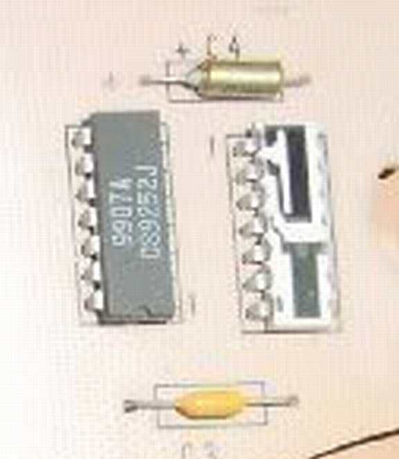
Hi, this is a 90 circuit board, see Capacitors number C3 and C4, between them is the IC CS9252 black part, and the white part with the black etching on it, this is the problem part. GM used a laser beam to calibrate it. If you look close you'll see a very thin 1/4 long line. this is the calibration. What happening is that black carbon is deteriorating and the more it does the more it reads higher .To fix the problem, you need to get some 1/4 watt resistors, 100,000 Ohms, or 100 K, 250,000,or 250 K and 500,000 or 500 K ohms.,. ( Radio Shack ) What you need to do is piggy back the resistor or maybe a combination of resistors onto Capacitor C-4, the gold color one . I would start with a 250,000 ohm or 500,000 ohm resistor,.this will bring it down about 1 , to 1 1/2 inches .This is trial and error method I have a tested it easy. So let say you went too low now, now you add 100,000 more, this will bring it back up a little. Get the picture the less you add the more it goes down lower, the more the higher up it goes. If you play with it you'll see. You really need some equipment to get it perfect, but you should get pretty close this way.
Hi, this is a 90 circuit board, see Capacitors number C3 and C4, between them is the IC CS9252 black part, and the white part with the black etching on it, this is the problem part. GM used a laser beam to calibrate it. If you look close you'll see a very thin 1/4 long line. this is the calibration. What happening is that black carbon is deteriorating and the more it does the more it reads higher .To fix the problem, you need to get some 1/4 watt resistors, 100,000 Ohms, or 100 K, 250,000,or 250 K and 500,000 or 500 K ohms.,. ( Radio Shack ) What you need to do is piggy back the resistor or maybe a combination of resistors onto Capacitor C-4, the gold color one . I would start with a 250,000 ohm or 500,000 ohm resistor,.this will bring it down about 1 , to 1 1/2 inches .This is trial and error method I have a tested it easy. So let say you went too low now, now you add 100,000 more, this will bring it back up a little. Get the picture the less you add the more it goes down lower, the more the higher up it goes. If you play with it you'll see. You really need some equipment to get it perfect, but you should get pretty close this way.
12-12-2011, 06:22 AM
#9
Le Mans Master
Member Since: Oct 2004
Location: South-central Missouri
Posts: 6,314
Received 500 Likes
on
395 Posts
Is this what has been mentioned? Found it on another board.
Hi, this is a 90 circuit board, see Capacitors number C3 and C4, between them is the IC CS9252 black part, and the white part with the black etching on it, this is the problem part. GM used a laser beam to calibrate it. If you look close you'll see a very thin 1/4 long line. this is the calibration. What happening is that black carbon is deteriorating and the more it does the more it reads higher .To fix the problem, you need to get some 1/4 watt resistors, 100,000 Ohms, or 100 K, 250,000,or 250 K and 500,000 or 500 K ohms.,. ( Radio Shack ) What you need to do is piggy back the resistor or maybe a combination of resistors onto Capacitor C-4, the gold color one . I would start with a 250,000 ohm or 500,000 ohm resistor,.this will bring it down about 1 , to 1 1/2 inches .This is trial and error method I have a tested it easy. So let say you went too low now, now you add 100,000 more, this will bring it back up a little. Get the picture the less you add the more it goes down lower, the more the higher up it goes. If you play with it you'll see. You really need some equipment to get it perfect, but you should get pretty close this way.
Hi, this is a 90 circuit board, see Capacitors number C3 and C4, between them is the IC CS9252 black part, and the white part with the black etching on it, this is the problem part. GM used a laser beam to calibrate it. If you look close you'll see a very thin 1/4 long line. this is the calibration. What happening is that black carbon is deteriorating and the more it does the more it reads higher .To fix the problem, you need to get some 1/4 watt resistors, 100,000 Ohms, or 100 K, 250,000,or 250 K and 500,000 or 500 K ohms.,. ( Radio Shack ) What you need to do is piggy back the resistor or maybe a combination of resistors onto Capacitor C-4, the gold color one . I would start with a 250,000 ohm or 500,000 ohm resistor,.this will bring it down about 1 , to 1 1/2 inches .This is trial and error method I have a tested it easy. So let say you went too low now, now you add 100,000 more, this will bring it back up a little. Get the picture the less you add the more it goes down lower, the more the higher up it goes. If you play with it you'll see. You really need some equipment to get it perfect, but you should get pretty close this way.

A couple things:
- By temporarily installing a variable potentiometer ("pot") first, you could dial in the calibration. Then by removing the pot and reading the resistance that resulted in the calibrated value, a fixed resistor of that attained value could be installed in place of the pot.
- Is the stock resistor left in the circuit? Perhaps you didn't mention it, but IF the stock resistor remains in the circuit, it will continue to deteriorate, and the calibration will continue to drift and you'll be doing it again.
Just a thought...
P.
12-12-2011, 05:48 PM
#10
Racer
Member Since: Nov 2004
Location: Sacramento CA.
Posts: 312
Likes: 0
Received 0 Likes
on
0 Posts
OK Paul, Some people just want everything!
 Here is a link to the thread you were talking about, (I think). It Looks pretty good, even uses your idea of a pot. You still have to pull the cluster, a job I'm not looking forward to!
http://forums.corvetteforum.com/c4-g...ch-repair.html
Here is a link to the thread you were talking about, (I think). It Looks pretty good, even uses your idea of a pot. You still have to pull the cluster, a job I'm not looking forward to! http://forums.corvetteforum.com/c4-g...ch-repair.html
12-13-2011, 06:37 AM
#11
Le Mans Master
Member Since: Oct 2004
Location: South-central Missouri
Posts: 6,314
Received 500 Likes
on
395 Posts
OK Paul, Some people just want everything! Here is a link to the thread you were talking about, (I think). It Looks pretty good, even uses your idea of a pot. You still have to pull the cluster, a job I'm not looking forward to!
http://forums.corvetteforum.com/c4-g...ch-repair.html
Here is a link to the thread you were talking about, (I think). It Looks pretty good, even uses your idea of a pot. You still have to pull the cluster, a job I'm not looking forward to! http://forums.corvetteforum.com/c4-g...ch-repair.html
).P.