When you click on links to various merchants on this site and make a purchase, this can result in this site earning a commission. Affiliate programs and affiliations include, but are not limited to, the eBay Partner Network.
Replaced both motor mounts with the Prothane billet mounts. Searched and searched but have not been able to find any posts regarding engine position. Perhaps it was a bad idea to replace them while the zf was removed (for a new clutch).
anyone know if there is a way to know or measure the engine position ? Just get it close ? The oem mounts have little pins I�m not sure if they are to locate the mounts. The prothane ones do not. The holes they bolt to are slotted. I can slide the motor over an inch or so in either direction.
as of now the plan was to just leave everything loose and after the zf is on I can loosen and align the entire motor/trans c beam together. I believe zfdoc lists a method to measure c beam to tunnel clearance which I�ll have to Double check but that would solve it. I was about to reinstall the headers but was wondering if there is a known method so I could tighten them down beforehand while there is lots of room.
tia !
Yes, there is a right and wrong way, but simple. The C-beam positioning references the drive train. Fact is, my reference info was lost with Photobucket BS, but the source is Bill Boudreau at ZFdoc. Once you position the transmission (using Bill's measurement specs) with the C-beam attached at both ends, you simply torque the C=beam bolts and you're done.
That said, if you haven't already, purchase a pair of Bill's C-beam plates. Worth every penny! The C-beam is made of relatively soft aluminum anchored by the two bolts at each end. You may yave noticed the holes are no longer round, but either wallowed out or even slightly oblong which indicates movement (and that is BAD!). The beam plates are steel and will spread forces those bolts ordinarily exert to the aluminum to the steel beam plates which arrests the shifting of the C-beam entirely. Oh, and did I mention the plates will make removing and re-installation of the C-beam a "piece of cake"!
that is the plan then. I�ll wait until the clutch and trans are back up and then follow his position specs. I left the k brace only snug and the mount to k brace nuts loose so when lining up the drivetrain I can easily slide the motor side to side. Already have the beam plates that was one of the must-do early mods !!
Bolt the headers on but don�t tighten the mounts until the rest of the drivetrain is in.
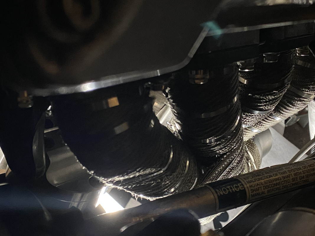
You May have to move engine over at bit so the steering shaft has some clearance with the header.
Steering shaft clearance Adjusting engine position Using 2x4 for adjusting C-beam
Bolt the headers on but don�t tighten the mounts until the rest of the drivetrain is in.
You May have to move engine over at bit so the steering shaft has some clearance with the header.
Steering shaft clearance Adjusting engine position Using 2x4 for adjusting C-beam
bill gave me the c beam measurements at the driveshaft to tunnel . I�ll leave everything loose at the mounts until I get the zf back in and then move it over. My clearance was extremely slight maybe 1/16 at the primary to steering shaft.. and turning right I had a very slight vibration through the wheel from contact. But, I don�t feel that may have been the optimal position (or maybe it is). I did simple my primary for a bit of clearance , but the header wrap takes some of that back. Right now it�s moved over all the way to the passenger side as the clearance is quite a bit !
5abivt, how do you like the header wrap? I bet that helps keep the heat down in the engine compartment. Are your headers also ceramic coated like jet hot?
5abivt, how do you like the header wrap? I bet that helps keep the heat down in the engine compartment. Are your headers also ceramic coated like jet hot?
Header wrap is one of those things I wish I would have done when I had the chance....
5abivt, how do you like the header wrap? I bet that helps keep the heat down in the engine compartment. Are your headers also ceramic coated like jet hot?
mine reason I did it was aesthetics.. to match my floor tunnel.. but yes with the new cooling system , goal was to try and reduce the underhood temps. I was polishing them first .. but couldn�t keep my mind off the benefits of reduced heat especially since they aren�t visible on the Z . So I had them coated Cerakote turbine coat, with a cobalt ceramic top coat. The idea was to try and reduce temps as much as possible and still try and protect the steel from the wrap containing the heat as well. It�s my belief the wrap is far more effective than a coating but it has a life span as well so we�ll see how that works out! I�ll update with pics in my build thread .. lot to catch up on there !
Regarding ceramic coating or wrapping to reduce heat, I've had my SW (stainless) headers installed for over 10 years and 30k miles including several cross-country trips and NEVER found a moment of concern or discomfort because of the heat. What heat?
Designer Imagines A Corvette That Looks More Like a Corvette Than the Corvette
Slideshow: A Jaguar designer's personal project imagines what a modern front-engined Corvette might look like if Chevrolet revisited the golden age of the Stingray.