


LS1 to LS2 Conversion Harnesses
Thread Starter
Supporting Vendor


Joined: Dec 2001
Posts: 1,573
Likes: 31
From: A dealer near you.
LS1 to LS2 Conversion Harnesses
Please see our new cam sensor adapter harness

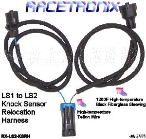
and our knock sensor relocation harness
Thank you.
Please see our new cam sensor adapter harness
and our knock sensor relocation harness
Thank you.
Last edited by Racetronix; Aug 2, 2005 at 08:14 PM.
Burning Brakes

Joined: Feb 2002
Posts: 1,137
Likes: 2
From: Texas
Racetronix,
I went to your site to buy these but when I clicked on the link that allows you to buy both of them, the price comes up as $69.98. The individual prices are listed at 29.99 for the knock kit and 24.99 for the cam kit, for a total of 54.98. Where does the extra 15.00 come from? Shipping and handling as listed at $0.00. I did not think it was shipping since it shouldn't even be close to 15.00. Then I thought maybe it was Canadian dollars, but is says USD.
Edit: Okay I went back to the web site and clicked on the option to buy each one individually and I see that the 15.00 is for shipping and handling. If you buy them separately for whatever reason, you will get the 15.00 charge for S&H twice. I could not see the shipping and handling charge listed on the page where you order both (cam and knock) together because the description of what you are ordering is cut off and the shipping and handling note is there and not where it actually says shipping. I just shipped a relatively heavy ATI F1R head unit from Texas to New Jersey for $20 with $3000 in insurance. Why is the shipping so costly? Is this overnight?
--Sean
Last edited by R6_C5_CLS55; Jul 30, 2005 at 10:35 AM.

Le Mans Master


Joined: Sep 2000
Posts: 6,976
Likes: 527
From: Clouds Over California
Originally Posted by Z06Convert
Yeah, it might be a simple task for some, but don't put down a vendor for trying to offer a simple solution to something that might not seem so easy for some people. 
I didn't think he was putting down the vendor until you mentioned it. It's nice for other's to be able to see that there is an economical solution for those more talented, or time to do it.
I already had some experience doing this when I helped Andy out on his motor going into his old C6. It really is no big deal.
But there is nothing wrong with somebody coming up with easy PNP parts. In contrast, just because somebody points out that they can do it for $3.00 does not mean they are bashing the vendor for producing something that does the same thing for $65.00. It's just FYI.
Thread Starter
Supporting Vendor
Joined: Dec 2001
Posts: 1,573
Likes: 31
From: A dealer near you.
Originally Posted by babala65
Nice idea, but I made both of my harness for under $3.00 
The material cost for our harnesses is above $3.00 esp for the knock sensor relocation harness. Silver / Teflon wire and FB loom is not cheap.
Thread Starter
Supporting Vendor
Joined: Dec 2001
Posts: 1,573
Likes: 31
From: A dealer near you.
Originally Posted by R6_C5_ML430
Racetronix,
I went to your site to buy these but when I clicked on the link that allows you to buy both of them, the price comes up as $69.98. The individual prices are listed at 29.99 for the knock kit and 24.99 for the cam kit, for a total of 54.98. Where does the extra 15.00 come from? Shipping and handling as listed at $0.00. I did not think it was shipping since it shouldn't even be close to 15.00. Then I thought maybe it was Canadian dollars, but is says USD.
Edit: Okay I went back to the web site and clicked on the option to buy each one individually and I see that the 15.00 is for shipping and handling. If you buy them separately for whatever reason, you will get the 15.00 charge for S&H twice. I could not see the shipping and handling charge listed on the page where you order both (cam and knock) together because the description of what you are ordering is cut off and the shipping and handling note is there and not where it actually says shipping. I just shipped a relatively heavy ATI F1R head unit from Texas to New Jersey for $20 with $3000 in insurance. Why is the shipping so costly? Is this overnight?
--Sean
I went to your site to buy these but when I clicked on the link that allows you to buy both of them, the price comes up as $69.98. The individual prices are listed at 29.99 for the knock kit and 24.99 for the cam kit, for a total of 54.98. Where does the extra 15.00 come from? Shipping and handling as listed at $0.00. I did not think it was shipping since it shouldn't even be close to 15.00. Then I thought maybe it was Canadian dollars, but is says USD.
Edit: Okay I went back to the web site and clicked on the option to buy each one individually and I see that the 15.00 is for shipping and handling. If you buy them separately for whatever reason, you will get the 15.00 charge for S&H twice. I could not see the shipping and handling charge listed on the page where you order both (cam and knock) together because the description of what you are ordering is cut off and the shipping and handling note is there and not where it actually says shipping. I just shipped a relatively heavy ATI F1R head unit from Texas to New Jersey for $20 with $3000 in insurance. Why is the shipping so costly? Is this overnight?
--Sean
Thunder Racing should have these in stock late this coming week. Shipping from their location in LA would be much cheaper if you can wait the extra few days.
Corvette Stories
The Best of Corvette for Corvette Enthusiasts

Every 2027 Corvette Engine Explained
Joe Kucinski
Designer Imagines A Corvette That Looks More Like a Corvette Than the Corvette
Verdad Gallardo
10 Ugly Corvettes That We Still Kinda Love
Joe Kucinski
Top 10 Most Expensive Corvettes Ever Sold on Bring A Trailer
Brett Foote
10 Things Every Corvette Owner Needs (2026 Edition)
Michael S. Palmer
8 Most "Only Corvette Owners Understand" Quirks and Problems
Pouria Savadkouei
10 Reasons the C6 Z06 is Still A Performance Benchmark After 20 Years
Joe Kucinski
How Much Horsepower Every Corvette Engine "LOST" in 1972
Joe Kucinski
Top 10 DOs and DON'Ts for Protecting Your Convertible Top!
Michael S. Palmer
Thread Starter
Supporting Vendor
Joined: Dec 2001
Posts: 1,573
Likes: 31
From: A dealer near you.
Originally Posted by Eric Hawkins
So you use the LS2 knock sensor or the LS1 knock sensor?
LS1 Sensor Description
This knock sensor (KS) system uses one or 2 broadband one-wire sensors. The sensor uses piezo-electric crystal technology that produces an AC voltage signal of varying amplitude and frequency based on the engine vibration, or noise, level. The amplitude and frequency are dependant upon the level of knock that the KS detects. The control module receives the KS signal through a signal circuit. The KS ground is supplied by the engine block through the sensor housing.
One way the control module monitors the system is by output of a bias voltage on the KS signal wire. The bias voltage creates a voltage drop that the control module monitors and uses to help diagnose KS faults. The KS noise signal rides along this bias voltage, and due to the constantly fluctuating frequency and amplitude of the signal, will always be outside of the bias voltage parameters.
Another way the control module monitors the system is by learning the average normal noise output from the KS. The control module learns a minimum noise level, or background noise, at idle from the KS and uses calibrated values for the rest of the RPM range. The control module uses the minimum noise level to calculate a noise channel. The control module uses this noise channel, and the KS signal that rides along the noise channel, in much the same way as the bias voltage type does. As engine speed and load change, the noise channel upper and lower parameters will change to accommodate the normal KS signal.
In order to determine which cylinders are knocking, the control module only uses KS signal information when each cylinder is near top dead center (TDC) of the firing stroke. If the control module has determined that knock is present, it will retard the ignition timing to attempt to eliminate the knock. The control module will always try to work back to a zero compensation level, or no spark retard. An abnormal KS signal will fall within the noise channel or will not be present. KS diagnostics are calibrated to detect faults with the KS circuitry inside the control module, the KS wiring, or the KS voltage output.
LS2 Sensor Description
This knock sensor (KS) system uses one or 2 flat response 2-wire sensors. The sensor uses piezo-electric crystal technology that produces an AC voltage signal of varying amplitude and frequency based on the engine vibration or noise level. The control module receives the KS signal through a signal circuit. The KS ground is supplied by the control module through a low reference circuit.
The control module learns a minimum noise level, or background noise, at idle from the KS and uses calibrated values for the rest of the RPM range. The control module uses the minimum noise level to calculate a noise channel. A normal KS signal will ride within the noise channel. As engine speed and load change, the noise channel upper and lower parameters will change to accommodate the normal KS signal, keeping the signal within the channel. In order to determine which cylinders are knocking, the control module only uses KS signal information when each cylinder is near top dead center (TDC) of the firing stroke. If knock is present, the signal will range outside of the noise channel.
If the control module has determined that knock is present, it will retard the ignition timing to attempt to eliminate the knock. The control module will always try to work back to a zero compensation level, or no spark retard. An abnormal KS signal will stay outside of the noise channel or will not be present. KS diagnostics are calibrated to detect faults with the KS circuitry inside the control module, the KS wiring, or the KS voltage output. Some diagnostics are also calibrated to detect constant noise from an outside influence such as a loose/damaged component or excessive engine mechanical noise.

Melting Slicks


Joined: Sep 2002
Posts: 3,064
Likes: 95
From: MI
Originally Posted by Racetronix
LS1 to LS2 Conversion Harnesses
Please see our new cam sensor adapter harness

and our knock sensor relocation harness

Thank you.
Please see our new cam sensor adapter harness
and our knock sensor relocation harness
Thank you.

Le Mans Master
Joined: Sep 2000
Posts: 6,976
Likes: 527
From: Clouds Over California
Originally Posted by Racetronix
LS1 sensor is used.
LS1 Sensor Description
This knock sensor (KS) system uses one or 2 broadband one-wire sensors. The sensor uses piezo-electric crystal technology that produces an AC voltage signal of varying amplitude and frequency based on the engine vibration, or noise, level. The amplitude and frequency are dependant upon the level of knock that the KS detects. The control module receives the KS signal through a signal circuit. The KS ground is supplied by the engine block through the sensor housing.
One way the control module monitors the system is by output of a bias voltage on the KS signal wire. The bias voltage creates a voltage drop that the control module monitors and uses to help diagnose KS faults. The KS noise signal rides along this bias voltage, and due to the constantly fluctuating frequency and amplitude of the signal, will always be outside of the bias voltage parameters.
Another way the control module monitors the system is by learning the average normal noise output from the KS. The control module learns a minimum noise level, or background noise, at idle from the KS and uses calibrated values for the rest of the RPM range. The control module uses the minimum noise level to calculate a noise channel. The control module uses this noise channel, and the KS signal that rides along the noise channel, in much the same way as the bias voltage type does. As engine speed and load change, the noise channel upper and lower parameters will change to accommodate the normal KS signal.
In order to determine which cylinders are knocking, the control module only uses KS signal information when each cylinder is near top dead center (TDC) of the firing stroke. If the control module has determined that knock is present, it will retard the ignition timing to attempt to eliminate the knock. The control module will always try to work back to a zero compensation level, or no spark retard. An abnormal KS signal will fall within the noise channel or will not be present. KS diagnostics are calibrated to detect faults with the KS circuitry inside the control module, the KS wiring, or the KS voltage output.
LS2 Sensor Description
This knock sensor (KS) system uses one or 2 flat response 2-wire sensors. The sensor uses piezo-electric crystal technology that produces an AC voltage signal of varying amplitude and frequency based on the engine vibration or noise level. The control module receives the KS signal through a signal circuit. The KS ground is supplied by the control module through a low reference circuit.
The control module learns a minimum noise level, or background noise, at idle from the KS and uses calibrated values for the rest of the RPM range. The control module uses the minimum noise level to calculate a noise channel. A normal KS signal will ride within the noise channel. As engine speed and load change, the noise channel upper and lower parameters will change to accommodate the normal KS signal, keeping the signal within the channel. In order to determine which cylinders are knocking, the control module only uses KS signal information when each cylinder is near top dead center (TDC) of the firing stroke. If knock is present, the signal will range outside of the noise channel.
If the control module has determined that knock is present, it will retard the ignition timing to attempt to eliminate the knock. The control module will always try to work back to a zero compensation level, or no spark retard. An abnormal KS signal will stay outside of the noise channel or will not be present. KS diagnostics are calibrated to detect faults with the KS circuitry inside the control module, the KS wiring, or the KS voltage output. Some diagnostics are also calibrated to detect constant noise from an outside influence such as a loose/damaged component or excessive engine mechanical noise.
Worthy description.

Pro


Joined: Sep 2002
Posts: 748
Likes: 0
From: NC
Please confirm that the cam sensor wire swap has been done in your harness. I believe the (2) outside wires (of the 3) need to get swapped to make the LS-2 work with LS-1 PCM.
Also do you have a LS2 90 MM TB harness kit for the C5's?
Brad
Also do you have a LS2 90 MM TB harness kit for the C5's?
Brad
Thread Starter
Supporting Vendor
Joined: Dec 2001
Posts: 1,573
Likes: 31
From: A dealer near you.
Originally Posted by bogielake
Please confirm that the cam sensor wire swap has been done in your harness. I believe the (2) outside wires (of the 3) need to get swapped to make the LS-2 work with LS-1 PCM.
Also do you have a LS2 90 MM TB harness kit for the C5's?
Brad
Also do you have a LS2 90 MM TB harness kit for the C5's?
Brad
We will have a FULLY PnP LS1 to LS2 TB adapter hopefully within 4-6 weeks. Prototypes are done.
We can provide the LS2 TB connector with flying leads in the interim.
Last edited by Racetronix; Aug 12, 2005 at 12:18 AM.
Platinum Supporting Vendor
Joined: Sep 2001
Posts: 5,730
Likes: 270
From: VENTURA Ca
I was ( I believe) the first to do the LS2 to LS1 conversion. I put the 427 in my C6 last year. I got the wiring schematics for both and figured out how to wire it. It was sort of a crap shoot. I had no idea if it would work or not, but I had to try it. I cut and spliced my own harnesses and made it work. It cost me almost nothing.
If you're contemplating swapping from LS2 to LS1 or vice versa, you are making a major investment. I have done a few of them and they work out great. The next one I do will have Racetronix harnesses on it. I'm not going to try to save $50 on a $10,000 job when that $50 will give me a clean, foolproof installation. Plug N Play is way better than Cut N Solder. Just my $.02
If you're contemplating swapping from LS2 to LS1 or vice versa, you are making a major investment. I have done a few of them and they work out great. The next one I do will have Racetronix harnesses on it. I'm not going to try to save $50 on a $10,000 job when that $50 will give me a clean, foolproof installation. Plug N Play is way better than Cut N Solder. Just my $.02
Racer

Joined: Dec 2003
Posts: 308
Likes: 0
From: Euless TX
Originally Posted by babala65
Nice idea, but I made both of my harness for under $3.00
hmmmm i spend 45k on a super car...
i think i can afford $60.00 for someone elses time to put together a nice out of the box solution.
pat yourself on the back for saving $57.00
Racer
Joined: Dec 2003
Posts: 308
Likes: 0
From: Euless TX
Originally Posted by Andy@AandACorvette
I was ( I believe) the first to do the LS2 to LS1 conversion. I put the 427 in my C6 last year. I got the wiring schematics for both and figured out how to wire it. It was sort of a crap shoot. I had no idea if it would work or not, but I had to try it. I cut and spliced my own harnesses and made it work. It cost me almost nothing.
If you're contemplating swapping from LS2 to LS1 or vice versa, you are making a major investment. I have done a few of them and they work out great. The next one I do will have Racetronix harnesses on it. I'm not going to try to save $50 on a $10,000 job when that $50 will give me a clean, foolproof installation. Plug N Play is way better than Cut N Solder. Just my $.02
If you're contemplating swapping from LS2 to LS1 or vice versa, you are making a major investment. I have done a few of them and they work out great. The next one I do will have Racetronix harnesses on it. I'm not going to try to save $50 on a $10,000 job when that $50 will give me a clean, foolproof installation. Plug N Play is way better than Cut N Solder. Just my $.02
Thread Starter
Supporting Vendor
Joined: Dec 2001
Posts: 1,573
Likes: 31
From: A dealer near you.
ttt
Racetronix
sales@racetronix.com
C4 Fuel Pump Systems, C5 Fuel Pump Systems, High Impedance Injectors > 60# F/M, 57# F/M, 50# F/M, 42#, 37#, 32#, 28#, 32#, 24#
Please check our web page for low impedance flow-matched injectors from Siemens and Delphi ranging from 55-95lb/hr.
Racetronix
sales@racetronix.com
C4 Fuel Pump Systems, C5 Fuel Pump Systems, High Impedance Injectors > 60# F/M, 57# F/M, 50# F/M, 42#, 37#, 32#, 28#, 32#, 24#
Please check our web page for low impedance flow-matched injectors from Siemens and Delphi ranging from 55-95lb/hr.