When you click on links to various merchants on this site and make a purchase, this can result in this site earning a commission. Affiliate programs and affiliations include, but are not limited to, the eBay Partner Network.
Looking for some help on venting. Have the old procharger twin intercooler setup and the directions are a bit muddy. If someone could give me the steps required that would be great.
Do you have all of the parts? It sounds like you're just adding another check valve between the PCV valve and intake and routing the fresh air vent on the passenger side valve cover to the air filter.
On boosted setups I prefer a vented and unrecirculated setup. If you absolutely feel like you need to recirculate it, I would look at a Mighty Mouse wild setup as a catch can.
Last edited by INSTIG8R; Aug 14, 2023 at 09:20 AM.
if the objective of the catch can is to filter out the contaminants and junk in the oil, it seems wise to just "vent" and not try and filter out
I'm going to a d1x and hear the wisdom. I have the holley valve covers, so I'm thinking of just running each vent tube to a cheap "puke tank" mounted down lower and away from AC vents
the lines will go to the puke tank which is just vented to atmosphere
NO recirculation of the junk coming out. Cap off the valley and throttle body and let the valve covers breath.
the drag cars use a fitting on the headers to create vacuum and pull that junk into the exhaust and a vacuum pump to keep crank case pressure out and improve ring sealing
takes about 10hp to drive the vacuum pump, but typically results in a 20+ hp increase and much cleaner engine. Seems like a similar setup would work on the street.
Why? even the best catch cans still recirculate back into the engine. The gunk being pulled out has no biz going back in and it's expensive.
I'd like to look more into a vacuum pump that does a much better job of evacuation cc pressure and improving ring seal to reduce contamination.
hard to do, but I'm not a fan of the catch can that recirculates. With the increase blow by on turbo and supercharged engines, you need plenty of ventilation and processing more crap out of the oil
Yes sir. Just a thought. I've been very happy with mine and the service I received from MM. I can definitely say that it works especially at the track. Mine is on a 383 cu.in. with an A&A kit.
We have can systems that run a PCV system and ones that do not; It is two totally different operational groups, for different applications.
Both of ours have the ability to control crankcase pressure, as the PCV unit is hybrid venting standard.
Many regular street use vehicles prefer a pcv system due to the fumes control and crankcase filtration it provides, separate from emissions improvement.
Removing the oil from the fumes return during normal pcv cycle means that you can have the power handling without the compromise of losing the function.
That is what our 'PCV' can is for. It is full time air oil separation and part time liquid handling during blowby surges.
If it is a competition vehicle, where the oil changes are more frequent, and the smell of crankcase fumes is a non-issue that is what our 'RACE' can is for. It is full time liquid handling for blowby.
I have run them back to back on my personal c7 without a change in peak output (ran 7's both ways).
thanks, no offense the MM catch cans are great, my point is that a vacuum pump improves the crankcase evacuation and ring sealing which a catch can doesn't do.
It results in an increase not a decrease in hp. Why not use an electric vacuum pump like for the power brakes on big cam cars? Might take a pretty big one but you could rig it to activate over 50% throttle or something to pull out the crankcase pressure (and gunk)
It's very popular on the race cars and seems like it would help on the street same way. Especially for the FI cars where blow by is much higher.
we did that 16 years ago, it is more expensive, more complicated, and less reliable
and loading the rings unnecessarily just reduces the engines life
and at the discharge of the pump, turns out you still need a catch can
we tried all the wrong ways so our customers don't have to, although many come to us after spending in the wrong direction previously
on a true street driver / dual use vehicle, you are at heavy load approximately 0% of the time, and in vacuum 100%, so planning the vent system around being wide open would be misjudging the application
a racecar is where the racecar stuff goes
we have a great 'race' system for use in concert with a mechanical vacuum pump, our sportsman car won last weekend with it
thanks!! very good points and very much appreciate the sage advice
you right that even the bad A$$ street car wouldn't work too well with the full race setup vaccum system and for sure it's not cheap and packaging a problem
interesting about loading the rings too much. Time to look at the catch cans again. My last one didn't work out so well and made a big oily mess!!
I do not recommend a catch can or any unnecessary additional plumbing or lines. It takes energy to move fluids through lines. All the volume added will reduce the reaction time of the PCV system when switching from vacuum to WOT conditions. The additional lines cause friction which will slow the fluids and require extra energy to move the fluids the correct velocity.
Instead simply follow the instructions that come with the procharger. They look well though out. Its very simple I will explain.
The PCV system has two sides. Idle/Cruise and WOT.
The Idle/Cruise side connects directly from crankcase to intake manifold through a pcv valve. The direction of FLOW is important to the pcv valve. The Procharger should come with its own pcv valve much higher quality and Chevrolet OEM. If it does not, you can use a Toyota SUpra 1998 twin turbo pcv valve, it is very high quality for boost applications.
I generally connect this side (idle/cruise) on the driver side valve cover from intake manifold on the brake booster line. The brake booster has a very large healthy line at the back of the manifold and you can put the pcv valve anywhere in that connection from valve cover to intake manifold suction as long as the direction of the pcv valve is correct, see my video below. It needs to stop boost from entering the crankcase. You must pressure test the intake system when you are done I will repeat this at the end.
The other side of the pcv system is the Wide open throttle side. That is the air filter to valve cover connection. Its just a vent to the air filter from the crankcase. There is NO pcv valve in this WOT side. It is simply a hose of the correct length and diameter (very short as possible length to minimize energy loss and around 3/8" diameter for a good trade of velocity and friction generally) to breath for the crankcase. At idle it sends air into the crankcase. At WOT it pulls air out of the crankcase. That is why there is no check valve or pcv valve in that line the flow will go both directions.
The filter is the critical component of WOT pcv. Your filter must be secure and have no leaking. You must pressure test the intake system from the filter area. Fill the plumbing into the compressor (supercharger head unit) with air from an air compressor to find all leaking. Here is a video showing how to do that and how the PCV valve should react and how the boost will stay inside the plumbing when you perform this test.
I just read the procharger instructions and I will elaborate on what they are doing. I do forced induction hundreds of PCV systems my own way so I normally will not read instructions but in order to interpret what they are doing for you I read it this time.
First line it says to cap off a breather. They probably mean the breather from pre-throttle body to valve cover #8 in the picture below 'pcv fresh air'. This is the old breather that used to feed from the air filter to valve cover. They want you to block it because now there will be boost in that throttle body hose. I would block it better than just a cap or zip tie or whatever. Use a bolt and a clamp like I did in my video. Notice in my video the beginning I had a bolt blow out and it was leaking boost from that line.
This fresh air to the valve cover is now provided by the air filter hole they want you to drill.
You don't need to drill a hole if you can attach the hose to the side of the pipe just after the air filter. If you get a pipe made of aluminum you can have a fitting welded to the side for the hose to number 8 back to the valve cover.
Next, I see they want you to remove the pcv valve and install a check valve with the pcv valve together. This is because factory pcv valve is garbage so the check valve helps it seal tightly together they work together. Notice in my video I did the same thing- I put the factory chevrolet check valve inline with the supra PCV valve (Check valve = pcv valve). However note that check valves are not pcv valves but pcv valves are check valves.
You can run the supplied check valve but honestly. I would upgrade to a supra pcv 1998 twin turbo pcv valve instead. Put that inline with the oem pcv valve so it faces the boost first, the first thing to see boost (closer to the intake manifold where the boost is). It may offer improved transition flow when moving from suction to boost conditions than a plain check valve which only has open or closed positions.
The C5 valve covers might be different than the one in the picture above. If they are the same, with the two hoses at the back feeding the pcv valve and the one hose up front feeding the air filter tube, then its fine. But if they are different you can get creative with it and do like I did with the one valve cover feeding the intake and the other valve cover feeding the filter.
the supra pcv sounds cool, designed for boost. Thanks for the info. The d1x is finally going on. The balancer was a bit of a challenge.
and the fancy accessory drive and blower belt bracket seem to be up to the task and much better than my old p1sc with the over stressed 6 rib
I'm confused about one thing "the wasted energy" Seems to me, any crank case pressure energy is already there from the blowby and "wasting the energy" is what you want to do to vent that pressure
also confused about the vacuum pump thing (not to be argumentative, trying to learn). Let's say we build a system that could flow enough to maintain a neg crankcase pressure even at full boost (albeit for the street)
I don't understand why that would put excess pressure on the rings?? that would add friction and reduce HP not add it. Clearly the vacuum systems on the drag cars running lots of revs and often with blowby (comes with the territory even on a well sealed engine) add a bit of hp.
Freaky example of blowby. Look in the top fuel pits. After a run, the oil comes out looking like well used nose goo instead of the fresh oil just put in before the run from all the nitromethane fuel washing by the rings.
I'm confused about one thing "the wasted energy" Seems to me, any crank case pressure energy is already there from the blowby and "wasting the energy" is what you want to do to vent that pressure
Friction causes pressure drop. For example if increase length of intake pipe that feeds the throttle body, it will create restriction as measured by map sensor and reduce mass flow (power) of the engine.
The engine is a vacuum pump. It pulls in air against friction. Longer tubes, more friction, less airflow can be moved.
An OEM wet sump pcv system utilizes some of the engine's vacuum pumping to run the PCV system, the energy comes from the engine pumping airflow that would normally pump outside air.
The ability of the engine to pump clear/clean its own crankcase depends on energy supplied to the PCV system against friction.
At idle and cruise there is sufficient energy and pressure drop to drive PCV through the tiny pcv valve, energy is not a concern because the engine is in a deep vacuum with energy to spare.
In other words an engine is capable of making say 400hp or 800hp or whatever, but it only needs 20hp to maintain an idle or cruise or something insignificant, so it has 100's of hp to spare worth of flow of which it only needs a couple hp to drive a OEM wet sump PCV system, the pressure drop is negligible.
At WOT everything changes. The intake is no longer in a state of deep depression vacuum. Now energy is in short supply. If the intake manifold is atmospheric pressure and the crankcase is higher than atmospheric pressure how can the engine produce a vacuum inside the crankcase to drive PCV?
PCV means a pressure below atmospheric at all times. NEVER above. PCV means always a vacuum in the crankcase.
The way the OEM of all engine manufacturers in the world handle this problem is by producing an air filter pressure drop and driving PCV near the deepest part of that pressure drop, usually in front of the throttle valve. This is a published paper from mechanical engineering scientist retrieved from google scholar.
The PCV system "thus utilizes the load-dependence of the pressure drop at the throttle valve"
We control the pressure drop via air filter and pipe length/diameter, whatever the air filter is attached to for example turbo/supercharger apps we measure it here in front of the compressor inlet which is attached to the crankcase.
I Show how to measure crankcase pressure at wide open throttle here in this video on forced induction application
If add lines and catch cans and all that extra equipment it will increase volume of crankcase and delay crankcase suction. Imagine trying to vacuum a tiny room vs a large room, it takes much longer to vacuum a larger room because there are more air molecules to move and remove.
If add lines and catch cans etc... it will add friction and the pressure of crankcase will rise closer to atmospheric possibly above atmospheric. It has negative impact on the energy supplied to the PCV system and a negative impact on crankcase pressure.
I'll answer the other questions in a different post
also confused about the vacuum pump thing (not to be argumentative, trying to learn). Let's say we build a system that could flow enough to maintain a neg crankcase pressure even at full boost (albeit for the street)
That is how OEM wet sump PCV systems work, and depending on the engines some have more vacuum than others. If you watch my video you will see I have a vacuum in my crankcase V8 turbo application even at 600rwhp full boost using OEM pcv setup.
As an example Nissan skyline uses a restrictor orifice, here is an OEM restrictor from Nissan Skyline
The restrictor allows the crankcase pressure to become much lower for idle/cruise. Low pressure is beneficial to the crankcase for many reasons, here are some off the top of my head
1. Reduced oil leaking
2. Scavenging blow-by gas out of engine oil (partial pressure of dissolved gas)
3. Reduced oil droplet radius and suspended volume
4. Improved piston ring seal and reduced blow-by
5. There is more but lets look at these
For 1. it should be obvious the higher the pressure is the more likely a leak can occur in gravity or otherwise. Oil seals always leak some molecules and the rate of leaking molecules is based on size of the molecule, surface area & phase/energy interactions, and scalar unit pressure.
This published paper briefly explains again about the intake suction, oil leaking, and oil/air separators influence on crankcase pressure I already covered some of in previous post
For 2 this is basic chemistry , pressure influence on dissolution of gas molecules, text book
e.g. lower pressure helps remove dangerous blow-by gas from engine oil, helps prevent deposits, wear, eventual failure of the engine.
For 3. There is an experiment we should turn attention to called oil droplet experiment, famous
drag force and droplet radius based on pressure (pressure prevents oil from returning to the oil pan and keeps oil droplets suspended and increases their diameter) Adjust pressure P (take the limit) and by inspection it is obvious what happens to droplet radius and drag force
For 4, improved ring seal and reduced blow-by we have much to discuss. But I have posted these details elsewhere so we can summarize and if you have questions I can search old detailed posts.
first look at this document from vacuum pump manufacturer, as it summarizes the good and bad of crankcase vacuum well IMO
now lets look at radial and axial forces on the piston ring to see what is happening
Gas pressure from above the ring is initially very high and notice it can get behind the ring to force the ring against the cylinder wall tightly. I think this is why detonation and high temperature can rip the top of the piston apart; the ring can compress so tightly the ring ends may butt and seize the ring in the bore, tearing the piston apart.
there is also some initial ring tension, static force tension to hold the ring to the cylinder wall in the absence of combustion pressure.
however, near the end of the power stroke, combustion pressure is reduced as the piston approaching bottom dead center, and the crankcase pressure (whatever the pressure is in the crankcase) Is going to force the piston ring up and try to un-seal the ring from the cylinder wall
The ring coming down has some inertia but friction with the cylinder wall and crankcase pressure is trying to pull it up and un-seal the ring. There are a number of problems associated with crankcase pressure which influence ring behavior, please see next published paper
Early ring switching, Axial flutter, Radial collapse, phenomena related to crankcase pressure at the end of power stroke which can be prevented by measuring and setting the crankcase pressure to a state of vacuum like the OEM engines from any manufacturer.
We are not re-inventing the pcv system here, we are merely discussing the consequences of going away from the original PCV system and how to bring back the OEM pcv system on a modified engine.
I don't understand why that would put excess pressure on the rings?? that would add friction and reduce HP not add it. Clearly the vacuum systems on the drag cars running lots of revs and often with blowby (comes with the territory even on a well sealed engine) add a bit of hp.
First, magnitude pressure scalar by inspection
Combustion pressure is often near in excess of 1000psi.
Crankcase pressure is in the range of -12 to 1psi.
the pressure on the rings during combustion is many magnitudes higher than the crankcase pressure. The rings will tolerate 1000psi of pressure or more. Even a powerful vacuum pump for dry sump system will produce merely in the range -12psi perhaps -14psi of vacuum or so, negligible to combustion. Many factory engines include dry sump systems which run moderate continuous crankcase depression such as Z06.
here we measure the Z06 crankcase pressure drop at idle
Modern engines often include crankcase pressure monitoring to throw a code "CEL" if there is a leak which causes pressure to rise in the crankcase.
This picture summarizes crankcase pressure targets with OEM PCV
The target for OEM Crankcase in wet sump applications for engines from the 1990 to 2010 is around 0.5" to 1.5" Hg (-0.25 to -0.75 PSI of vacuum)
The vacuum has increased over the years since then (2010~) in many OEM engine applications.
In performance applications we desire more vacuum just like modern engines in the crankcase to improve ring sealing and reduce blow-by contamination of engine oil, a target of 1.75" to 2.5" Hg is more ideal (-1.22~ PSI is 2.5" Hg)
Dry sump tend to run more vacuum than wet sump, and vacuum pumps supply the kinetic energy to run almost any vacuum for street setups. But vacuum pumps are not daily driver friendly, they require maintenance and increase the complexity of an engine for very little return or gain unless the engine is specifically built for high vacuum to take advantage.
Summary
Measure the crankcase pressure
Setup the PCV system as OEM
Adjust crankcase pressure as needed to hit target crankcase pressure for all operating conditions
I just read the procharger instructions and I will elaborate on what they are doing. I do forced induction hundreds of PCV systems my own way so I normally will not read instructions but in order to interpret what they are doing for you I read it this time.
First line it says to cap off a breather. They probably mean the breather from pre-throttle body to valve cover #8 in the picture below 'pcv fresh air'. This is the old breather that used to feed from the air filter to valve cover. They want you to block it because now there will be boost in that throttle body hose. I would block it better than just a cap or zip tie or whatever. Use a bolt and a clamp like I did in my video. Notice in my video the beginning I had a bolt blow out and it was leaking boost from that line.
This fresh air to the valve cover is now provided by the air filter hole they want you to drill.
You don't need to drill a hole if you can attach the hose to the side of the pipe just after the air filter. If you get a pipe made of aluminum you can have a fitting welded to the side for the hose to number 8 back to the valve cover.
Next, I see they want you to remove the pcv valve and install a check valve with the pcv valve together. This is because factory pcv valve is garbage so the check valve helps it seal tightly together they work together. Notice in my video I did the same thing- I put the factory chevrolet check valve inline with the supra PCV valve (Check valve = pcv valve). However note that check valves are not pcv valves but pcv valves are check valves.
You can run the supplied check valve but honestly. I would upgrade to a supra pcv 1998 twin turbo pcv valve instead. Put that inline with the oem pcv valve so it faces the boost first, the first thing to see boost (closer to the intake manifold where the boost is). It may offer improved transition flow when moving from suction to boost conditions than a plain check valve which only has open or closed positions.
The C5 valve covers might be different than the one in the picture above. If they are the same, with the two hoses at the back feeding the pcv valve and the one hose up front feeding the air filter tube, then its fine. But if they are different you can get creative with it and do like I did with the one valve cover feeding the intake and the other valve cover feeding the filter.
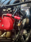
Could someone please tell me what that the hose for number 7 is in this pic? My snapped. I smell gas on that side of the engine now so I have to believe it's has something to do with that. Engine runs fine but I won't drive it like this.