
Seat Heater Installation completed. [pics and info]
 12-11-2008, 10:53 AM
#1
Melting Slicks

Thread Starter
Member Since: Feb 2004
Location: ATL
Posts: 3,195
Likes: 0
Received 2 Likes
on
2 Posts
St. Jude Donor '05-'06-'07-'08-'09-'10

I recently bought a set of seat heaters from a vendor (Redshift) from Parts For Your Car (PFYC.com) on CF.
For me the process broke down into three main categories -
1) Switch Installation.
2) Heater Pad Installation.
3) Wire Harness Installation.
The whole installation was done over two days. I took my time with the Traction Control Panel. I ran errands in between projects on both days.
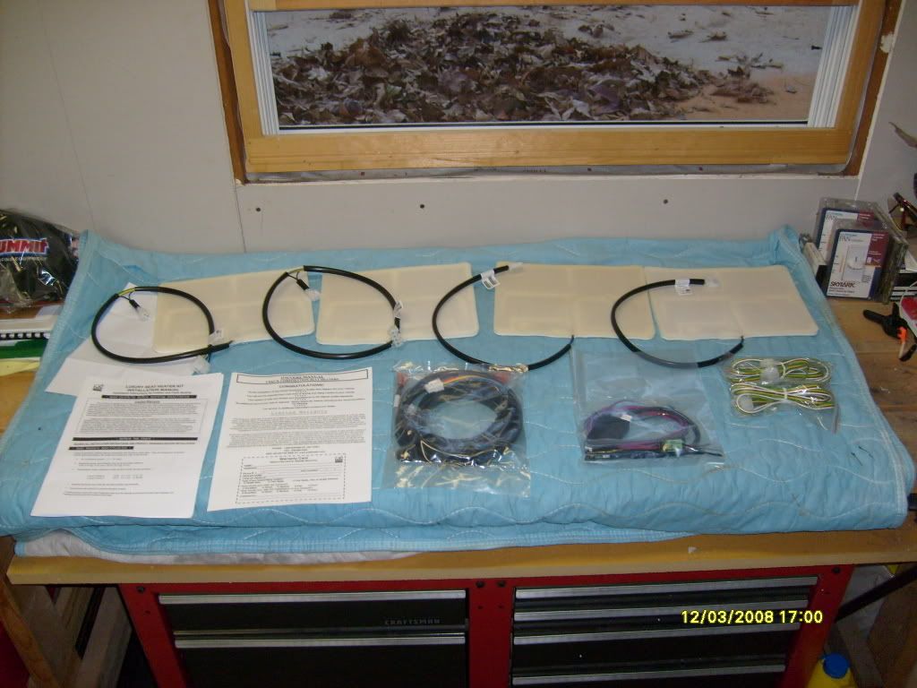
The package arrived last week. Shipping was very fast. Although it was my last day off work, I opened the box to check out the contents and what I was facing.
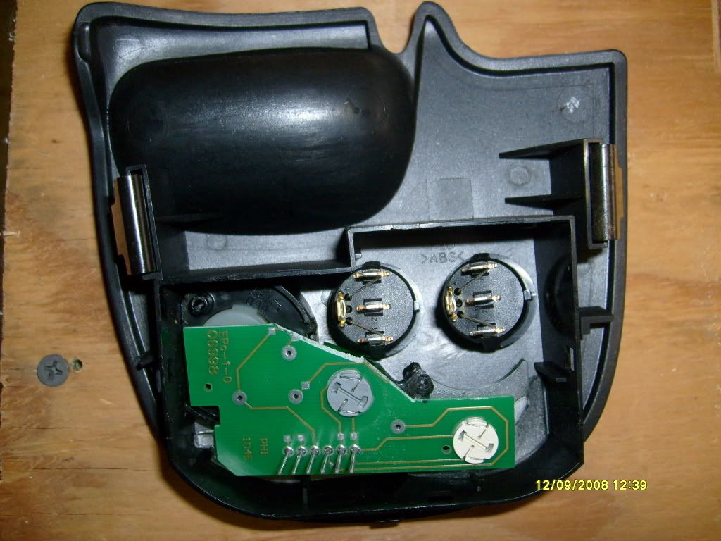
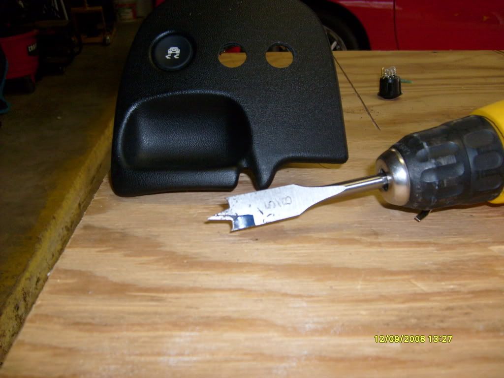
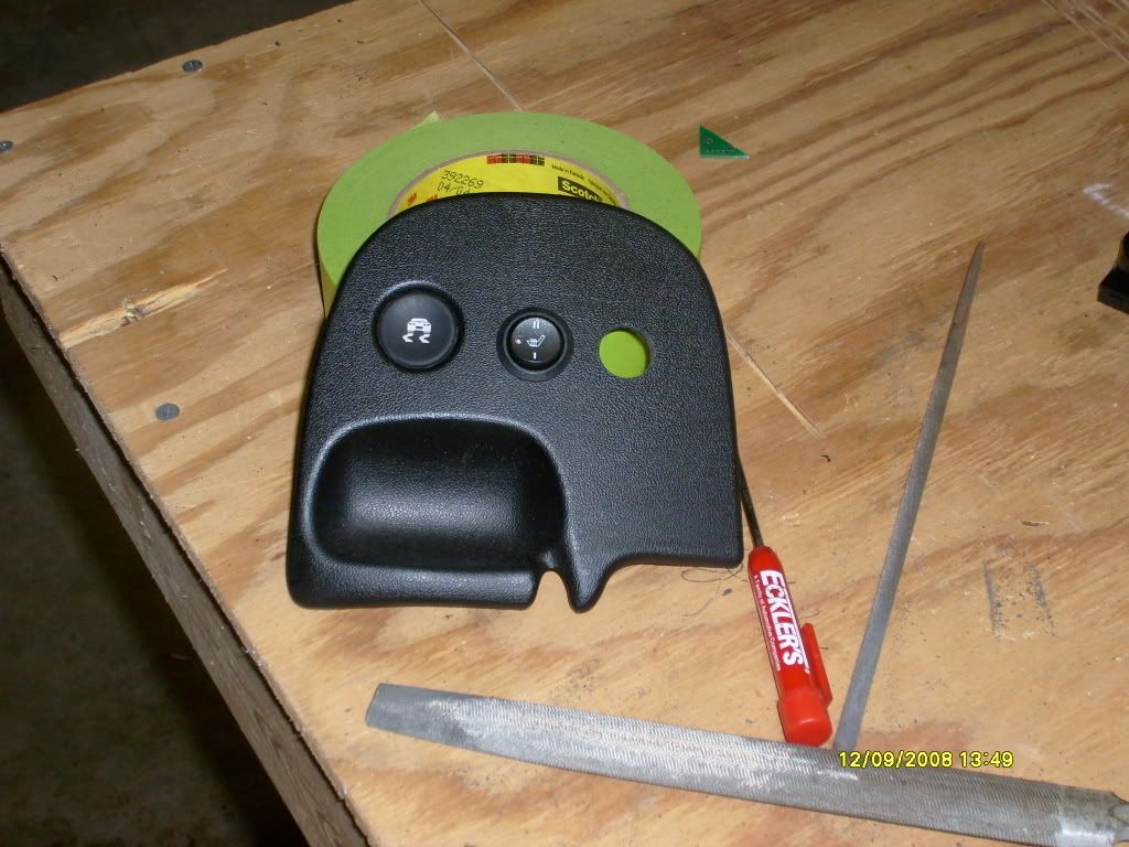
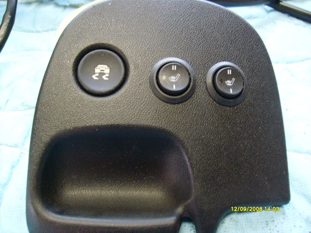
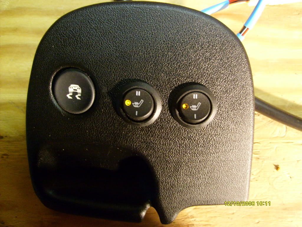
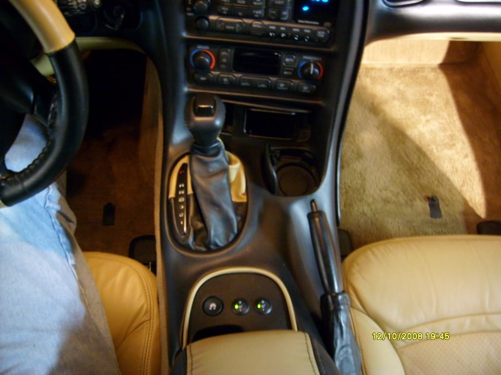
I started the project yesterday (Tuesday, 12-9-08). It took me a LONG time to commit to putting the switches where I wanted them in the first place. I just hated to cut up the circuit board and Traction Control Panel. I probably spent about two hours debating the whole thing. This is the only portion of the installation that is seen and I wanted to do as good of a job as possible.
Here you can see where I placed my switches temporarily from the back side and have already trimmed the circuit board.
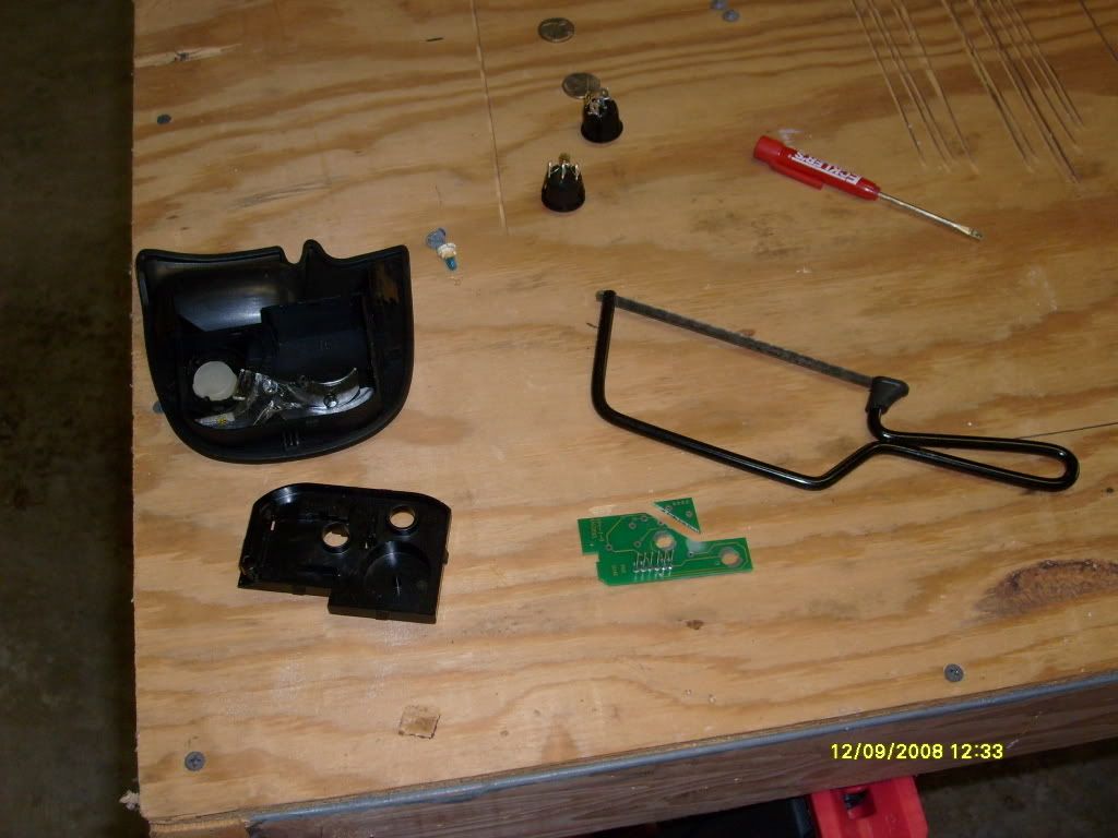
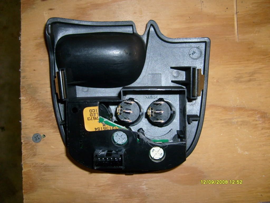
Here is the Traction Control Panel. I lined up my swtiches from the back side. I was concerned about clearance of the switches. I wanted to make sure I had enough room. I laid down a piece of tape on the back side of the panel and marked the first switch. I then drilled a pilot hole and then, from the front side, I drilled a 5/8 hole with a spade bit. I repeated the process for the second hole. It took a lot of filing but I wanted to make sure I had a good fit. There is a tab on the side of the switch that I had to notch out the panel for. It is an anti-rotational tab to keep the switch lined up.
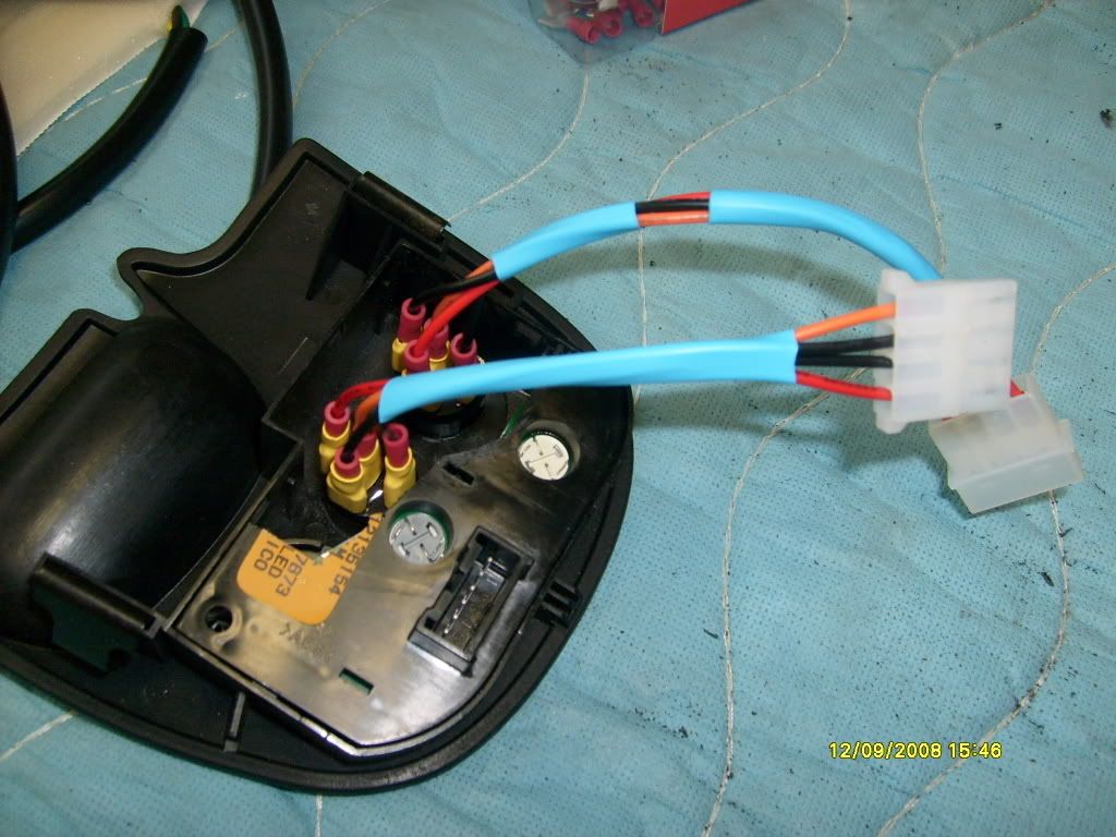
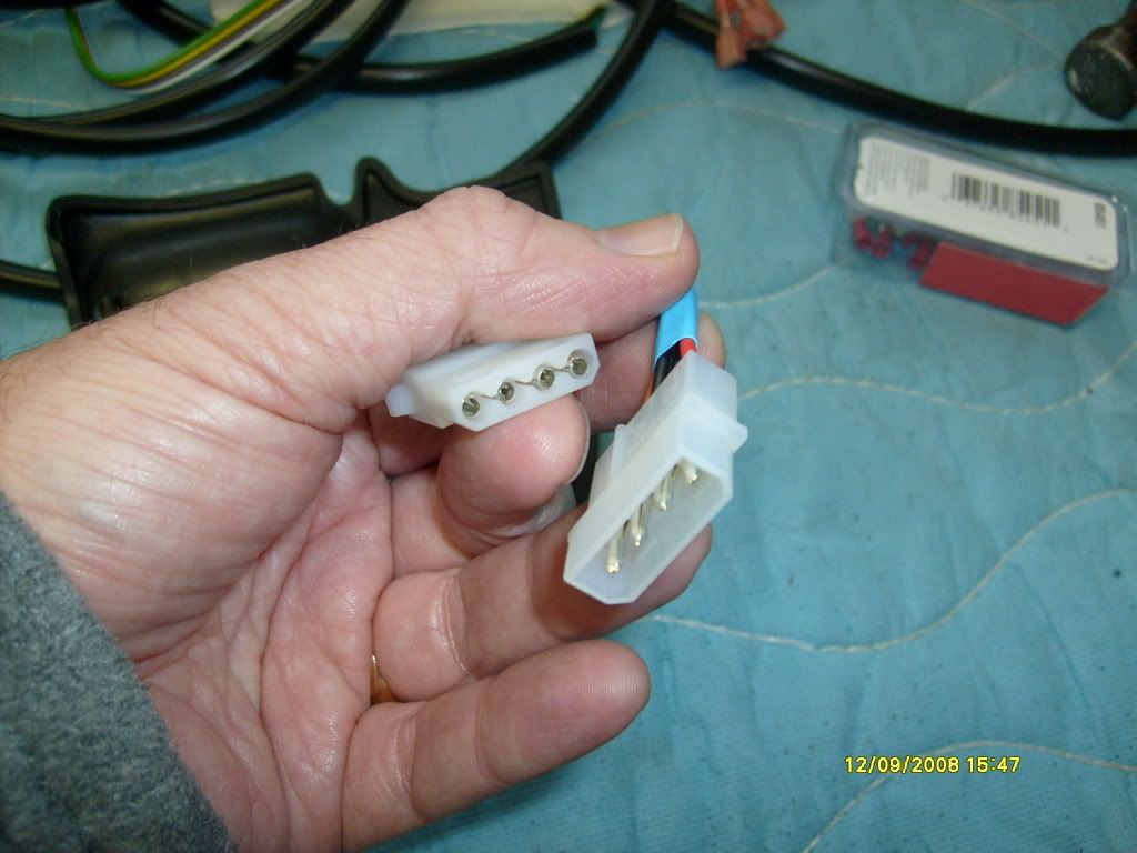
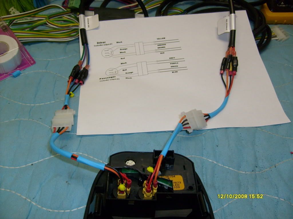
Because the switches are mounted in the Traction Control Panel, I did NOT want to have to undo eight connectors every time I had to take the panel out. More importantly, I did not want to have to reconnect eight connectors using a wire chart every time. I put together a harness to connect between the switches and the wire harness of the kit. I made the switch side have one female plug and the other a male plug. Hopefully this will "Murphy Proof" any future re connections.
Next up is the Heater Pad Installation.
For seat and skin removal I followed the instructions on the Vette Essentials web site. Thanks again fellas. Your information and documentation is great.
http://www.vetteessentials.com/instr...er_change.html
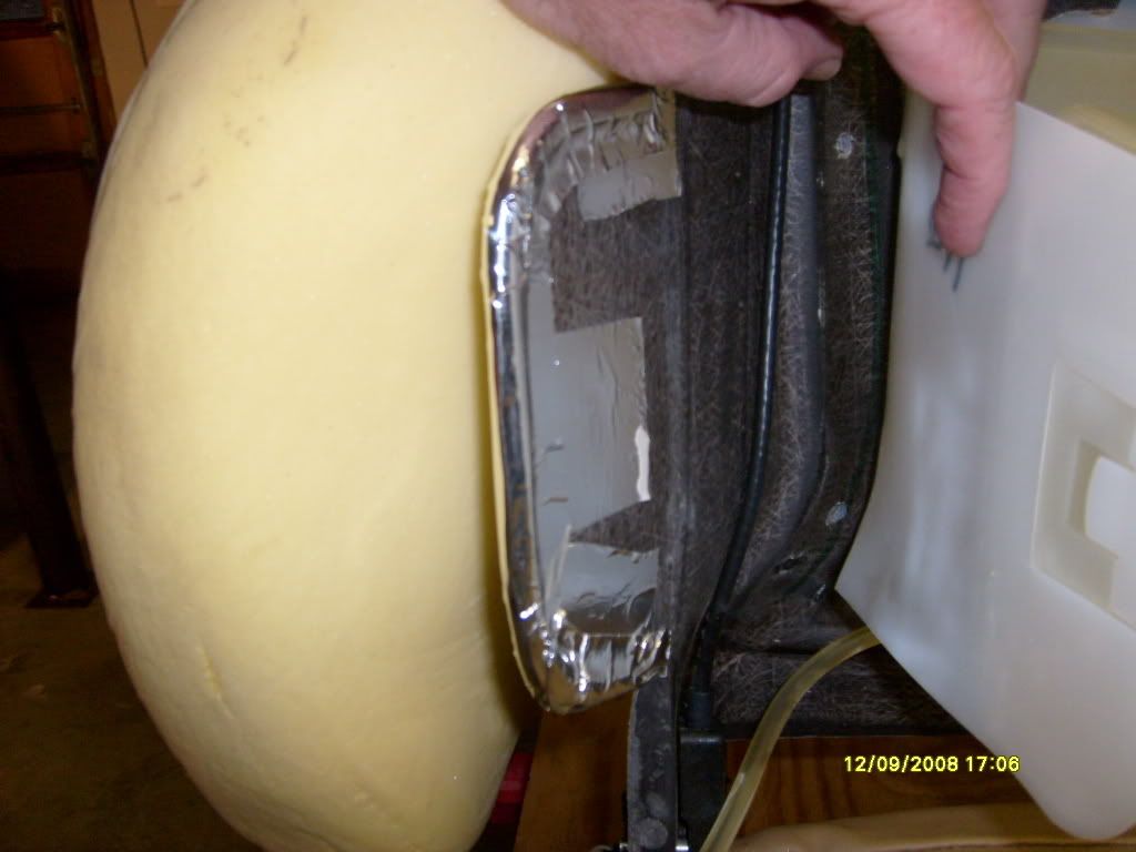
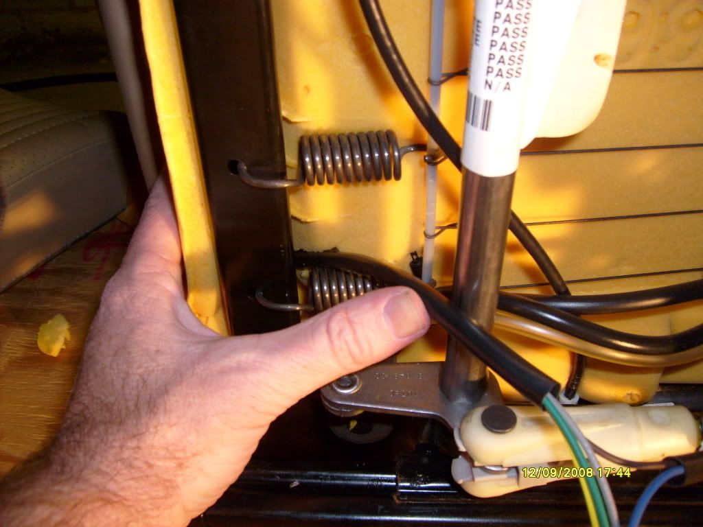
I added tubing to the outside bolster wings of both seats. Here is the passengers side.
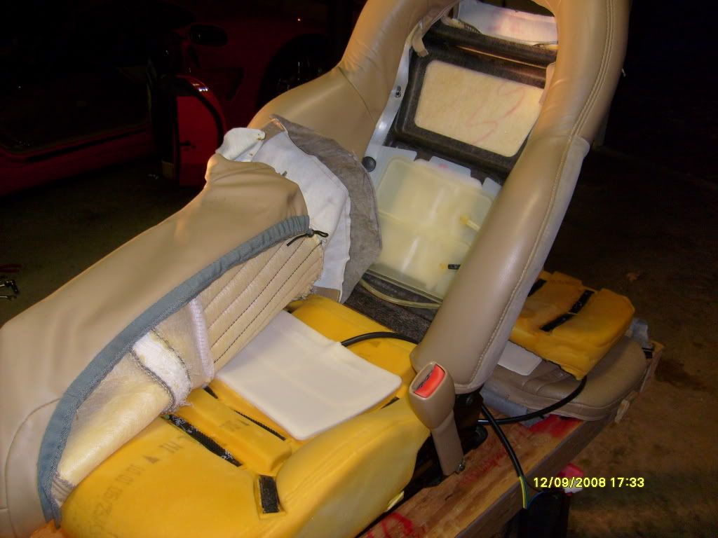
Here is the passengers side seat with the lower heating pad installed.
I ran the lower pad harness around the back side of the lower cushion.
I later secured the harness with tie wraps.
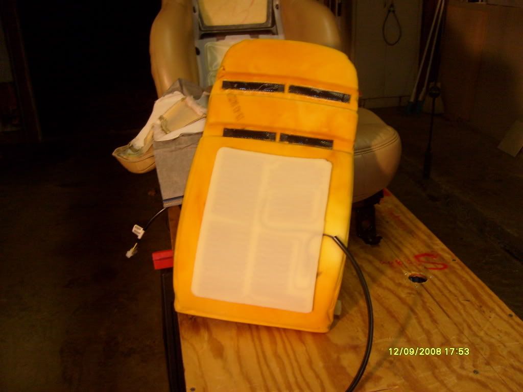
Here is the passengers side seat back with the heating pad installed. Once everything was back together, the back heating pad wire harness runs out the very back, lower portion of the leather seat skin. Make sure you leave enough slack in your connection to allow the seat to be angled all the way forward.

Here is another shot of my quick disconnect harness -
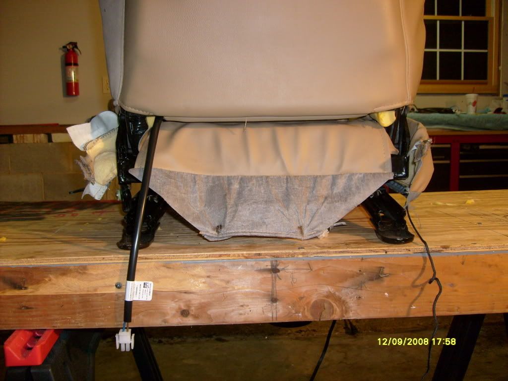
I started on the drivers side seat today, Wednesday, 12-10-08. I repeated the same process as with the passenger side seat. I ran the back heating pad harness down the inside of the seat. (the side where the seat belt attaches)
Once everything was installed, I hooked up the controller and wire harnesses and did a bench check of the system.
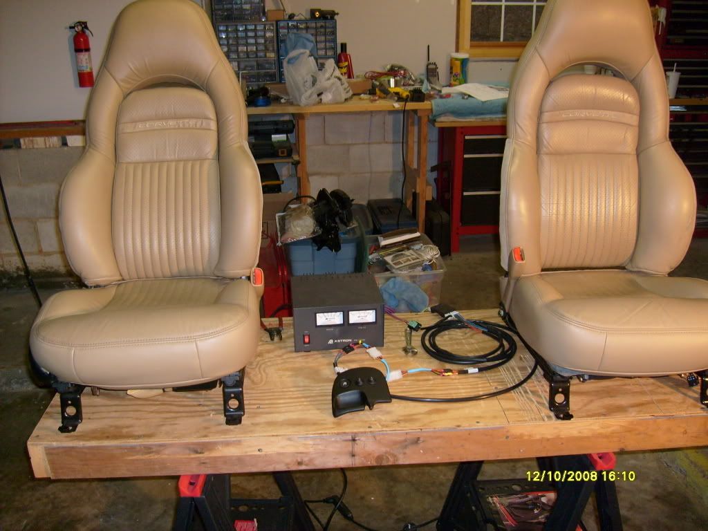
"HIGH" works great.
"LOW" works great too.
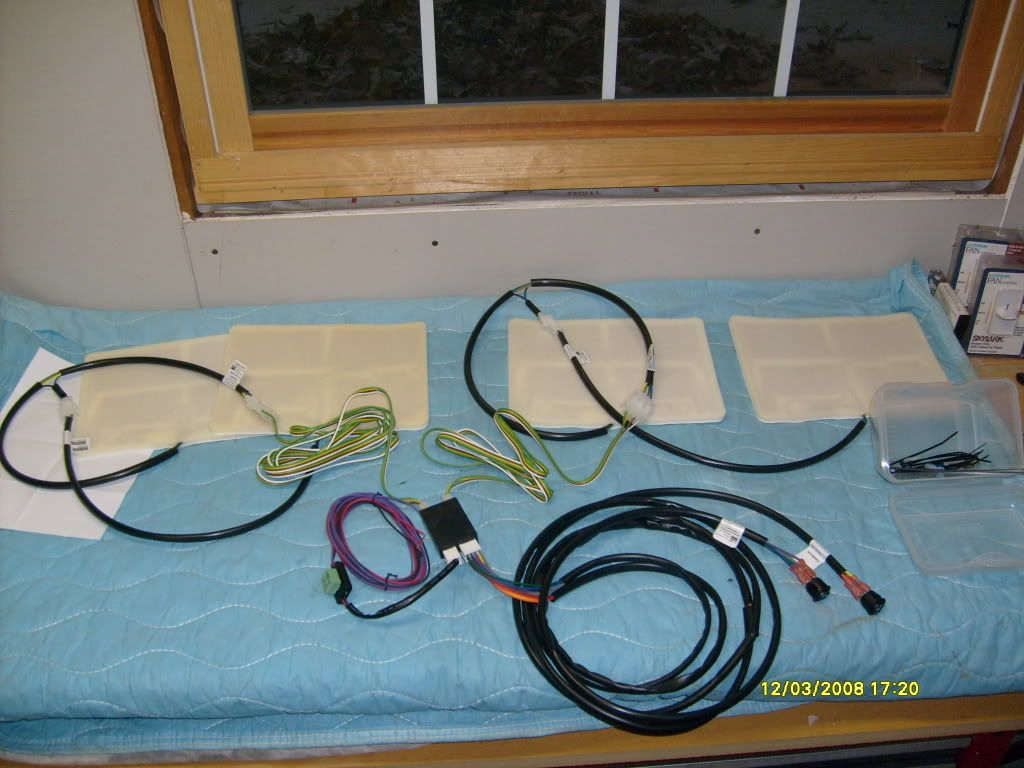
Next up - The wire harness installation.
This, IMO was a pain. I contacted the company that made the seat heaters. The person I spoke to said I could not cut the wires from the controller to the switches as that would void any warranty. There is not a lot of room inside the car for this kind of stuff. I have like nine feet of wire and need about three. I did the best I could with tie wrapping everything out of the way. I also left all the power and ground wires alone, uncut. I figured with all the other wires, it really would not make that big of a difference.
In no particular order -
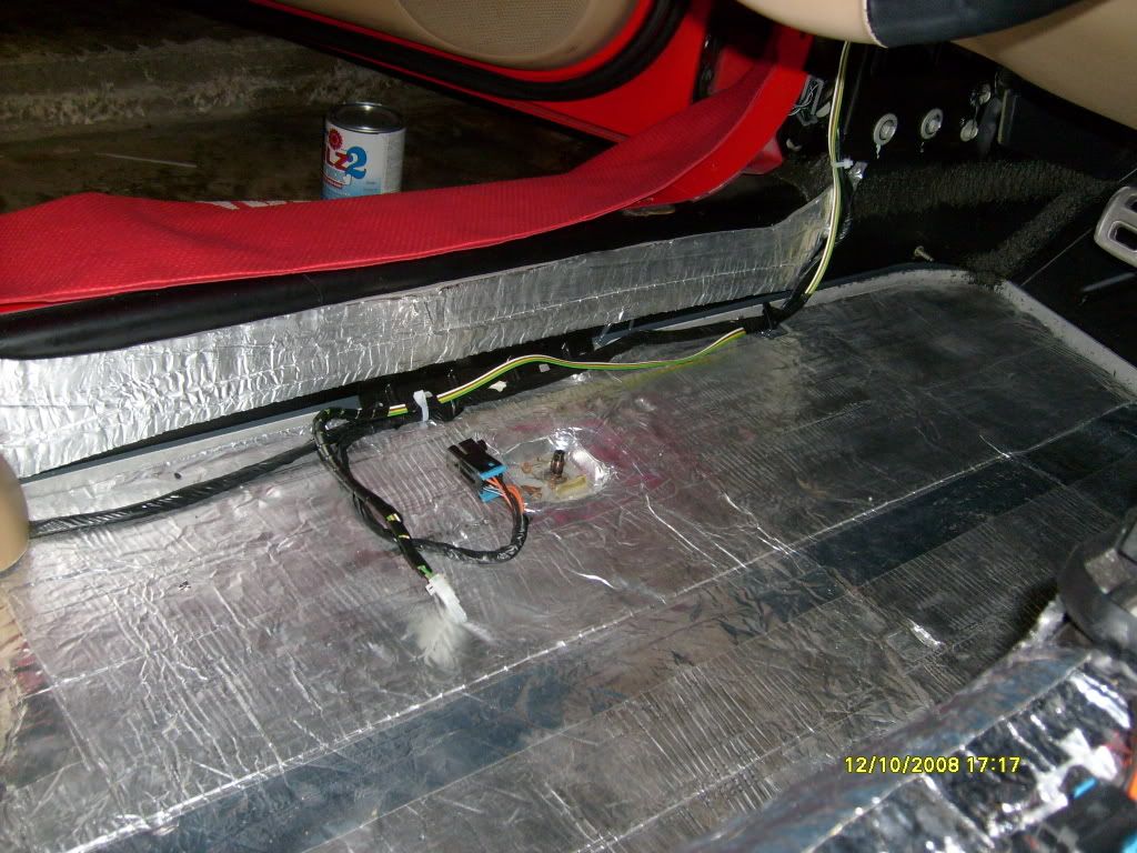
In the passenger foot well, upper left hand corner there is a bundle of three wires taped together.
The yellow wire is a switched circuit. I tapped into the yellow wire and put an in-line fuse.
The Power and Control wires are the red and purple wires tie wrapped just to the right of the blower motor.
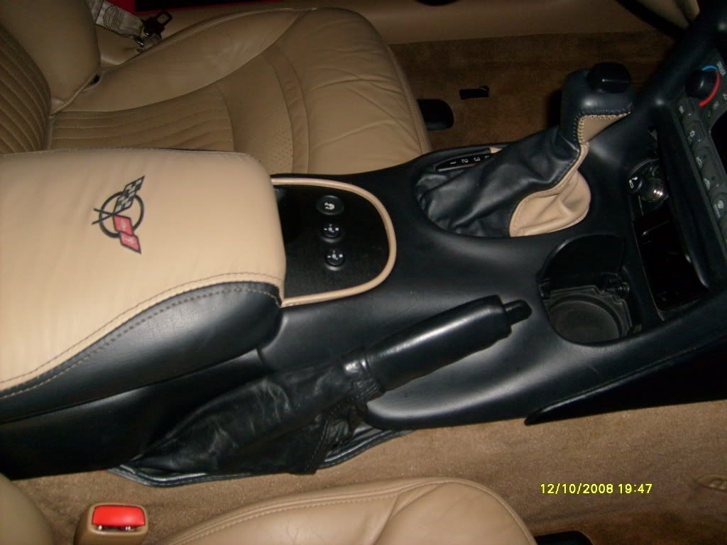
The big black bundle of wires are the harnesses (two) that run from the controller to the switches.
I ran the ground to the screw that is on the passengers side, near the tunnel, underneath that little bump-out of carpeting.
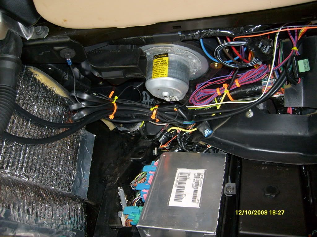
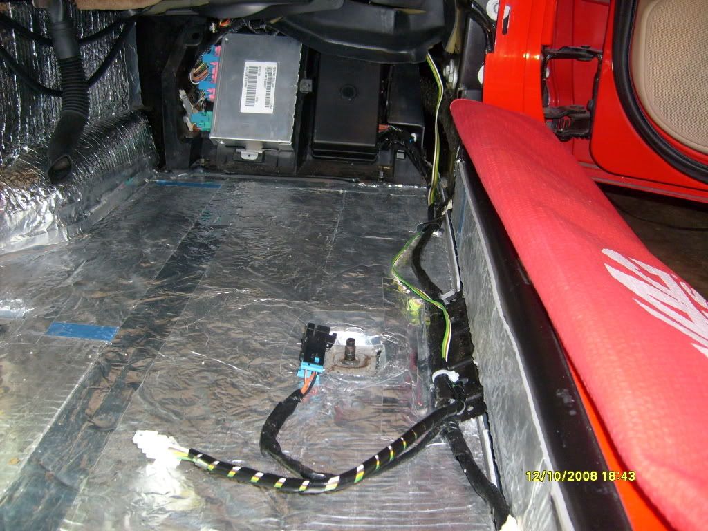
I fed the longer harness (9 feet) that runs from the controller to the seat above the tunnel and under the dash on the drivers side. I ran it down the outside with the seat control harness.
I secured the controller up high on the passengers side near the door side of the foot well.
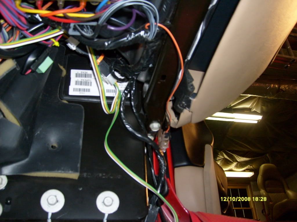
I ran the passengers side wire harness from the controller following the seat control harness.
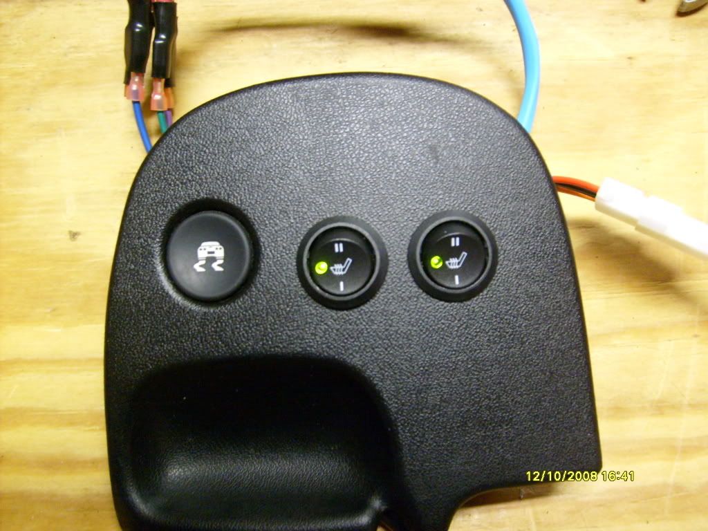
All back together and working great -
Here it is on "LOW".
Final shot -
VVVVVVVVVVVVVVVVV
For me the process broke down into three main categories -
1) Switch Installation.
2) Heater Pad Installation.
3) Wire Harness Installation.
The whole installation was done over two days. I took my time with the Traction Control Panel. I ran errands in between projects on both days.
The package arrived last week. Shipping was very fast. Although it was my last day off work, I opened the box to check out the contents and what I was facing.
I started the project yesterday (Tuesday, 12-9-08). It took me a LONG time to commit to putting the switches where I wanted them in the first place. I just hated to cut up the circuit board and Traction Control Panel. I probably spent about two hours debating the whole thing. This is the only portion of the installation that is seen and I wanted to do as good of a job as possible.
Here you can see where I placed my switches temporarily from the back side and have already trimmed the circuit board.
Here is the Traction Control Panel. I lined up my swtiches from the back side. I was concerned about clearance of the switches. I wanted to make sure I had enough room. I laid down a piece of tape on the back side of the panel and marked the first switch. I then drilled a pilot hole and then, from the front side, I drilled a 5/8 hole with a spade bit. I repeated the process for the second hole. It took a lot of filing but I wanted to make sure I had a good fit. There is a tab on the side of the switch that I had to notch out the panel for. It is an anti-rotational tab to keep the switch lined up.
Because the switches are mounted in the Traction Control Panel, I did NOT want to have to undo eight connectors every time I had to take the panel out. More importantly, I did not want to have to reconnect eight connectors using a wire chart every time. I put together a harness to connect between the switches and the wire harness of the kit. I made the switch side have one female plug and the other a male plug. Hopefully this will "Murphy Proof" any future re connections.
Next up is the Heater Pad Installation.
For seat and skin removal I followed the instructions on the Vette Essentials web site. Thanks again fellas. Your information and documentation is great.
http://www.vetteessentials.com/instr...er_change.html
I added tubing to the outside bolster wings of both seats. Here is the passengers side.
Here is the passengers side seat with the lower heating pad installed.
I ran the lower pad harness around the back side of the lower cushion.
I later secured the harness with tie wraps.
Here is the passengers side seat back with the heating pad installed. Once everything was back together, the back heating pad wire harness runs out the very back, lower portion of the leather seat skin. Make sure you leave enough slack in your connection to allow the seat to be angled all the way forward.
Here is another shot of my quick disconnect harness -
I started on the drivers side seat today, Wednesday, 12-10-08. I repeated the same process as with the passenger side seat. I ran the back heating pad harness down the inside of the seat. (the side where the seat belt attaches)
Once everything was installed, I hooked up the controller and wire harnesses and did a bench check of the system.
"HIGH" works great.
"LOW" works great too.
Next up - The wire harness installation.
This, IMO was a pain. I contacted the company that made the seat heaters. The person I spoke to said I could not cut the wires from the controller to the switches as that would void any warranty. There is not a lot of room inside the car for this kind of stuff. I have like nine feet of wire and need about three. I did the best I could with tie wrapping everything out of the way. I also left all the power and ground wires alone, uncut. I figured with all the other wires, it really would not make that big of a difference.
In no particular order -
In the passenger foot well, upper left hand corner there is a bundle of three wires taped together.
The yellow wire is a switched circuit. I tapped into the yellow wire and put an in-line fuse.
The Power and Control wires are the red and purple wires tie wrapped just to the right of the blower motor.
The big black bundle of wires are the harnesses (two) that run from the controller to the switches.
I ran the ground to the screw that is on the passengers side, near the tunnel, underneath that little bump-out of carpeting.
I fed the longer harness (9 feet) that runs from the controller to the seat above the tunnel and under the dash on the drivers side. I ran it down the outside with the seat control harness.
I secured the controller up high on the passengers side near the door side of the foot well.
I ran the passengers side wire harness from the controller following the seat control harness.
All back together and working great -
Here it is on "LOW".
Final shot -
VVVVVVVVVVVVVVVVV

 12-11-2008, 11:03 AM
#4
Platinum Supporting Vendor

Wow, what a fantastic write-up. Very detailed and helpful for people who want to attack this job. Your installation is no less than OEM quality. It looks great and I hope you enjoy the heat. I just had my motorcycle kit (from the same company) installed and plan to test it in the NC mountains this weekend on a cold extended ride.
Enjoy and thank you for choosing PFYC.
Enjoy and thank you for choosing PFYC.
__________________
Brian - ** I am no longer associated with PFYC.com **
Brian - ** I am no longer associated with PFYC.com **
12-11-2008, 11:06 AM
#5
Night Owl for life

Member Since: Nov 2003
Location: Bugs Bunny should'a made a left turn here
Posts: 23,219
Received 3,256 Likes
on
1,675 Posts

great writeup.
12-11-2008, 11:11 AM
#7
Melting Slicks
Thread Starter
Member Since: Feb 2004
Location: ATL
Posts: 3,195
Likes: 0
Received 2 Likes
on
2 Posts
St. Jude Donor '05-'06-'07-'08-'09-'10
Wow, what a fantastic write-up. Very detailed and helpful for people who want to attack this job. Your installation is no less than OEM quality. It looks great and I hope you enjoy the heat. I just had my motorcycle kit (from the same company) installed and plan to test it in the NC mountains this weekend on a cold extended ride.
Enjoy and thank you for choosing PFYC.
Enjoy and thank you for choosing PFYC.

Part of my install debate was where to run the wires out of the seat and how best to position the pads. I followed an example from a couple others here.
The wife's 300 has heated seats - first ones we have ever had. I'm sure we will enjoy these.
Have fun this weekend on the bike.
12-11-2008, 11:14 AM
#8
Platinum Supporting Vendor
Thank you for your kind words and for the hook-up with the heater kit.
Part of my install debate was where to run the wires out of the seat and how best to position the pads. I followed an example from a couple others here.
The wife's 300 has heated seats - first ones we have ever had. I'm sure we will enjoy these.
Have fun this weekend on the bike.
Part of my install debate was where to run the wires out of the seat and how best to position the pads. I followed an example from a couple others here.
The wife's 300 has heated seats - first ones we have ever had. I'm sure we will enjoy these.
Have fun this weekend on the bike.

Thanks, this weekend should be a blast. One last hurrah before my daughter is born in Feb.
12-11-2008, 04:24 PM
#9
Heel & Toe

Member Since: Mar 2006
Location: Tyrone GA
Posts: 15
Likes: 0
Received 0 Likes
on
0 Posts
I think you should of just moved to FLORIDA... Great job Jim..... it's suppose to get down to 30 here this weekend.. Maybe you can use them on your way over for the Christmas party............
12-11-2008, 04:41 PM
#10
Melting Slicks
Great install and write up. Looks factory! I don't drive mine enough in the cold weather to warrant that much work, but enjoy yours.
12-11-2008, 04:48 PM
#11
Race Director


Nice write up and images! I wouldn't mind doing this on my car except I don't really get to drive it in the winter months anyway. We sure like them in our Trailblazer and Silverado.
I cringed seeing that you had to cut the circuit board (warranty issue?)...seems like a nick or cut of the circuits could really ruin the project. But yours work ok?
I like where you mounted the switches on the console, very oem looking.
If I did this, I think I'd be more inclined to mount them in the oem ash tray and maybe the printed circuit board wouldn't have to be trimmed?
Nine feet of wire must allow for mounting of the switches in the doors, maybe?
You should add this to the sticky at the top of C5 Tech regarding DIY projects.
I wouldn't mind doing this on my car except I don't really get to drive it in the winter months anyway. We sure like them in our Trailblazer and Silverado.I cringed seeing that you had to cut the circuit board (warranty issue?)...seems like a nick or cut of the circuits could really ruin the project. But yours work ok?
I like where you mounted the switches on the console, very oem looking.
If I did this, I think I'd be more inclined to mount them in the oem ash tray and maybe the printed circuit board wouldn't have to be trimmed?
Nine feet of wire must allow for mounting of the switches in the doors, maybe?
You should add this to the sticky at the top of C5 Tech regarding DIY projects.
Last edited by hotwheels57; 12-11-2008 at 04:52 PM.
12-11-2008, 06:17 PM
#12
Melting Slicks


very nice work! your install looks very similar to mine, I bought the 3 setting kit from PFYC also, great customer service and support. like always I think I drove them crazy with questions before I bought my set. I had one small problem with mine that I found shortly after my install was done. PFYC offered great support and I had everything perfect a week later. nice job!
http://forums.corvetteforum.com/c5-g...t-heaters.html
http://forums.corvetteforum.com/c5-g...t-heaters.html
12-11-2008, 06:22 PM
#13
Platinum Supporting Vendor
very nice work! your install looks very similar to mine, I bought the 3 setting kit from PFYC also, great customer service and support. like always I think I drove them crazy with questions before I bought my set. I had one small problem with mine that I found shortly after my install was done. PFYC offered great support and I had everything perfect a week later. nice job!
http://forums.corvetteforum.com/c5-g...t-heaters.html
http://forums.corvetteforum.com/c5-g...t-heaters.html
I and Mike (the CEO) and all the people who work at PFYC are just like everyone else here. We are all true car enthusiasts. PFYC was started as a side business simply meant to supplement our gas money and turned into a company, but the premise then, as with now, is to provide high quality and unique items at great prices with awesome service.
Nothing has changed except we had to quit our day jobs...but we are still the same guys you will find hanging out at car shows, the track, autocross, races, and any other car event. By all means, we want everyone to be educated on his or her purchase to be sure s/he is happy with everything. Asking questions is part of that process.
Nothing makes us happier than when we see posts like this where people are thrilled at something that we helped them with. It's why we started PFYC in the first place. Now here we are 10 years later and loving every minute of it.
 12-11-2008, 06:44 PM
#16
Melting Slicks
Thread Starter
Member Since: Feb 2004
Location: ATL
Posts: 3,195
Likes: 0
Received 2 Likes
on
2 Posts
St. Jude Donor '05-'06-'07-'08-'09-'10
Nice write up and images! I wouldn't mind doing this on my car except I don't really get to drive it in the winter months anyway. We sure like them in our Trailblazer and Silverado.
I cringed seeing that you had to cut the circuit board (warranty issue?)...seems like a nick or cut of the circuits could really ruin the project. But yours work ok?
I like where you mounted the switches on the console, very oem looking.
If I did this, I think I'd be more inclined to mount them in the oem ash tray and maybe the printed circuit board wouldn't have to be trimmed?
Nine feet of wire must allow for mounting of the switches in the doors, maybe?
You should add this to the sticky at the top of C5 Tech regarding DIY projects.
I wouldn't mind doing this on my car except I don't really get to drive it in the winter months anyway. We sure like them in our Trailblazer and Silverado.I cringed seeing that you had to cut the circuit board (warranty issue?)...seems like a nick or cut of the circuits could really ruin the project. But yours work ok?
I like where you mounted the switches on the console, very oem looking.
If I did this, I think I'd be more inclined to mount them in the oem ash tray and maybe the printed circuit board wouldn't have to be trimmed?
Nine feet of wire must allow for mounting of the switches in the doors, maybe?
You should add this to the sticky at the top of C5 Tech regarding DIY projects.
The Traction Control switch and lighting still works fine. I was wondering if the additional circuity is for the Selective Ride ****, but I have no idea. I was worried about it not working, but after reading here and seeing that others have done the same thing with no effect, I was not too worried.
I have seen others mount the switches in the ash tray door itself, and also mount them to a panel and mount the panel over the ash tray (once removed).
I have also heard of them being mounted on the sides of the console. I will see one in person this weekend, but I'm liking where mine are at. I've seen several pictures of others here that have mounted them in the TCP and really like the way they did thiers.
I'm guessing at the Nine feet of wire between the controller and the switches, but its probably darn close. I'm sure they supply that much for all sorts of vehicle installations. I guess I could have mounted the controller in the back of the cabin and ran the switch harnesses instead.
Thanks again.
12-11-2008, 06:46 PM
#17
Platinum Supporting Vendor
 12-11-2008, 06:47 PM
#18
Instructor
Member Since: Jan 2007
Location: Fort Collins Colorado
Posts: 134
Likes: 0
Received 0 Likes
on
0 Posts
Nice job and report. I installed mine two years ago and absolutely love it. It is funny tho, when I was younger I thought who the heck needs heated seats. What a waste of money. Boy did I get that wrong!!!!
12-11-2008, 06:48 PM
#19
Melting Slicks
Thread Starter
Member Since: Feb 2004
Location: ATL
Posts: 3,195
Likes: 0
Received 2 Likes
on
2 Posts
St. Jude Donor '05-'06-'07-'08-'09-'10
very nice work! your install looks very similar to mine, I bought the 3 setting kit from PFYC also, great customer service and support. like always I think I drove them crazy with questions before I bought my set. I had one small problem with mine that I found shortly after my install was done. PFYC offered great support and I had everything perfect a week later. nice job!
http://forums.corvetteforum.com/c5-g...t-heaters.html
http://forums.corvetteforum.com/c5-g...t-heaters.html
Thank you.
I read your install thread several times, as well as others that I could find.

I had trouble actually starting to install the switches (cutting the board and drilling the holes).

I also had trouble finding a good way to run the harness wires from the heating pads. It all kind of fell in place once I got started.
Thanks for your kind words.