
Harmonic Balancer Bolt Torque


Safety Car

Joined: Dec 2004
Posts: 3,526
Likes: 20
From: Santa Fe TX
If it's a factory bolt:
1) it better be a new one as they are torque to yeild
2) there is not torque setting, the procedure is different on a C5, involves torque to a setting (40 ?) the turn xx degrees (270?),
Someone else can chime in with the correct numbers.
If it's an aftermarket bolt then it should come with the torque settings.
Either way you can search on here for the correct procedure.


Race Director


Joined: Apr 2004
Posts: 16,135
Likes: 5
From: Newberry FL
Cruise-In VIII Veteran
St. Jude Donor '07
www.ls1howto.com
NOTE:If you purchased an underdrive pulley, now is the time to install it, otherwise, use your stock pulley. Either way, the instructions are the same for install.
Seat your pulley back onto the snout of the crankshaft as best you can by hand. If you purchased a longer crank bolt, start threading this in now and pull the pulley on about a 1/4 or 1/2 an inch and remove the longer bolt. Use your old stock crank pulley bolt to pull the pulley onto the crankshaft until the bolt seems to get impossible to turn. Grab your biggest torque wrench and attempt to torque that bolt down to 240lbft. I have always stopped at 200lbft on my installs and I've never had a problem, so if you can't hit 240 (which I never have), don't worry about it. Now, break the bolt free and remove it.
Take your NEW crank pulley bolt and thread it in all the way by hand. Torque this bolt to 37lbft. Now, we need to stretch the bolt into place. Get your breaker bar and pipe extension, and try to turn the bolt 140degrees past where it is at now, keeping in mind the engine will be trying to turn some and those are degrees you can't count. Again, I always seem to get about 90-100 degrees worth (estimating, knowing what 90 degrees looks like) and leave it as is so don't worry about going crazy here.
Found this under the cam and heads install section. This is how I did it too.
Micah
Team Owner


Joined: Sep 2001
Posts: 23,283
Likes: 906
From: Lake Elsinore, CA
I think this simple procedure is one of the most misunderstood and improperly applied here. Here is the procedure from the Service Manual:
4] Use the J 41665 in order to install the crankshaft balancer.
5] Install the used crankshaft balancer bolt. Tighten the used crankshaft balancer bolt to 330 N�m (240 lb ft).
6] Remove the used crankshaft balancer bolt.
Important
The nose of the crankshaft should be recessed 2.40-4.48 mm (0.094-0.176 in) into the balancer bore.
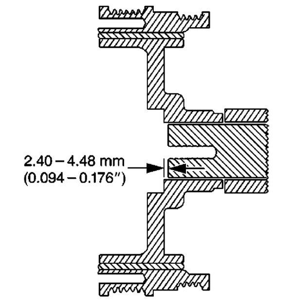
7] Measure for a correctly installer balancer. If the balancer is not installed to the proper dimensions, install the J 41665 and repeat the installation procedure.
8] Install the NEW crankshaft balancer bolt. Tighten
a. Tighten the new crankshaft balancer bolt a first pass to 50 N�m (37 lb ft).
b. Tighten the new crankshaft balancer bolt a second pass to 140 degrees using the J 36660-A.
The J 41665 is the GM balancer installation tool. There are several threads that instruct in the fabrication of a balancer installation tool using threaded rod, nuts and washers to substitue for the J 36660-A. I made one several years ago that worked great. Also it is a good idea to pin the pulley to the crank to prevent spinning problems in the future.
Here's a pic of a pinning tool.
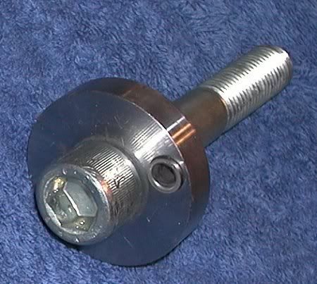
A pic of a pinned pulley - you can see the 1/4" dowel pin at 12 o'clock near the center.

A shot of my underdrive pulley. Note the two marks at 0 and 140 degrees I made to indicate when I had torqued the pulley sufficiently. The angle spec is to ensure the pulley has been pressed on the proper distance and that it will line up correctly with the belts.

4] Use the J 41665 in order to install the crankshaft balancer.
- Assemble the threaded rod, nut, washer and installer. Insert the smaller end of the installer into the front of the balancer.
- Use a wrench and hold the hex end of the threaded rod.
- Use a second wrench and rotate the installation tool nut clockwise until the balancer is started onto the crankshaft.
- Remove the tool and reverse the installation tool. Position the larger end of the installer against the front of the balancer.
- Use a wrench and hold the hex end of the threaded rod.
- Use a second wrench and rotate the installation tool nut clockwise until the balancer is installer onto the crankshaft.
- Remove the balancer installation tool.
5] Install the used crankshaft balancer bolt. Tighten the used crankshaft balancer bolt to 330 N�m (240 lb ft).
6] Remove the used crankshaft balancer bolt.
Important
The nose of the crankshaft should be recessed 2.40-4.48 mm (0.094-0.176 in) into the balancer bore.
7] Measure for a correctly installer balancer. If the balancer is not installed to the proper dimensions, install the J 41665 and repeat the installation procedure.
8] Install the NEW crankshaft balancer bolt. Tighten
a. Tighten the new crankshaft balancer bolt a first pass to 50 N�m (37 lb ft).
b. Tighten the new crankshaft balancer bolt a second pass to 140 degrees using the J 36660-A.
The J 41665 is the GM balancer installation tool. There are several threads that instruct in the fabrication of a balancer installation tool using threaded rod, nuts and washers to substitue for the J 36660-A. I made one several years ago that worked great. Also it is a good idea to pin the pulley to the crank to prevent spinning problems in the future.
Here's a pic of a pinning tool.
A pic of a pinned pulley - you can see the 1/4" dowel pin at 12 o'clock near the center.
A shot of my underdrive pulley. Note the two marks at 0 and 140 degrees I made to indicate when I had torqued the pulley sufficiently. The angle spec is to ensure the pulley has been pressed on the proper distance and that it will line up correctly with the belts.
Last edited by Patches; Jul 5, 2009 at 01:51 PM.
Race Director
Joined: Apr 2004
Posts: 16,135
Likes: 5
From: Newberry FL
Cruise-In VIII Veteran
St. Jude Donor '07
I think this simple procedure is one of the most misunderstood and improperly applied here. Here is the procedure from the Service Manual:
4] Use the J 41665 in order to install the crankshaft balancer.
5] Install the used crankshaft balancer bolt. Tighten the used crankshaft balancer bolt to 330 N�m (240 lb ft).
6] Remove the used crankshaft balancer bolt.
Important
The nose of the crankshaft should be recessed 2.40-4.48 mm (0.094-0.176 in) into the balancer bore.
7] Measure for a correctly installer balancer. If the balancer is not installed to the proper dimensions, install the J 41665 and repeat the installation procedure.
8] Install the NEW crankshaft balancer bolt. Tighten
a. Tighten the new crankshaft balancer bolt a first pass to 50 N�m (37 lb ft).
b. Tighten the new crankshaft balancer bolt a second pass to 140 degrees using the J 36660-A.
The J 41665 is the GM balancer installation tool. There are several threads that instruct in the fabrication of a balancer installation tool using threaded rod, nuts and washers to substitue for the J 36660-A. I made one several years ago that worked great. Also it is a good idea to pin the pulley to the crank to prevent spinning problems in the future.
Here's a pic of a pinning tool.
A pic if a pinned pulley - you can see the dowel pin at 12 o'clock near the center.
A shot of my underdrive pulley. Note the two marks at 0 and 140 degrees I made to indicate when I had torqued the pulley sufficiently. The angle spec is to ensure the pulley has been pressed on the proper distance and that it will line up correctly with the belts.
4] Use the J 41665 in order to install the crankshaft balancer.
- Assemble the threaded rod, nut, washer and installer. Insert the smaller end of the installer into the front of the balancer.
- Use a wrench and hold the hex end of the threaded rod.
- Use a second wrench and rotate the installation tool nut clockwise until the balancer is started onto the crankshaft.
- Remove the tool and reverse the installation tool. Position the larger end of the installer against the front of the balancer.
- Use a wrench and hold the hex end of the threaded rod.
- Use a second wrench and rotate the installation tool nut clockwise until the balancer is installer onto the crankshaft.
- Remove the balancer installation tool.
5] Install the used crankshaft balancer bolt. Tighten the used crankshaft balancer bolt to 330 N�m (240 lb ft).
6] Remove the used crankshaft balancer bolt.
Important
The nose of the crankshaft should be recessed 2.40-4.48 mm (0.094-0.176 in) into the balancer bore.
7] Measure for a correctly installer balancer. If the balancer is not installed to the proper dimensions, install the J 41665 and repeat the installation procedure.
8] Install the NEW crankshaft balancer bolt. Tighten
a. Tighten the new crankshaft balancer bolt a first pass to 50 N�m (37 lb ft).
b. Tighten the new crankshaft balancer bolt a second pass to 140 degrees using the J 36660-A.
The J 41665 is the GM balancer installation tool. There are several threads that instruct in the fabrication of a balancer installation tool using threaded rod, nuts and washers to substitue for the J 36660-A. I made one several years ago that worked great. Also it is a good idea to pin the pulley to the crank to prevent spinning problems in the future.
Here's a pic of a pinning tool.
A pic if a pinned pulley - you can see the dowel pin at 12 o'clock near the center.
A shot of my underdrive pulley. Note the two marks at 0 and 140 degrees I made to indicate when I had torqued the pulley sufficiently. The angle spec is to ensure the pulley has been pressed on the proper distance and that it will line up correctly with the belts.


