When you click on links to various merchants on this site and make a purchase, this can result in this site earning a commission. Affiliate programs and affiliations include, but are not limited to, the eBay Partner Network.
I'm Derek, and my brother has helped me so much and I can't thank him enough. We have a 3d printer and are replacing parts as they need be with the printer. This progress thread will be pic heavy. Sorry to all the low level scrubs on dialup. I live in the country and internet is not fast out here either.
I'm fairly new to the corvette world. I currently have my best friend's old 97 coupe. It was hydro-locked and totaled by insurance. I bought it from him for what he paid the insurance company (dirt cheap). I settled on replacing the ls1 with an ls6..... Because it fit right in. Not really, I have rewired it to match up with the factory pigtails. I no longer have the pics from the install but if this engine comes back out I'll take more and do a write up then. But for now here is the aftermath of what a tornado warning and trying to pick up your kid does to a ls1.
I do have my wiring harness documented and still have some to figure out. But yes it will work with the factory 97 bcm. Tc/abs work. The adjustable suspension f45 works ( well it's crap and will be replaced but it thinks it works)
I replaced the clutch with an ls7 unit and a tick master cylinder. I put a new gm TOB/ SLAVE CYLINDER in as well. .... It was bad. It did not have a stop and would over travel. So my first test drive was short and I came home to the bell housing leaking fluid. I thought well maybe I need a shim plate. Nope. It was just a bad slave cylinder. So I ordered and installed the 2nd new one with no shims and it works perfectly. I also installed a remote bleeder. If you ever have the driveline apart put in a remote bleeder. Just do it. Also the clutch, do to the over travel, managed to ratchet itself in so that it would not disengage. We watched some Audi videos ( they also have the self adjusting clutch) and were able to release it back to the factory spot. So that took care of the clutch problem.
I almost forgot, the fuel plumbing is different between the 97/98 and newer ls engines. The return is off the fuel rails for the older models, and the fuel filter/pressure regulator has a return built in it on the newer models. We bought a newer fuel filter and plumbed the return from into the existing lines. The replacement lines are way too expensive for what they are. I spliced one with a generic plastic GM/chrysler fuel line repair kit. I used a 90* quick connect for the fuel filter end and a straight quick connect on the other. I had zero luck with using a heat gun to splice the line together. I did get a great seal making a block to hold the hard line in a vice and used a socket to hammer the quick connect into the line.
So now on to some things I actually have the pics for.
Edit I guess I should show a pic or two of my car.
Last edited by Proletariat designs; Aug 19, 2017 at 09:42 PM.
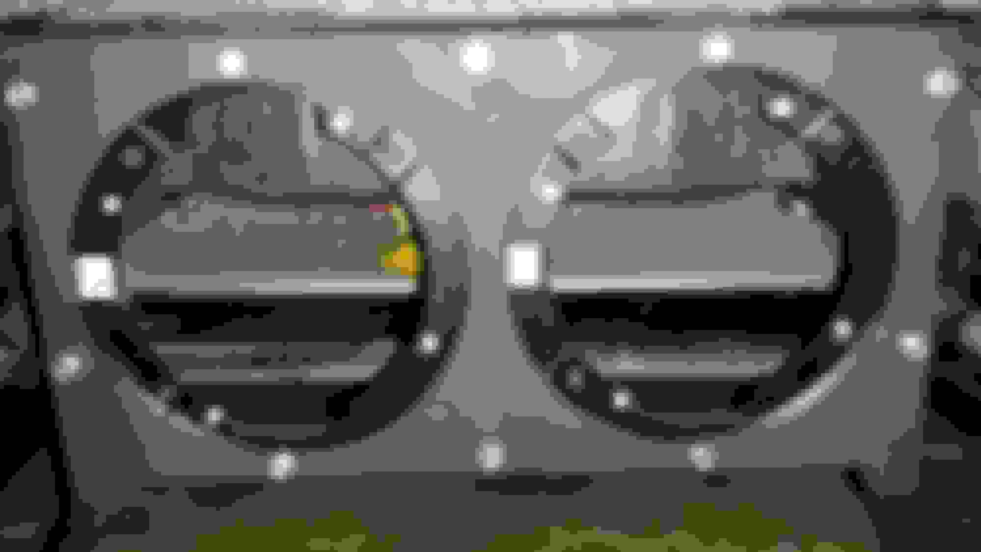
So the windshield wipers died. Checked the fuse in the passenger side foot well and it was good. So either the motor died or the switch on the column died. So let's figure it out.
First you'll have to pop the hood. If you need a photographer for that...... Stop and take the car to a mechanic lol. Seriously though you need to take a small flat head screwdriver or a small pick to pop the caps off the wiper arms.
Unhook the hoses for the cleaner. It will help to twist and pull so you don't break these 20 year old rubber hoses.
Now with a 13mm socket remove the nuts that hold on the wiper arms. Now you can rock the arms back and forth while pulling up to remove both arms.
Using the small screwdriver or pick, pop up the small fasters across the front of the cowl cover and remove them. Now you can slide the cowl cover down and flip it over and allow it to sit over the engine.
I completely removed the cover so I could use some back to black on it. All you need to do is push the rubber stoppers through and then allow the windshield wiper hoses to lay across the engine.
Use a t30 to loosen up the bolts that hold the motor to the transmission. Or take them completely out, the choice is yours.
Take out the three bolts that attach the transmission and remove the transmission from the car.
Unplug the motor and remove it.
And here's the problem. All that trash and debris clogging up the drain nipples. There are three. Just pull them up to remove. Clean them and then push them back in to reinstall.
Now for the good stuff. Use a multi meter to test the voltage on the green wire.
Off position should read as zero volts.
Intermediate low setting is around . It will increase as you increase the intermittent setting. The two continuous speeds are close to 12 volts.
If the pig tail is receiving voltage then the motor is bad. If you are receiving no voltage, it's a short in the wiring or the switch on the column is bad. I'd start with the column switch but you do you.
Use a t20 to remove the bracket from the motor and the rubber/plastic cover. Take it to the store for the core and get a new or remanufactured. Whatever fits the budget. Next pet the good boys and girls. This is the most important step.
Reinstalling is the reverse of the dismantle.
Before pics of wiper and cover before some paint and back to black. It worked pretty well. As you can see it had serious oxidation, and ended up looking decent.
I did mange to break one of the caps for the wiper arms. I will be printing a replacement for them and post a pic when I get that finished.
Last edited by Proletariat designs; Aug 19, 2017 at 07:19 PM.
My visor clip broke so I made a cad file and printed two off in tglase. It's a nylon based filament. It's tough enough to withstand the heat and abuse of firearms ( made several handguards with it)
so it should hold a visor from swinging around.
Last edited by Proletariat designs; Aug 19, 2017 at 08:34 PM.
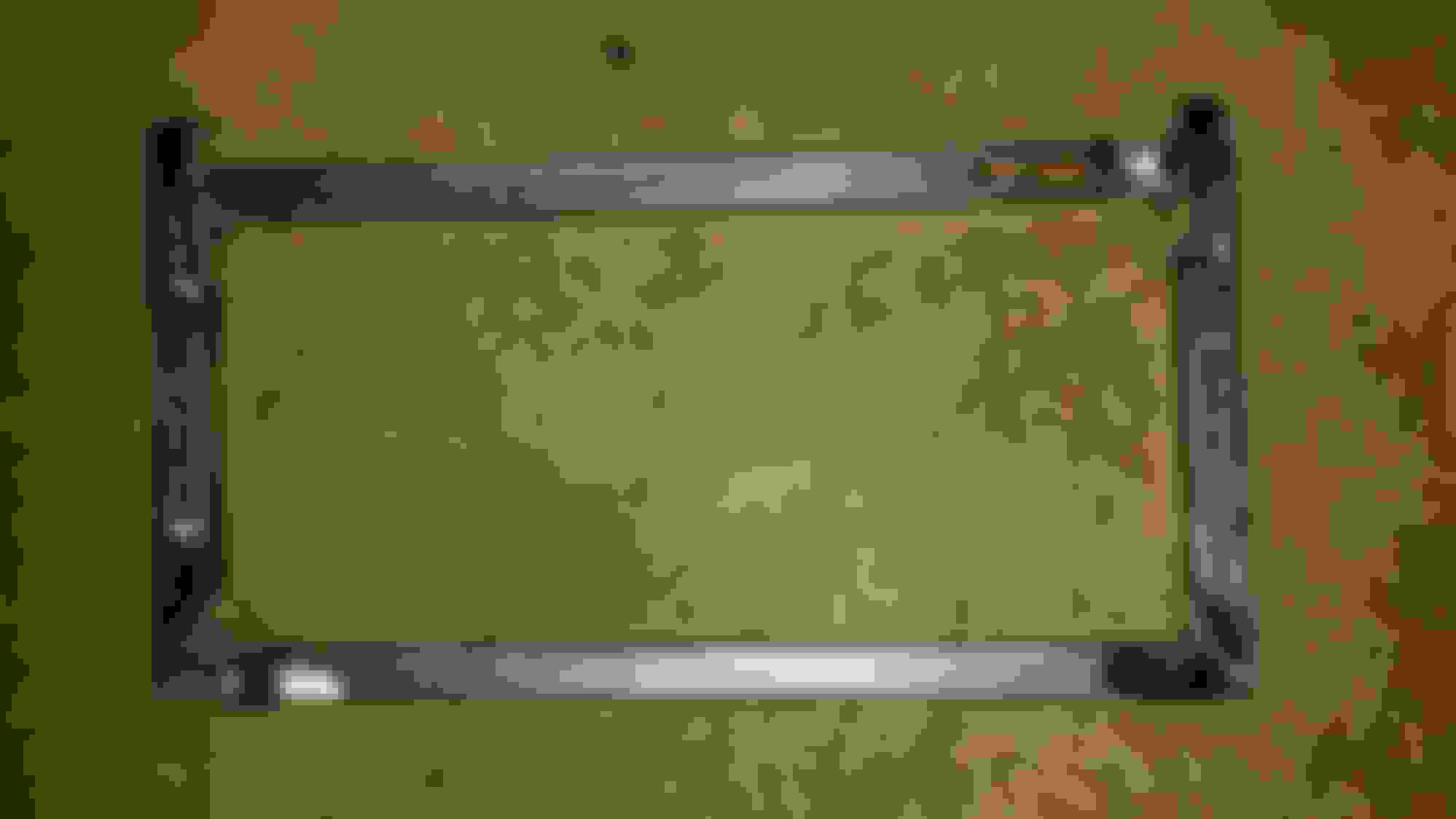
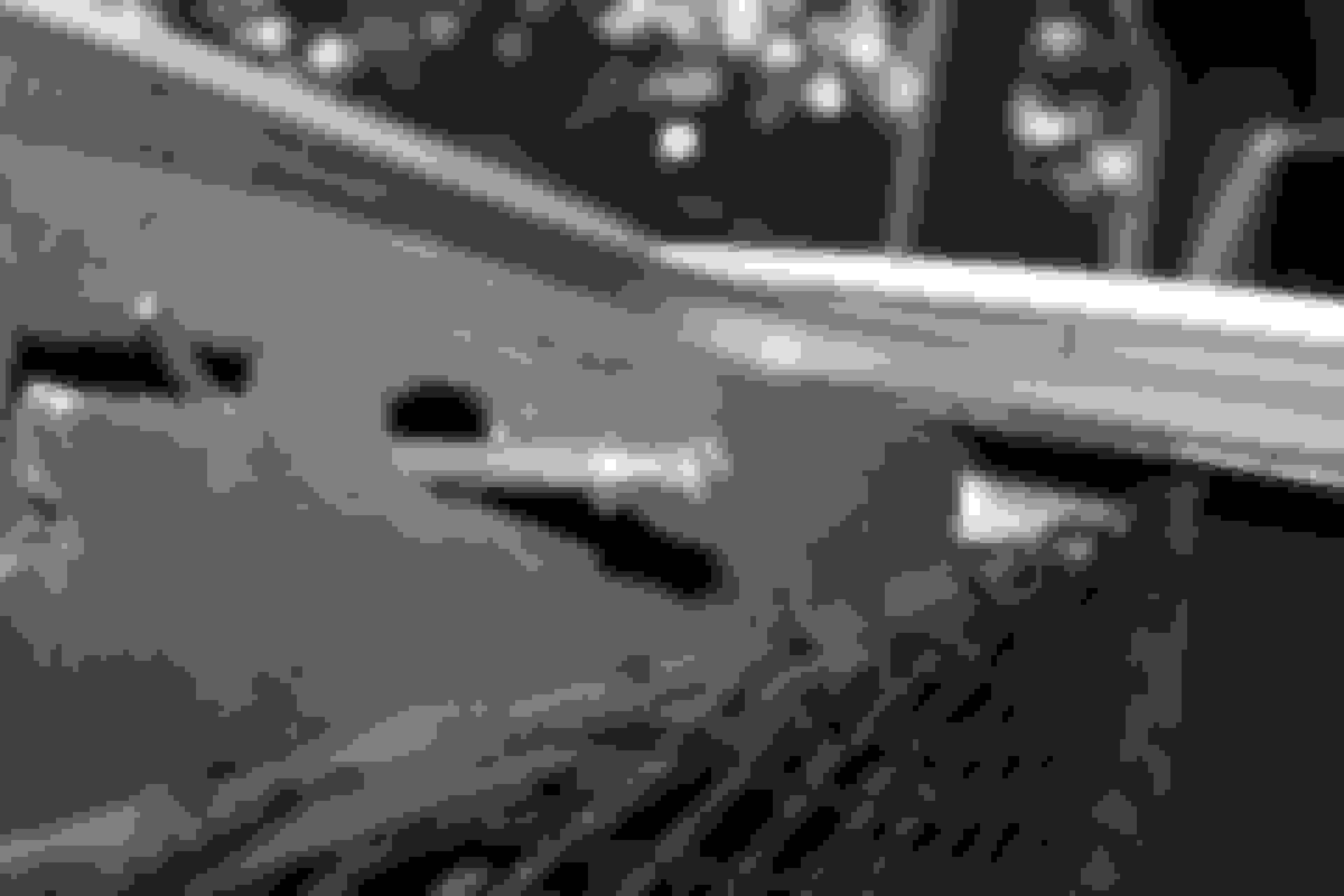
Here are the old door skins. Just showing the carnage.
Let's start with the passenger side. Use a small screwdriver to pry up the front of the control switch. Then pull forwards and up to remove it.
Unplug the pigtail and set the switches aside. Now using the same small flat head screwdriver, gently pry the bezel from around the door handle/lock off.
Here's a pic of the back of the bezel to show you the attachment points.
Legends speak of covers behind the door handle. I have never seen any. If you have them I'm assuming they just pry off. That will give you access to the bolts. These have a T27 head. You know what to do, lefty loosey righty tighty.
Next you'll have to use a crows foot type tool to remove the plastic fasteners. I could not find mine, so I used a flat head screwdriver. I broke most of mine. No setback though, just another excuse to 3D print.
Once all the fasteners have been detached, pull up on the back of the door skin panel. Then pull up on the front and it will come off pretty easy.
Here's the door to show where the fasteners attach.
I reused my speaker covers. Just bend the screen on the inside of the door panel, and you can push it out. I used a satin black paint to touch up the rust on them. Very close to OEM color.
After 3 coats.... not too bad.
If you need to take off the reflectors, just pry from the bottom.
The driver side comes off very similar to the passenger side. The major difference is that you HAVE TO PRY FROM THE BOTTOM (bottom as in towards the back of the door) of the door switch controls. Or you'll break it like I did.
It's was super glued back together and has held up well.
Here are the fasteners that my brother printed off for me. It's a one piece design instead of the two piece gm had. It's also printed in red T-GLASE. To use these properly, the half that remains in the door must be removed.
Installation is the reverse of these instructions. It will be helpful to pull the pigtail through the hole that the window switches sit in. Otherwise it's a pain to fish them out. Also, I have some peel on the driver side armrest. I'll be fixing that by either printing a pad to cover it up (one for each side in a rubber material) or seeing if I can drill behind the panel and use an epoxy to reattach the skin to the panel.
Last edited by Proletariat designs; Aug 19, 2017 at 08:45 PM.
Reason: I can't type nor properly use the English language
You're at the mother land! Bowling Green is not too far from us. We go to beech bend alot. Mostly for the theme park. I haven't taken the vette to the strip yet. The last time we went there was a drift event going on and I spend an hour or two watching from the park lol. Someone was giving a tremendous smoke show in a silver and black c5 coupe.
That corvette went to a good home!!! Strong work on that 3D printer!!! @stephenmeredith great location bro... Hotrod Granny Powers has her name on a brick at the museum walkway... keep ur eye out next time ur out there
You're at the mother land! Bowling Green is not too far from us. We go to beech bend alot. Mostly for the theme park. I haven't taken the vette to the strip yet. The last time we went there was a drift event going on and I spend an hour or two watching from the park lol. Someone was giving a tremendous smoke show in a silver and black c5 coupe.
Let me know next time you're going to beech bend. I actually live right in between it & the corvette museum/plant. About a mile from both. There's a group of us friends that all bought c5's & c6's around the same time.
Originally Posted by A.Danger.Powers
That corvette went to a good home!!! Strong work on that 3D printer!!! @stephenmeredith great location bro... Hotrod Granny Powers has her name on a brick at the museum walkway... keep ur eye out next time ur out there
Will do! I'm at the restoration shop in the museum almost daily for work.
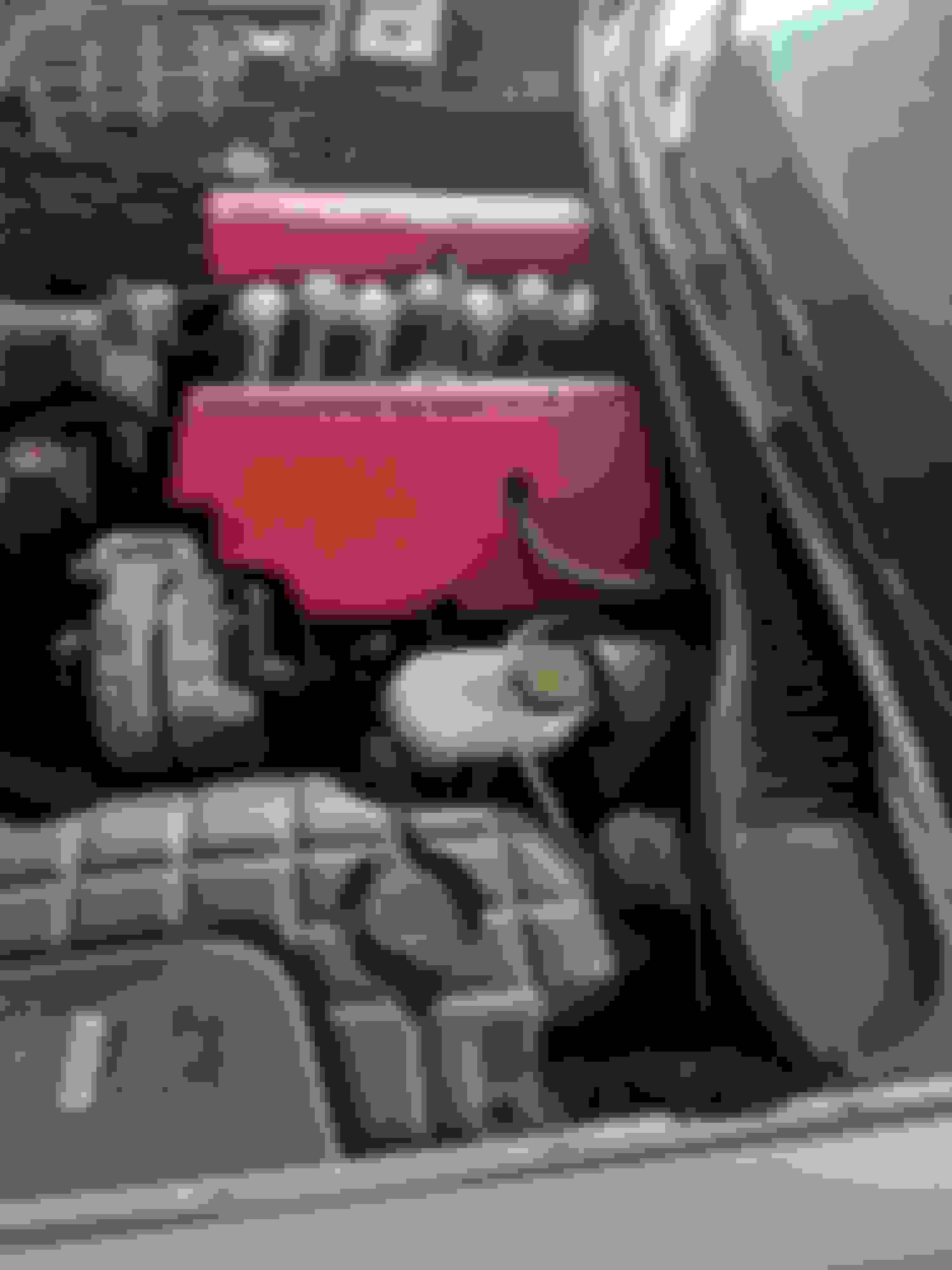
DeWitts radiator with EOC and improved racing adaptor with 212 tstat
My factory 20 year old radiator cracked. I decided to replace it with a 2 core DeWitts radiator with built in engine oil cooler. I also contacted improved racing and got their adaptor with a 212 thermostat and all the others parts needed to finish the install. More specifically heat shield for the nylon braided -10 line (7 foot of line and 6 foot of the heat shield) two x 90* -10 fitting, one x 45 * fitting, one x straight fitting, and self sealing tape. Excellent customer service from both companies. Also I have experienced maybe 1 to 2 psi drop in oil pressure @ idle but I never really watched it like a hawk, as I did after installing all this. Oil Temps come up to temp just as they did before had as well. Maybe a touch slower but no concerns to me.
Edit: part numbers used
To begin you need to put the car in the air. Use sky hooks if you got them. If not a lift or jack stands will work. Next disconnect the battery (5/16). Now drain the coolant and oil. The radiator drain is on the lower passenger had side. Is only turns 90*, so don't hulk out on it. Next unhook the MAF sensor and remove the air bridge (I used a flathead screwdriver for the clamps and the retaining pins on the air bridge) between the MAF and throttle body. With that removed use a 10mm to remove r the 4 bolts that hold the upper radiator support on to the frame.
Next use a pair of pliers to undo the spring clamps on the radiator hoses and undo them from the radiator. I removed the upper radiator hose completely but left the others in place. (After the water pump dripped on me a couple of times, I replaced the hose turned up like a snorkel so that I did not have to deal with the dripping anymore.) Also you may want to replace those spring clips with better hose clamp.
Next the fans need to be unpluged from the harness. The plugs are located under the fan motors. Now you can push the fan assembly up about 1/2 inch out of the brackets that hold it to the radiator and then from the top completely pull them out and set it aside. Clean them up while they are out as well. Same process for the ac condenser. Push the condeser up abut a half inch, however leaver the condenser hooked up so you don't have to refill the ac. It will stay in place and not be an issue. Now the radiator is free to come out the top. Don't toss it before you take the rubber isolators off the bottom of it. ( One per side and the driver side will probably remain on the lower brace.)
At this time I decided to leave the radiator out and move onto the oil cooler adaptor.
Here is the adaptor and the fittings for it. The top fitting is where the oil cooler sensor goes in. I reused the one on my engine. Lube all the fitting with oil on the treads and o-ring before threading them in. Do not over tighten these or it will trash the whole operation.
Don't freak out this is a busted engine that hasn't been to the crusher yet. It's out and easy to get pics with. The adaptor will replace the oil temp adaptor above the oil filter. Like so
You have to take the oil filter off to remover the old adaptor. Clean the area so you don't get trash in the oil system, do I really need to say this????? Two 10mm bolts hold the old adaptor onto the block. Unplug the oil temp sensor and remote it. I used a Cresent wrench to hold the old adaptor and a wrench to uncrew the sensor. Shame on me I did not write down the size now install the sensor in the new oil cooler adaptor. I used hi temp silicon to insure no leaks. The supplied gasket and bolts are needed at this time. A 5 mm Allen head is used to tighten the down to 112 inch lbs. Also oil the gasket so it doesn't get damaged. With the adaptor on now comes the fun stuff, routing the lines. Go crazy what ever you think is best go that route. I ran both lines in between the block and engine mount. It's a tight fit but they will go. I installed the fitting on one end of the -10 hose.
I printed off a funnel like tool (this is the top and bottom of the tool) to compress all the stray ends of the braid and allow the outer part of the fitting. Makes life easier. The hose will hit a ledge in the fitting before the threaded section. Mark the hose so you know that it has not slipped out of where it needs to be. Now with the outer part on the hose, oil the inside of the hose and the male portion of the fitting. Insert the fitting into the hose and press until you can start threading the fitting together. I used a vice to hold the hose as I made the fitting. Just a 4x4 drilled and cut in half.
I used a pair of sheers to cut the first end. The line has a steel band in it and it was not a very clean cut. So I ended up using a hack saw with the end tapped. I then flushed the hose and removed all the debris from it. To get the measurement of the line I ran the hose with one fitting on it at attached it to the adaptor then measured it to the oil cooler. In order to do that I had to place the radiator in the car to get the measurement. I still did not ateach it because I pulled it back out to modify the fan assembly. Anyways both my lines ended up right at 3 foot. There is a lot of back and forth, from underneath the car in this step. Getting the measurement and test fitting.
It's importantto note that once you cut the hose you have to install the heat shield over it before adding the second fitting. Or you'll be pulling it back off. With both lines made up I tapped up both ends with painters tape to keep it clean and then ran them from the back of the engine in between the block and engine mount. Under the rack and to the radiator.
If you are using the factory fan assembly you will have to cut away sections for the oil cooler in and out fittings. I used a dremel tool to cut the area out little by little and test fitting it. The upper driver side corned needs to be cut. The whole back seem needs to be shaved down (driver side only) and the bottom corner trimmed too. The tab that is on the 7 o'clock position of the driver side fan will be cut off. If you want more regitity rivit the ring to the bezel.
this pic is upside down
Now that everything is fitting right put the radiator back in and attach the ac condenser. Remember to use the rubber isolators off the old radiator. Now put the fan assembly in and attach the oil lines to the fittings on the radiator. I could no get oil to prefilled the cooler. I tried every trick I could think of and it just spilled everywhere. I would suggest buying a spare 90* fitting and using the excess hose to prefill the cooler. I had only the hose so I hooked it up without prefilling. To fill it I pulled the fuse to the fuel pump and turned the engine over or 3 seconds at a time and checking the oil level with the dip stick as well as looking for leaks in between each cycle. It took 5 or 6 times before the oil level did not drop or dropped a negligible amount. I used a little under 7 quarts plus what ever little bit if any made it in when trying to prefill.
Reinstall the upper radiator support, all radiator hoses, air bridge and plug in the maf. Start it up check for leaks, then double check for leaks and make sure you have the appropriate oil pressure. Congrats if it's not leaking your done.
Last edited by Proletariat designs; Sep 20, 2017 at 10:24 AM.
My old latches for the hatch did not register when the hatch was closed. Hence the curtousy lights would stay on and run the battery dead. So the fuse was pulled to prevent that. The springs that pop up the lid were weak and would not lift the trunk. I had to open and close a door to get it up. I bought a set of new model latches that have improved springs.
First unscrew the plastic nut with the hooks for the cargo net. And remove the side cover. Then the side storage cover needs to be removed. Now the side cover can be pulled out and the light slips off the top
Two or three 10mm bolts hold the latches to the backet. I guess if you remove the lights from the rear bumper, you could take the whole bracket off. Anyways I just swapped the actual latch
Unplug the two connectors and remove the old latch. Reinstall the new latch. With the bolts loose. And hook up the two connectors. Not you need to position the latch and lower the hatch to test the fit. After the fit feels right tighten the bolts down and reinstall the covers.
I did one side at a time to ensure that the latch held the trunk in like the old ones did.
Really simple, but now I have curtousy lights and on a dd that's amazing.
If you have a c5 at some point the column will lock on you. Mine did yesterday morning. I think it may have been the battery being weak bc I pulled the fuse to "shock" the system and it worked after that. Nonetheless this has been residing in my glove box incase it decided to leave me stranded I could install it on the go ( I would not recommend this but it is possible). Long story short if you buy this one the instructions are great. Everything you need to know or see is there. For those who want to see the process it's simple and takes 30 mins.
start by removing the kick panel that covers the bcm and fuse panel in the passenger floor. Remove the fuse panel cover as well. Then the key on and if the steering column unlocks remote fuse 23.
Trying to point out the location of the fuse.
Now remove the negative terminal on the battery (5/16 wrench). And replace fuse 23.
At this point I chose to listen to an episode of Ben Shapiro, don't just better your car but better yourself as well. Side note if your are not in the mug club or sport a tumbler, what are you doing with your life?????? This will let any power that may be stored in the electrical system bleed off.
Lift up from the bottom of the bcm and pull down and towards you once you get to about a 45* angle.
Now undo the connectors 3 in total ( the middle pink will not be modified).
Start with the green connector. And remove the blue piece. I used my fingernail, but a small screwdriver would work.
Insert the wire removal tool aka call Allen wrench into the top left corner.
It pushes in about 1/2 inch. And pull the orange wire out. Note the orientation of the metal pin. Insert the new one in the same way until it clicks in place.
Now do the same thing for thepin on the top row, third from the left.
Put in the new purple wire and insert the blue snap fitting.
Move the the top pink connector. Pull the green wire.
Now you plug the bcm in and attach the black wire to the bottom of the bcm where you pick up to remove it.
add the 5/16 lock nut and tighten it down. The bolt head is a 1/4. Now use the zip ties to secure the bypass to the wiring harness and secure the loose wires.
Put the bcm back in place and reconnect the battery. Test out to ensure it works..... no service column warning and no fuel shut off at 3 mph. Test it out a couple of times then fish up placing the fuse panel cover and kick panel. And it's done no more worries.
Here is how I fab up the cibie snout lights for my c5. The lights are anemic on my car. This cures it up.
So to start you need to put the car up on a lift or jack stands, and disconnect the battery. Use a 7mm and 10mm to remover the front bumper.
Use a Philip head screwdriver to remove the to screw holding the filler cover for the front plate. Use the plate to make a template of the bumper recess.
Cut it out and test fit it.
The cibie attach via a snap ring. So center the rings onto the template and make sure to have the cutout straight up and down not off set like I for some unknown reason decided to trace them out first.
I used some 3/4" tubing to make a bracket to mount to the frame and hold the lights. I used the cardboard template to get the dimensions. I made it so the the template will fit inside the frame.
those tabs will be on the bottom to use as an attachment point for a splitter once I get around to it. I may not need it, but if I do its there.
I cut a piece of sheet metal to the same size as the bracket and marked it just like the template.
Now I moved to the bumper.
I drilled the center point to use for the holesaw. (5 inch hole saw).
Now here is where I would suggest a different route then what I took. I drilled the bumper and looked to make sure it all lined up. I then tried to use these holes for mocking up the bracket. Just cut the recess out except for the thicker portion where the screws attack the filler plate.
With the center section cut out or the holes drilled you need to mark the Styrofoam impact bumper to cut out. For the bracket. There are screw that hold the bumper to the Styrofoam up top those have to come out as well. At this point the bumper is going to come off and on several times to check the fitment of the bracket.
Find the center line and mark out to the edge of the bracket on the Styrofoam. I used a Sawzall to cut out this section. I went a little small and then shaved off the side so as not to remove too much of the impact absorber.
I also notched the bottom of the Styrofoam so the the legs of the bracket will sit flush on the frame.
Now the bumper is back on but loose, as in not bolted in. Just getting an idea of where the legs need to be mounted on the bracket. Extra hands will make this lots easier. Now weld the legs onto the frame of the bracket.
I then used the same hole saw to cut out the hole on the sheet metal face. I then used red tin snips (right handed cuts) to cut out the top and bottom tabs. Then cleaned up all the cuts with a dremel and sanding stone. Then I primed and painted the whole thing. Once it dried, I rivited the the snap rings to the face of the bracket.
I drilled four holes on the back of the legs to bolt it to the frame. I used the passenger side rear hole to mark the frame. I then drilled and taped the frame for one hole. Mount the bracket with that one bolt and mark, drill, and tap the other 3 holes. Do one at a time so that any shifting will not be an issue.
I 3d printed some rubber washers to help absorb a little of the shock from these rough roads. They go in between the frame and the legs of the bracket. I also used lock washers to keep the bolts tight. There's not alot to tap into on the frame.
The brackets are on and it's starting to come together.
Now it's time to wire the thing up. I used 12 gauge marine grade wire. I ran both grounds to the passenger side and drilled and tapped them to the frame. For the power supply I used a relay and inli e fuse to supply the power via 12 gauge Maine grade. I used a signal wire from the bright lights to control the relay. I tapped into the passenger side bright light wire (tan and light green wire) before the connector at the headlight. I ran the wires along side the passenger side frame rail into the battery compartment in 3/8" flex tubing to keep it looking clean.
In the battery compartment I used velcro to mount the relay and in line 20amp fuse (sealed marine grade) to the side of the fender. I cut a slit in the battery boot and used a ring terminal to attach directly to the posite terminal.
This is my rough draft for wiring up the relay. Will make a better pic in a bit.
(Insert pic here)
The ground from the relay is routed into the cab and a toggle switch was added so that I can use the bright lights without the driving lights. From the toggle I grounded it to a bolt under the console. My brother designed a piece to replace the ash tray for the swith to keep the inside looking clean.
So now it's wired up. I tested it out and admired my work. Then disconnected the battery again.
Now tape up around the recess in the bumper and cut it out how you think is best. I used a dremel and it worked ok.
I left a lip around the edge to help hold the clear bumper filler in place. Then use some black door edge molding to clean it up.
Reinstall he bumper and massage all the lines to make it flush with the fenders. Hook up the batter and check it out.
Shameless amount of photos of the end product.
The look I was inspired by....


 now install the sensor in the new oil cooler adaptor. I used hi temp silicon to insure no leaks. The supplied gasket and bolts are needed at this time. A 5 mm Allen head is used to tighten the down to 112 inch lbs. Also oil the gasket so it doesn't get damaged. With the adaptor on now comes the fun stuff, routing the lines. Go crazy what ever you think is best go that route. I ran both lines in between the block and engine mount. It's a tight fit but they will go. I installed the fitting on one end of the -10 hose.