
DETAILED BUSHING and COIL OVER install info
 03-24-2011, 01:23 AM
#1
Race Director


Thread Starter
Member Since: Apr 2004
Location: Bronson FL
Posts: 16,135
Likes: 0
Received 3 Likes
on
3 Posts
Cruise-In VIII Veteran
St. Jude Donor '07

Okay, I recently installed Pfadt bushings (front and rear) and the LG GT2 Coil Overs and want to attempt a nice little thread to help with little problems a guy doing this in his garage might have.
So, I am going to try and make this worthwild.
Tools...
- 18-24mm (both box and rachet)
- Hammer (both rubber and standard hammers)
- Alan wrenches (Metric)
- Pickle Fork - (this will help, but not a necessity)
- Torque Wrench (at least a 150, but a 250 foot pound would be very useful)
- HIGH QUALITY Grease (Blue Ray Marine is the preferred, but Mobil Syntheic (red in color) is good stuff also. Super High Pressure bearing grease. Don't use the junk that is sent.)
- Zip Ties (to help hold things out of the way. i.e. Calipers)
- Breaker bar
- Red Lock tite
- Grinder (to grind down the bushings)
- Quality tape measure or mechinists ruler
STEP 1.
Get the car in the air, via a lift or jack stands. Thankfully I had access to a lift, but you can do the job on jack stands, but it will take more time. Just be patient.
STEP 2.
Remove the wheels and remove the caliper brackets (21mm - I believe)(use the zip ties to hang them out of the way). You could remove the Tie Rod nut (18mm) to allow you to move the hub out of the way to get to the Caliper Bolts easier. Remove the rotors. BE CAREFUL of the brake lines when moving things around.
STEP 3.
I am going to start with the rear, because this is actually the more difficult of the two.
You need to go ahead and remove the following items:
LOWER Sway Bar endlink nut (18mm)
Remove the Sway bar (17mm - to remove)
TIE ROD nut (18mm)
Take the lower Shock Bolt and nut and break these loose (24mm)
Upper Ball Joint nut (18mm)
Break loose the Lower Ball Joint nut (21mm - if I recall correctly)
Remove the SPRING bolts and nuts.
TIP - When you remove the the Lower Ball Joint Nut, you will need to either use the Pickle Fork (careful not to rip the boot - like I did) to pop the ball joint away from the lower control arm. I later found that taking a hammer (standard) and just tapping down on the arm worked better and saved me from buying a new ball joint. Doing this will help seperate the lower control arm from the spindle. Ensure that you have backed the ball joint nut as far as you can to ensure adequate space when popping the two apart. Now that you have things loose, go ahead and remove the nut.
Go ahead and remove Upper A Arm (18mm) and the Upper Shock Bolts (13mm)
MARK the CAMBER BOLTS/WASHERS prior to removing. This will allow you to get somewhat of a driveable alignment once install has been completed.
Once you have the lower control arm ball joint nuts removed go ahead and remove the spring. Then carefully loosen the CAMBER bolts, because the a arm may swing down and smack you (it happened to my buddy). Go ahead and remove the a arm. You may mark them DRIVER and PASSENGER side to make sure when you re-install them you get them back in on the right side. Trust me, there is only one way to install them correctly.
RECOMMEND that when you remove nuts and bolts you take them and put them on the parts taken off the car to prevent from mixing them up or loosing them.
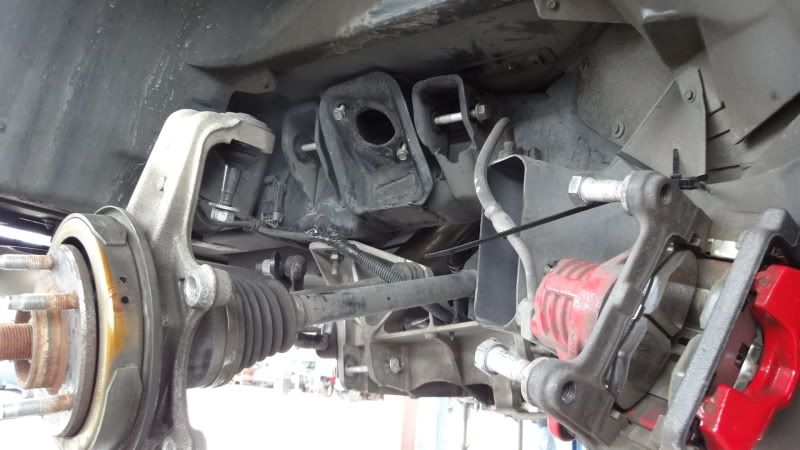
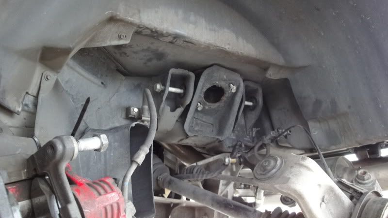
Here are a few pictures of what this should look like once all of this is removed.
Here is the wheel, caliper and rotor removed. Noticed how I zip tied things out of the way. Notice that the Upper A Arm has been removed as well as he shock. I also zip tied the OUTPUT Shaft to prevent to much pressure on it just hanging there through the install.


STEP 4 - Bushing removal. Okay, I went ahead and paid to have the stock rubber bushings removed. I did this to save time and aggreviation. I heard they can be quite the challenge and I felt less headaches was worth the price to have them removed. Plus, I tore up a boot on one of my lower ball joints and need that installed.
STEP 5 - Bushing install. This is tricky. First, measure the opening on the cradle. Take the bushings and washers and compare the width measured to ensure that they are the same. What this means is, piece them together as the instructions provided show and measure the length (width) and take that measurement and compare to the cradle opening measurement. If not the same (and they won't be), you will need to grind them down. Some have cut the solid bushings in half and grinded them to fit. I choose to grind them down instead of cutting them. I spoke with Pfadt and Aaron said to grind the end down. I choose to grind the flat (very thick) area on the forward lower control arm bushing. This bushing is rounded on one side and flat on the other. Once you have a close measurement you are ready to install.
You will noticed that the stock bushings were not nearly as wide as they are when you install the setup prior to cutting/grinding them down. See pictures below.


STEP 6 - Inserting the bushings into the control arms. The lower arm is going to require a vice or some sort of press. You will also need a large socket that is a similiar diameter as the hole on the lower control arm. Take your time and I recommend having a friend help. Be careful not to put any amount of strain on the arms themself. With a nice vice, these will work into the opening on the control arm nicely. The upper arm is simple and did not require a vice or grinding.
STEP 7 - Ensure to lube these up nicely. Do not be afraid to use a ample amount of lube. Whatever comes out later you can clean up with rags and brake cleaner or something. Assemble the arms completely and prepare for install.
SEE NEXT POST for MORE!
So, I am going to try and make this worthwild.
Tools...
- 18-24mm (both box and rachet)
- Hammer (both rubber and standard hammers)
- Alan wrenches (Metric)
- Pickle Fork - (this will help, but not a necessity)
- Torque Wrench (at least a 150, but a 250 foot pound would be very useful)
- HIGH QUALITY Grease (Blue Ray Marine is the preferred, but Mobil Syntheic (red in color) is good stuff also. Super High Pressure bearing grease. Don't use the junk that is sent.)
- Zip Ties (to help hold things out of the way. i.e. Calipers)
- Breaker bar
- Red Lock tite
- Grinder (to grind down the bushings)
- Quality tape measure or mechinists ruler
STEP 1.
Get the car in the air, via a lift or jack stands. Thankfully I had access to a lift, but you can do the job on jack stands, but it will take more time. Just be patient.
STEP 2.
Remove the wheels and remove the caliper brackets (21mm - I believe)(use the zip ties to hang them out of the way). You could remove the Tie Rod nut (18mm) to allow you to move the hub out of the way to get to the Caliper Bolts easier. Remove the rotors. BE CAREFUL of the brake lines when moving things around.
STEP 3.
I am going to start with the rear, because this is actually the more difficult of the two.
You need to go ahead and remove the following items:
LOWER Sway Bar endlink nut (18mm)
Remove the Sway bar (17mm - to remove)
TIE ROD nut (18mm)
Take the lower Shock Bolt and nut and break these loose (24mm)
Upper Ball Joint nut (18mm)
Break loose the Lower Ball Joint nut (21mm - if I recall correctly)
Remove the SPRING bolts and nuts.
TIP - When you remove the the Lower Ball Joint Nut, you will need to either use the Pickle Fork (careful not to rip the boot - like I did) to pop the ball joint away from the lower control arm. I later found that taking a hammer (standard) and just tapping down on the arm worked better and saved me from buying a new ball joint. Doing this will help seperate the lower control arm from the spindle. Ensure that you have backed the ball joint nut as far as you can to ensure adequate space when popping the two apart. Now that you have things loose, go ahead and remove the nut.
Go ahead and remove Upper A Arm (18mm) and the Upper Shock Bolts (13mm)
MARK the CAMBER BOLTS/WASHERS prior to removing. This will allow you to get somewhat of a driveable alignment once install has been completed.
Once you have the lower control arm ball joint nuts removed go ahead and remove the spring. Then carefully loosen the CAMBER bolts, because the a arm may swing down and smack you (it happened to my buddy). Go ahead and remove the a arm. You may mark them DRIVER and PASSENGER side to make sure when you re-install them you get them back in on the right side. Trust me, there is only one way to install them correctly.
RECOMMEND that when you remove nuts and bolts you take them and put them on the parts taken off the car to prevent from mixing them up or loosing them.
Here are a few pictures of what this should look like once all of this is removed.
Here is the wheel, caliper and rotor removed. Noticed how I zip tied things out of the way. Notice that the Upper A Arm has been removed as well as he shock. I also zip tied the OUTPUT Shaft to prevent to much pressure on it just hanging there through the install.
STEP 4 - Bushing removal. Okay, I went ahead and paid to have the stock rubber bushings removed. I did this to save time and aggreviation. I heard they can be quite the challenge and I felt less headaches was worth the price to have them removed. Plus, I tore up a boot on one of my lower ball joints and need that installed.
STEP 5 - Bushing install. This is tricky. First, measure the opening on the cradle. Take the bushings and washers and compare the width measured to ensure that they are the same. What this means is, piece them together as the instructions provided show and measure the length (width) and take that measurement and compare to the cradle opening measurement. If not the same (and they won't be), you will need to grind them down. Some have cut the solid bushings in half and grinded them to fit. I choose to grind them down instead of cutting them. I spoke with Pfadt and Aaron said to grind the end down. I choose to grind the flat (very thick) area on the forward lower control arm bushing. This bushing is rounded on one side and flat on the other. Once you have a close measurement you are ready to install.
You will noticed that the stock bushings were not nearly as wide as they are when you install the setup prior to cutting/grinding them down. See pictures below.
STEP 6 - Inserting the bushings into the control arms. The lower arm is going to require a vice or some sort of press. You will also need a large socket that is a similiar diameter as the hole on the lower control arm. Take your time and I recommend having a friend help. Be careful not to put any amount of strain on the arms themself. With a nice vice, these will work into the opening on the control arm nicely. The upper arm is simple and did not require a vice or grinding.
STEP 7 - Ensure to lube these up nicely. Do not be afraid to use a ample amount of lube. Whatever comes out later you can clean up with rags and brake cleaner or something. Assemble the arms completely and prepare for install.
SEE NEXT POST for MORE!
Last edited by mph1972; 03-28-2011 at 04:34 PM.
 03-24-2011, 01:46 AM
#2
Race Director
Thread Starter
Member Since: Apr 2004
Location: Bronson FL
Posts: 16,135
Likes: 0
Received 3 Likes
on
3 Posts
Cruise-In VIII Veteran
St. Jude Donor '07
STEP 8 - Swap out your SWAY BAR bushings and install it. Only apply the mounting bolts on the car loosely. You will need to be able to remove the lower bolt to ensure you can mount the lower control arm.
STEP 9 - Install the LOWER CONTROL ARM. This will take some effort and a little help from the rubber mallet. Once you get them in go ahead and tighten them down. Make sure you line the marks up that you made earlier. This will help you with the alignment. Go ahead and ensure the bolts are clean of any grease and then apply some lochtite. I used RED lochtite on everything. The torque specs for these are as follows:
107 lb ft - FRONT
70 lb ft - REAR
Here is a picture of what the bushing looks like snuggly in place...

STEP 10 - Install the UPPER CONTROL ARM. These are much easier than the LOWER, but could possibly need the rubber mallet also. Once you have them in, go ahead and torque them to the following specs.
81 lb ft for both.

Now, you need to grab the coil overs.
STEP 11 - Go ahead and attach the ride stiffness cable appropriately. You need to take the COIL and back out the lower portion of the shock. It shouldn't be that difficult. You may need to take the spanner wrench provided with the coil overs, just pop loose the bottom ring and I backed out the lower portion of the coil over 2". You can set the stiffness level prior to install. I set it to six. Once you have these prepped and ready to go, install only the top portion. Once you have the bolts in on the top, torque the bolts down to:
22 lb ft
MORE COMING...See the next thread.
STEP 9 - Install the LOWER CONTROL ARM. This will take some effort and a little help from the rubber mallet.
Once you get them in go ahead and tighten them down. Make sure you line the marks up that you made earlier. This will help you with the alignment. Go ahead and ensure the bolts are clean of any grease and then apply some lochtite. I used RED lochtite on everything. The torque specs for these are as follows:107 lb ft - FRONT
70 lb ft - REAR
Here is a picture of what the bushing looks like snuggly in place...
STEP 10 - Install the UPPER CONTROL ARM. These are much easier than the LOWER, but could possibly need the rubber mallet also. Once you have them in, go ahead and torque them to the following specs.
81 lb ft for both.
Now, you need to grab the coil overs.
STEP 11 - Go ahead and attach the ride stiffness cable appropriately. You need to take the COIL and back out the lower portion of the shock. It shouldn't be that difficult. You may need to take the spanner wrench provided with the coil overs, just pop loose the bottom ring and I backed out the lower portion of the coil over 2". You can set the stiffness level prior to install. I set it to six. Once you have these prepped and ready to go, install only the top portion. Once you have the bolts in on the top, torque the bolts down to:
22 lb ft
MORE COMING...See the next thread.
03-24-2011, 02:32 AM
#3
Race Director
Thread Starter
Member Since: Apr 2004
Location: Bronson FL
Posts: 16,135
Likes: 0
Received 3 Likes
on
3 Posts
Cruise-In VIII Veteran
St. Jude Donor '07
STEP 12 - Mount the UPPER CONTROL ARM ball joint to the spindle. You can go ahead and find the correct alan wrench size to help the tightening process to be easier. Once it presses itself in, the alan will no longer be necessary. The torque on this nut will be:
1st Pass - 15 lb ft
2nd Pass - 250 degrees
3rd Pass - 41 lb ft
NOTE - We tighten this pretty tight and then went straight to the 41 lb ft. And of course, RED lochtite on everything.
STEP 13 - This is probably the MOST difficult STEP of them ALL!!! You will want to kill someone when doing this step. So, take your time, grab something to drink, take a break if you need too, this will be a challenge if you are not working with every tool in the tool box. Find the proper alan wrench for this and prepare to modify it. Trust me, unless you know of a better way, this modification is going to help A LOT!
LOWER CONTROL NUT. Start it up (with RED lochtite on it) and titghten as much as you can. You will then work the modified Alan wrench into place. See mine below:

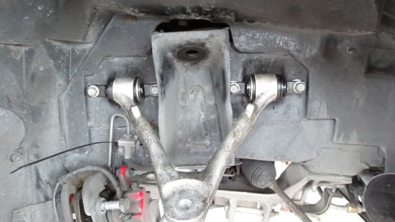
Okay, now hold it securely. Below is what I did to prevent it from moving.

Now, you are suppose to torque this to the following specifications:
1st Pass - 15 lb ft
2nd Pass - 3.5 flats
3rd Pass - 52 lb ft
Good luck my friends. What I did was tighten it as tight as I possible could!
If you have made it this far, it will look something like this and you should pat yourself on the back, because it is quite a challenge.

Now, it is time to just tighten everything down. I would do it in this order.
TIGHTEN the bottom of the COIL OVER. Torque it to 162 lb ft. I recommend using a 250 lb ft torque wrench to ensure it is tighten, but you can use a 150 lb ft and just torque on it a little extra if you need too.
Now, go ahead and tighten the SWAY BAR down, leave the endlinks alone until you have the opposite side all connected and tighten down. The torque specs for the upper bolts on the cradle is 49 lb ft. The lower bolt is already torqued.
Keep the Tie Rod nut off, so you can give yourself extra space to install the CALIPER.
Mount your rotor and take the caliper and get the bolts started. Once you have them started you need to torque them down to 125 lb ft. If you paid attentioned to me and did not tighten the tie rod nut, you can turn the caliper a little and give you more room to torque these down properly.
Once you have completely tighten these down, tighten the tie rod nuts down to following:
1st Pass - 15 lb ft
2nd Pass - 160 degrees
3rd Pass - 33 lb ft
Again, I just tighten them down good and tight and then torqued them down to 33 lb ft.
Now, make sure you connect the ABS connections all back up and then torque the SWAY BAR Endlink nuts down to 53 lb ft.
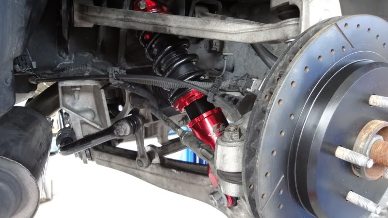

Here are the pictures after I got the coil over backed out and shows the actually gap, because I found out the hard way that they need to be backed out, because the car was SLAMMED before I did the backing out...


Okay, this completes the rear.
NOTE: I am not a MASTER MECHANIC and recommend you also read the instructions to the products. I am not responsible for anything that may break and make sure you check everything TWICE to ensure all is connected and torqued down!
Now off to do the fronts. I will post those details up tomorrow.
1st Pass - 15 lb ft
2nd Pass - 250 degrees
3rd Pass - 41 lb ft
NOTE - We tighten this pretty tight and then went straight to the 41 lb ft. And of course, RED lochtite on everything.
STEP 13 - This is probably the MOST difficult STEP of them ALL!!! You will want to kill someone when doing this step. So, take your time, grab something to drink, take a break if you need too, this will be a challenge if you are not working with every tool in the tool box. Find the proper alan wrench for this and prepare to modify it. Trust me, unless you know of a better way, this modification is going to help A LOT!
LOWER CONTROL NUT. Start it up (with RED lochtite on it) and titghten as much as you can. You will then work the modified Alan wrench into place. See mine below:
Okay, now hold it securely. Below is what I did to prevent it from moving.
Now, you are suppose to torque this to the following specifications:
1st Pass - 15 lb ft
2nd Pass - 3.5 flats
3rd Pass - 52 lb ft
Good luck my friends. What I did was tighten it as tight as I possible could!
If you have made it this far, it will look something like this and you should pat yourself on the back, because it is quite a challenge.
Now, it is time to just tighten everything down. I would do it in this order.
TIGHTEN the bottom of the COIL OVER. Torque it to 162 lb ft. I recommend using a 250 lb ft torque wrench to ensure it is tighten, but you can use a 150 lb ft and just torque on it a little extra if you need too.
Now, go ahead and tighten the SWAY BAR down, leave the endlinks alone until you have the opposite side all connected and tighten down. The torque specs for the upper bolts on the cradle is 49 lb ft. The lower bolt is already torqued.
Keep the Tie Rod nut off, so you can give yourself extra space to install the CALIPER.
Mount your rotor and take the caliper and get the bolts started. Once you have them started you need to torque them down to 125 lb ft. If you paid attentioned to me and did not tighten the tie rod nut, you can turn the caliper a little and give you more room to torque these down properly.
Once you have completely tighten these down, tighten the tie rod nuts down to following:
1st Pass - 15 lb ft
2nd Pass - 160 degrees
3rd Pass - 33 lb ft
Again, I just tighten them down good and tight and then torqued them down to 33 lb ft.
Now, make sure you connect the ABS connections all back up and then torque the SWAY BAR Endlink nuts down to 53 lb ft.
Here are the pictures after I got the coil over backed out and shows the actually gap, because I found out the hard way that they need to be backed out, because the car was SLAMMED before I did the backing out...
Okay, this completes the rear.
NOTE: I am not a MASTER MECHANIC and recommend you also read the instructions to the products. I am not responsible for anything that may break and make sure you check everything TWICE to ensure all is connected and torqued down!
Now off to do the fronts. I will post those details up tomorrow.
Last edited by mph1972; 03-24-2011 at 03:38 AM.
03-24-2011, 02:37 AM
#4
Safety Car

I made one of those allen tools too, works well.
My mom remove the rubber bushings, you just need a large C clamp and some fittings from a ball joint install kit.
One perk of cutting the bushings in half is that installing them in the arm is a piece of cake.
My mom remove the rubber bushings, you just need a large C clamp and some fittings from a ball joint install kit.
One perk of cutting the bushings in half is that installing them in the arm is a piece of cake.
03-24-2011, 03:08 AM
#5
Race Director
Thread Starter
Member Since: Apr 2004
Location: Bronson FL
Posts: 16,135
Likes: 0
Received 3 Likes
on
3 Posts
Cruise-In VIII Veteran
St. Jude Donor '07
Okay, the fronts were easier than the rear. At least, I thought so.
Now, this post will not be the same as the rear, because you have an idea of what needs to be done to remove everything. So, remove the sway bar...PAY ATTENTION to how it was mounted, it can be tricky getting it back on if you did not pay attention as to how it was on in the first place.
Remove the CALIPER and ROTOR. Here is a picture of how I zip tied it up.

Okay, got that out of the way. Go ahead and swap out the bushings on the sway bar (that is if you got them). Put it off to the side, you won't need it for a while.
Begin loosing up everything, remove the steering rod and move it over (see above picture). I then removed the lower bolts to the shock and loosened the nuts to the upper and lower control arm.
Once you have loosened them, you can remove the spindle. I marked them D - Driver and P - for you guessed it - Passenger.
Now you can remove the spring and mark the camber bolts. MAKE sure you mark these, because steering will be interesting if you don't have any marks to get the camber setup.
If you have adequate marks, go away and remove the lower control arm. I can't remember the size of the nuts and bolts, but if you have the tools I listed, you are covered.
You should have the shock and upper control arm. To gain access to the upper nut holding the shock in, there are a few 10 mm bolts holding the coolant resovior (sp?) and the wind shield wiper fluid tank. You don't need to disconnect the hose, just carefully move them to the side. I believe the nut is a 24 mm (I know the one installing the LG Coil Overs are 24 mm).
Go ahead and remove the upper control arm. NOTE! You may find that there are washers behind the bolts. MAKE SURE you remember what went where, these are important! I took them off, removed the control arm and then put the bolts right back where they came from. Doing this for everything helps!
It will look a lot like the above picture.
Now, I took all of my control arms and had a shop remove the bushings and installing this bushings were pretty easy, however the lower control arm needed some modification. Remember what I told you to do on the rear lower control arm? You will need to do the same.
Measure the cradle opening and then weasure the assembled bushing and washer setup. Make sure you make the proper measurements, because you will need to grind/sand the ends down to make them work. I choose to grind down the flat surfaces! I think I took about a 1/4 inch off.
Sorry I don't have more pictures, but I am going to continue in the next post.
Now, this post will not be the same as the rear, because you have an idea of what needs to be done to remove everything. So, remove the sway bar...PAY ATTENTION to how it was mounted, it can be tricky getting it back on if you did not pay attention as to how it was on in the first place.
Remove the CALIPER and ROTOR. Here is a picture of how I zip tied it up.
Okay, got that out of the way. Go ahead and swap out the bushings on the sway bar (that is if you got them). Put it off to the side, you won't need it for a while.
Begin loosing up everything, remove the steering rod and move it over (see above picture). I then removed the lower bolts to the shock and loosened the nuts to the upper and lower control arm.
Once you have loosened them, you can remove the spindle. I marked them D - Driver and P - for you guessed it - Passenger.
Now you can remove the spring and mark the camber bolts. MAKE sure you mark these, because steering will be interesting
if you don't have any marks to get the camber setup. If you have adequate marks, go away and remove the lower control arm. I can't remember the size of the nuts and bolts, but if you have the tools I listed, you are covered.
You should have the shock and upper control arm. To gain access to the upper nut holding the shock in, there are a few 10 mm bolts holding the coolant resovior (sp?) and the wind shield wiper fluid tank. You don't need to disconnect the hose, just carefully move them to the side. I believe the nut is a 24 mm (I know the one installing the LG Coil Overs are 24 mm).
Go ahead and remove the upper control arm. NOTE! You may find that there are washers behind the bolts. MAKE SURE you remember what went where, these are important! I took them off, removed the control arm and then put the bolts right back where they came from. Doing this for everything helps!
It will look a lot like the above picture.
Now, I took all of my control arms and had a shop remove the bushings and installing this bushings were pretty easy, however the lower control arm needed some modification. Remember what I told you to do on the rear lower control arm? You will need to do the same.
Measure the cradle opening and then weasure the assembled bushing and washer setup. Make sure you make the proper measurements, because you will need to grind/sand the ends down to make them work. I choose to grind down the flat surfaces! I think I took about a 1/4 inch off.
Sorry I don't have more pictures, but I am going to continue in the next post.
03-24-2011, 03:35 AM
#6
Race Director
Thread Starter
Member Since: Apr 2004
Location: Bronson FL
Posts: 16,135
Likes: 0
Received 3 Likes
on
3 Posts
Cruise-In VIII Veteran
St. Jude Donor '07
Now, let's get those bushings assembled. Remember the measurements! Now, the install on the front seems to be a breeze, but once you get those bushings measured out, you will need to grab that trusty old rubber mallet.
Okay, I installed the upper arm after I assembled them and lubed them up really good. Torque those bolts down to:
48 lb ft
Now, you can focus on the lower control arms. You have them assembled with a good deal of lube. Take them and tap those bad boys in. Take your time, if you sanded/grinded them down correctly, it shouldn't take much. You need to take those camber bolts and nuts and ensure you put the fronts in the front hole and the rears in the rear holes. If you do not, let me know how driving it the first time was.
 Okay, line those marks up and let's torgue them down!
125 lb ft for the front and rear.
Okay, the front COIL OVER. It is basically the same concept as the rear. Loosen the bottom ring with the spanner wrench and back it out. I did it about an inch and a half.
Now, the bottom of the Coil Over was tought to twist, so I recommend you mount it to the lower control arm and that will allow you to move it around and then you can pull it up and position it into the upper hole. You can torque the bottom bolts to 21 lb ft. DO NOT tighten the upper yet, leave it loose, so just put the washer and nut on and leave it alone right now.
It will look alot like this. NOW, please note, that when I originally did the install I did NOT back out the lower portions of any of the coil overs. So, this picture represents the coil over in the state I recieved it.

This is what the gap should look like.

Okay, next post will include the rest of the install...
Okay, I installed the upper arm after I assembled them and lubed them up really good. Torque those bolts down to:
48 lb ft
Now, you can focus on the lower control arms. You have them assembled with a good deal of lube. Take them and tap those bad boys in. Take your time, if you sanded/grinded them down correctly, it shouldn't take much.
You need to take those camber bolts and nuts and ensure you put the fronts in the front hole and the rears in the rear holes. If you do not, let me know how driving it the first time was. Okay, line those marks up and let's torgue them down!125 lb ft for the front and rear.
Okay, the front COIL OVER. It is basically the same concept as the rear. Loosen the bottom ring with the spanner wrench and back it out. I did it about an inch and a half.
Now, the bottom of the Coil Over was tought to twist, so I recommend you mount it to the lower control arm and that will allow you to move it around and then you can pull it up and position it into the upper hole. You can torque the bottom bolts to 21 lb ft. DO NOT tighten the upper yet, leave it loose, so just put the washer and nut on and leave it alone right now.
It will look alot like this. NOW, please note, that when I originally did the install I did NOT back out the lower portions of any of the coil overs. So, this picture represents the coil over in the state I recieved it.
This is what the gap should look like.
Okay, next post will include the rest of the install...
03-24-2011, 04:03 AM
#7
Race Director
Thread Starter
Member Since: Apr 2004
Location: Bronson FL
Posts: 16,135
Likes: 0
Received 3 Likes
on
3 Posts
Cruise-In VIII Veteran
St. Jude Donor '07
Now it is time for the spindle to be re-installed. Recommend you put in the bottom ball joint and then the upper ball joint. Trust me, it is easier that way.
Thankfully the design in the front is not the same as the rear, because it is easier to get the Alan Wrench in the hole. Add your RED lochtite and tighten these two nuts in.
LOWER:
1st Pass - 15 lb ft
2nd Pass - 210 degrees
3rd Pass - 52 lb ft
UPPER:
1st Pass - 15 lb ft
2nd Pass - 250 degrees
3rd Pass - 41 lb ft
Great news, the tough parts are pretty much done, but you need to keep your eye on the prize and focus. You still have a few things left.
Get the ROTOR and put it on and then take your calipers and bolts and torque them on. I recommend not touching the steering rod and this will give you "swing" room and ensuring a little more torque room for the bolts. So, tighten them on and torque them to...
125 lb ft
Install the the steering rod (actually the steering linkage outer tie rod end stud nut) and torque these down with the assistance of the Alan Wrench:
1st Pass - 15 lb ft
2nd Pass - 160 degrees
3rd Pass - 33 lb ft
Connect the ABS connector before you forget.
Let's go ahead and tighten down the upper nut of he Coil Over. Do not let it spin. I used a large pry bar. It allowed me to pry against the large nut and prevent it from moving. Go slow and you should be fine.
19 lb ft
Wow, that was much easier than the rear, but you have the SWAY BAR to get on the car.
Do you remember how it went on there? Go ahead and tighten up the mounting brackets and torque it down to 43 lb ft.
Now get the end links in their place and tighten them down. I did not mention this in the rear, but if you are having issues with the Alan Wrench, you could take a opened end wrench and fit it the flat area on the back of the end link. It looks round, but there is a flat spot to allow you to take that opened end wrench to it and tighten it down. Torque it to 53 lb ft.
Again, I am not a MASTER MECHANIC, I just wanted to provide my input and experiences. I know TOQUE and others have provided input and they helped me out a great deal, but I still ran into a couple of things that I was not aware of, but hey if this helps one person that makes it worth it.
See pictures of my ride below. I keep it a little higher than some most, but I needed more clearance than I had, because of the driving conditions here. With these bushings from Pfadt, Coil Overs from LG (GT2 series), and an alignment by Scotty the car is amazing and feels great!
03-24-2011, 04:08 AM
#8
Race Director
Thread Starter
Member Since: Apr 2004
Location: Bronson FL
Posts: 16,135
Likes: 0
Received 3 Likes
on
3 Posts
Cruise-In VIII Veteran
St. Jude Donor '07
Full side view...

PASS - REAR
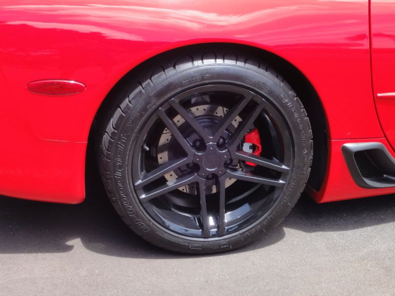
PASS - FRONT

DRIVER - FRONT
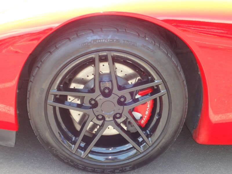
DRIVER - REAR
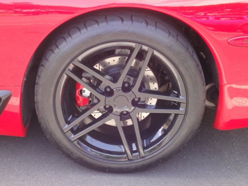
Now I adjusted the Coil Overs to be around a 1/4 higher on the driver side so when I am in it the car sits about 4.25 in the front and 4.5 in the rear and I measured at the jacking points. This is just an idea.
Okay, if you have any questions or suggestions on my post, let me know.
Thanks everyone for letting me share.
Micah
PASS - REAR
PASS - FRONT
DRIVER - FRONT
DRIVER - REAR
Now I adjusted the Coil Overs to be around a 1/4 higher on the driver side so when I am in it the car sits about 4.25 in the front and 4.5 in the rear and I measured at the jacking points. This is just an idea.
Okay, if you have any questions or suggestions on my post, let me know.
Thanks everyone for letting me share.
Micah


 07-22-2011, 10:44 PM
#11
Racer

Member Since: Mar 2008
Location: Mesa AZ
Posts: 445
Likes: 0
Received 0 Likes
on
0 Posts
Great write up!! I sure could of used this info last week! I had the same issue with the rear lower control arm bushing being too wide to fit into the cradle.(my thread:http://forums.corvetteforum.com/c5-t...t-install.html) I didnt realize there would be an issue with the fit until I had already pressed the bushings in... Pfadt told me that I was not suppose to take any material off the sides and that it had to be removed from the middle, which contradicts what they told you. I sure wish I had known I could remove the material from the outside it would of saved me a week of downtime.
I was made to believe this was not a common issue and that it wasn't the bushing but the lower control arm bore diameter but it seems this is not the case. They should really of made the bushing in a 2piece design from the start IMO. This thread will definitely save somebody a future bushing headache hopefully!
I was made to believe this was not a common issue and that it wasn't the bushing but the lower control arm bore diameter but it seems this is not the case. They should really of made the bushing in a 2piece design from the start IMO. This thread will definitely save somebody a future bushing headache hopefully!
07-23-2011, 12:24 AM
#12
Race Director
Thread Starter
Member Since: Apr 2004
Location: Bronson FL
Posts: 16,135
Likes: 0
Received 3 Likes
on
3 Posts
Cruise-In VIII Veteran
St. Jude Donor '07
Great write up!! I sure could of used this info last week! I had the same issue with the rear lower control arm bushing being too wide to fit into the cradle.(my thread:http://forums.corvetteforum.com/c5-t...t-install.html) I didnt realize there would be an issue with the fit until I had already pressed the bushings in... Pfadt told me that I was not suppose to take any material off the sides and that it had to be removed from the middle, which contradicts what they told you. I sure wish I had known I could remove the material from the outside it would of saved me a week of downtime.
I was made to believe this was not a common issue and that it wasn't the bushing but the lower control arm bore diameter but it seems this is not the case. They should really of made the bushing in a 2piece design from the start IMO. This thread will definitely save somebody a future bushing headache hopefully!
I was made to believe this was not a common issue and that it wasn't the bushing but the lower control arm bore diameter but it seems this is not the case. They should really of made the bushing in a 2piece design from the start IMO. This thread will definitely save somebody a future bushing headache hopefully!
 07-24-2011, 12:23 PM
#13
Racer
Member Since: Mar 2008
Location: Mesa AZ
Posts: 445
Likes: 0
Received 0 Likes
on
0 Posts
Glad it got done, sorry you spent more time on it than you wanted. I will say this, I am curious why they would say not to do it to you and for me to do it and that it is not a common thing and when I spoke with them, it seemed like it was regular occurrence when I spoke with them.
How much material did you grind off? I sawed down about 1/8'' material off the centers in order to get mine to fit.
I will say that the car handles AMAZING after the install and that all of the headache and work was definitely worth it in my case. I've had the Pfadt coilovers for over 2 years and the difference between stock bushings and the pfadt polly bushings is phenomenal. I'd say the increase in handling is as much as when I installed the coilovers over stock suspension. Best money i've spent on the car next to the coilovers FOR SURE. i'd also suggest replacing your rear sway bar bushing with a polly set since you are back there with the sway disconnected.
Last edited by enigma94; 07-24-2011 at 12:26 PM.
07-24-2011, 04:19 PM
#14
Race Director
Thread Starter
Member Since: Apr 2004
Location: Bronson FL
Posts: 16,135
Likes: 0
Received 3 Likes
on
3 Posts
Cruise-In VIII Veteran
St. Jude Donor '07
It wouldn't of been as bad If I had not of had to wait for the email from them (since they never answer their tech line) and had to wait till the weekends to get the press work done. I don't know why they have conflicting stories or why they even make that damn bushing in a 1 piece design considering most of the kit is 2 pieces. It obviously doesn't have any negative performance being a 2 pieces design or they wouldn't tell people to cut them in half, well "some" people lol.
How much material did you grind off? I sawed down about 1/8'' material off the centers in order to get mine to fit.
I will say that the car handles AMAZING after the install and that all of the headache and work was definitely worth it in my case. I've had the Pfadt coilovers for over 2 years and the difference between stock bushings and the pfadt polly bushings is phenomenal. I'd say the increase in handling is as much as when I installed the coilovers over stock suspension. Best money i've spent on the car next to the coilovers FOR SURE. i'd also suggest replacing your rear sway bar bushing with a polly set since you are back there with the sway disconnected.
I replaced my sway bar bushings (front and rears) at the same time. I also have to agree that it was well worth the time and money to do the install.
I shaved/cut about 1/8-1/4 inch off also. I was lucky, I have access to an auto hobby shop here at Pearl Harbor and they had all sorts of useful tools to get this done. I did save time by just paying to have the old bushings taken out. It was worth the price not to deal with the headache.
Once I had the car alignment done and took the car to some roads here in Hawaii that have some nice turns and twists, I was very pleased!