


Need help with electrical problem
Thread Starter
Advanced


Joined: Aug 2004
Posts: 85
Likes: 0
From: Arlington TX
First of all, I did a search on my problem and did not find a similar situation. The car is bone stock and I have not made any electrical modifications, etc.
I did, however, fix the dim LED problem in the HVAC control panel, and ever since, the lights on the HVAC control panel will not go out...they stay on constantly. Also, I mean the "backlights" that illuminate the words on the buttons and the red/blue ****...the LED indication on the "screen" goes off like i's supposed to.
Also, I noticed that sometimes the instrument panel/radio/interior lights will stay on after I arm the car and sometimes they will go out. The other lights do time-out and eventually go out, however..just no the HVAC control panel lights.
Also, I removed fuse #27 and the light do go out. Did I ruin the control panel while fixing (resoldering) the bad resistors?
I'm on my second battery, as I initially thought a bad battery was causing all of this.
Thanks.
Tech Contributor

Joined: May 2008
Posts: 3,100
Likes: 17
From: Somers, CT and Clermont, FL
St. Jude Donor '09-'10-'11-'12-'13-'14-'15-'16
Tech Contributor
Joined: Aug 2008
Posts: 2,902
Likes: 21
From: Oak Hill Virginia
Wow... I've never heard of this issue before and there are two threads about it within just a few days.
Definitely sounds like you might have soldered something together that you shouldn't have; I'm not really familiar with the layout of that board.
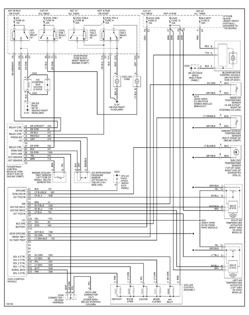
Use the schematic I posted in the thread quicksilver linked to above to test the circuit. If you get all the way to the board and don't find anything crossed I'd say you've found your issue.
Definitely sounds like you might have soldered something together that you shouldn't have; I'm not really familiar with the layout of that board.
Use the schematic I posted in the thread quicksilver linked to above to test the circuit. If you get all the way to the board and don't find anything crossed I'd say you've found your issue.
Tech Contributor
Joined: Aug 2008
Posts: 2,902
Likes: 21
From: Oak Hill Virginia
Tech Contributor


Joined: Jan 2007
Posts: 19,465
Likes: 1,166
From: Dyer, IN

Racer
Joined: Mar 2011
Posts: 377
Likes: 3
From: Cudahy WI
You burned out a trace or transistor on the rear board of the HVAC unit.
Don't feel bad, I did the same thing.
Go over your front board (with the lights) with a fine toothed comb looking for any shorts, bridges, etc, then either replace your HVAC, or do as I did and just replace the rear board with one from a damaged HVAC purchased from one of the friendly members of this board. I burned out an 02 HVAC and replaced the rear board with one from an 01 and it works perfectly now.
Thread Starter
Advanced
Joined: Aug 2004
Posts: 85
Likes: 0
From: Arlington TX
I went over all my work and cleaned everything, yet the lights still stay on. There are a couple of spots on the PCB trace that look a little suspicious, but I'm not sure.
I checked the voltage at various spots, and I have about 11.9V coming into the board at pin C12 from the harness. I turned the ignition on, and I do not get a voltage reading at pin C5, which is labeled as "IGN" on the schematic, which goes to the fuse block at the passenger side (fuse 51). I assume this is for "ignition" and should shut the unit off when the ignition is turned off, with the delay of course. If the unit is connected at pin C12 with a "hot at all times" connection, how does the unit get into sleep mode then? It seems the lights should not be connected here (not sure exactly what is...memory?) and should be connected at the pin C12, which should go to some relay for the delay.
I also checked voltage at the two transistors on the rear board and one was 11.9V and the other was around 2.3V. I'm not sure what this means, or what even their function is (driver and passenger temp controls?)...I think if I had the full schematic for the front and rear boards, I could fix this.
Another problem is trying to trace the PCB. A lot of the trace goes under components and you can't tell where it's going.
Any further help is appreciated...especially a full schematic for the unit. I fear I will soon be buying another one.
Corvette Stories
The Best of Corvette for Corvette Enthusiasts

Top 10 Most Expensive Corvettes Ever Sold on Bring A Trailer
Brett Foote
10 Things Every Corvette Owner Needs (2026 Edition)
Michael S. Palmer
8 Most "Only Corvette Owners Understand" Quirks and Problems
Pouria Savadkouei
10 Reasons the C6 Z06 is Still A Performance Benchmark After 20 Years
Joe Kucinski
How Much Horsepower Every Corvette Engine "LOST" in 1972
Joe Kucinski
Top 10 DOs and DON'Ts for Protecting Your Convertible Top!
Michael S. Palmer
Top 10 Most Explosive Corvettes Ever Made: Power-to-Weight Ratio Ranked!
Joe Kucinski
150 hp to 1,250 hp: Every Corvette Generation Compared by the Specs That Matter
Joe Kucinski
8 Coolest Corvette Pace Cars (and Replicas) of All Time
Verdad GallardoTech Contributor
Joined: Jan 2007
Posts: 19,465
Likes: 1,166
From: Dyer, IN