


Help ! C5 Speedometer not registering MPH !

Thread Starter
Intermediate


Joined: Feb 2013
Posts: 34
Likes: 1
From: Norwich Norfolk
I'm inspecting the red PCM connector now, the outside of the connector is contaminated with battery residue, the wiring is good, but on inspection with a lamp and a magnifing glass ( upside down under the car ) I think the pins are lightly coated in the same residue.( a light powder)
I'm just heading out to buy some electrical connector cleaner that will evaporate off that I can apply with a toothbrush.
Then I'll bolt it back together and try again.
If that doesn't work, it's into the IPC connector.
Fast forward an hour and a half = cleaned the plug and the PCM pins bolted back together, short drive, no joy !
I will chase the pin 50 wire to the connector under the bonnet and check continuity, if that's good then it's dash out time !

Le Mans Master

Joined: Mar 2011
Posts: 6,835
Likes: 302
From: Columbia SC
Before you go into the IPC connector, make sure you also clean the same location on the PCM. If you had an issue with the connector, the same issue is probably on the PCM too.
Sorry, reread your post, looks like you cleaned everything.
Sorry, reread your post, looks like you cleaned everything.
Last edited by dadaroo; Feb 26, 2013 at 09:26 AM. Reason: Clarify
Thread Starter
Intermediate
Joined: Feb 2013
Posts: 34
Likes: 1
From: Norwich Norfolk
He's coming over in the morning so I'll keep you posted on what transpires !
Fingers crossed and thanks for all your help, it's been invaluable!
Le Mans Master
Joined: Mar 2011
Posts: 6,835
Likes: 302
From: Columbia SC
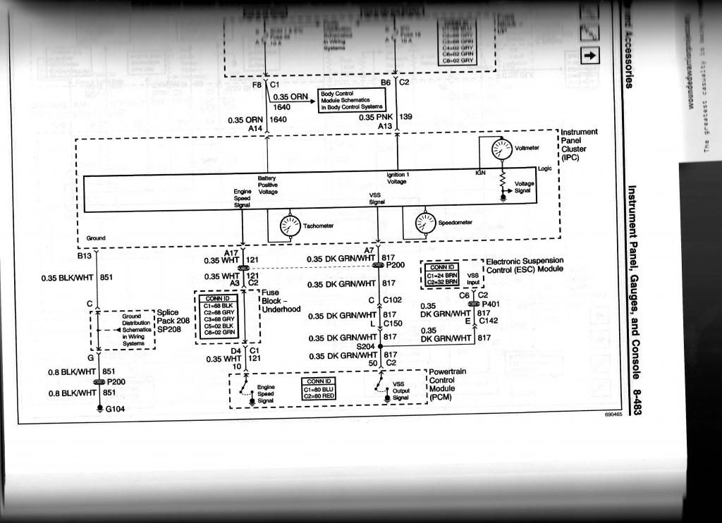
I looked again at the schematic wiring. There are 2 connectors between the PCM and the IPC that carry the signal. The first one in C150 (round) and then C102 (rectangular). Then the wiring passes through the firewall and directly to the IPC. The wire color does not change. Not sure how difficult to locate. You might try checking these first. Anyway if you need the pin locations for these I can scan and send later today. I sure hope it is not the PCM, sure wish your replacement had worked. Before you actually tear into the dash, you might want to see if the vendor can get you another PCM to try. Here is what the schematic shows.
Le Mans Master
Joined: Mar 2011
Posts: 6,835
Likes: 302
From: Columbia SC
Just thought of something when looking at this schematic. To the right do you see the PCM also feeds VSS to the ESC module. I don't know if you have ESC or not, if you do and it is not throwing a code then it would make sense that the PCM is outputting the VSS signal from connector C2. S204 is a splice where this ties into the output wire from pin 50. Sorry did not think of this sooner.
Le Mans Master
Joined: Mar 2011
Posts: 6,835
Likes: 302
From: Columbia SC
Hey, I think the code you are getting on RTD may be coming from the ESC module meaning the VSS putput from the PCM is bad. If you have cleaned the connection well, I think you need to work to get a repalcement PCM that can talk to the BCM before you go into the dash and IPC. That is what I would do next. What say?
Thread Starter
Intermediate
Joined: Feb 2013
Posts: 34
Likes: 1
From: Norwich Norfolk
Hey, I think the code you are getting on RTD may be coming from the ESC module meaning the VSS putput from the PCM is bad. If you have cleaned the connection well, I think you need to work to get a repalcement PCM that can talk to the BCM before you go into the dash and IPC. That is what I would do next. What say?
I hope the PCM problem isn't that bad, as the only GM approved Corvette dealer I can find in the UK with the software is in Manchester (250 miles) and they can only do it with the car present.
I wonder if I could get a custom flash from a specialist in the UK.
That's another job for tomorrow ( and Google tonight !)
Corvette Stories
The Best of Corvette for Corvette Enthusiasts

Top 10 Most Explosive Corvettes Ever Made: Power-to-Weight Ratio Ranked!
Joe Kucinski
150 hp to 1,250 hp: Every Corvette Generation Compared by the Specs That Matter
Joe Kucinski
8 Coolest Corvette Pace Cars (and Replicas) of All Time
Verdad Gallardo
Top 10 Corvette Engines RANKED by Peak Torque (70+ Years of Muscle!)
Joe Kucinski
Corvette ZR1X Will Be Pacing the Indy 500, And Could Probably Race, Too!
Verdad Gallardo
Top 10 Corvettes Coming to Mecum Indy 2026!
Brett Foote
Top 10 C9 Corvette MUST-HAVES to Fix These C8 Generation Flaws!
Michael S. Palmer
10 Revolutionary 'Corvette Firsts' Most People Don't Know
Joe Kucinski
5 Reasons to Upgrade to an LS6-Powered Corvette; 5 Reasons to Stay LT2
Michael S. PalmerRace Director


Joined: Apr 2007
Posts: 11,150
Likes: 890
From: South Western Ontario
Trace the wire first. Pull off the tape and check out the physical wire from the PCM connector to connector C150. It should splice in there somewhere and you'll find the split where it heads off to the cluster and the ESC/RTD module.
When looking at wires like this they can rot inside the insulation. You need to pull on any wire length in question. If the wire can be stretched then it's broken inside. Open the back side of the PCM connector and check the wiring inside there too.
If the wire physically checks out, the next thing is disconnect C150 and disconnect the ESC connector off the ESC/RTD module in the storage compartment and ohm test the PCM side of the wire to ground to see if it has a short. Ohm test the wire between the PCM connector and the C150 connector. You could also grab enough test wire to ohm test the wire from the PCM to the ESC/RTD module to make sure it's connected.
If the wire looks and ohms OK then see if you can de-pin the wire from C150, tape it up and take the car for a drive. If the RTD code clears then it's in the instrument panel or the wire going to it. If it doesn't clear then it's likely the PCM.
If you had a frequency generator I'd inject a frequency into the wire at about 10V and 2000Hz and see if the speedo reads - My guess would be that you'd see 60mph at 2000Hz. I doubt you have such a thing though.
I believe C150 and C102 will be connectors down by the battery or at least in that area of the engine compartment. I also believe the wiring to the ESC module runs down along the torque tube and then goes through the body into the storage compartment. I haven't actually seen the ESC module wiring but that routing would make sense. So, pull the battery and battery tray and the surround around the battery and you should have access to the wiring you need.
A note on splicing. The car audio guys love the quick crimp connectors. Don't use them in the engine compartment. Twist splice, solder and double wall heatshrink is the way to go. If not that, then there are weatherproof splice kits that consist of 3 or 4 pieces where you put an end over each wire and then screw it into a center piece. Just remember, anything cheap and quick will likely fail again.
Le Mans Master
Joined: Mar 2011
Posts: 6,835
Likes: 302
From: Columbia SC
I agree with what lionelhutz says for checking the wiring. Based on the battery corrosion, my bet is on a bad PCM or C2 connector problem. Keep us posted and we will solve this thing. Have you talked with the vendor about a replacement PCM for the one that will not work with your BCM? Ask if they actually had the ability to test the PCM for full function before reflashing for your VIN?
Thread Starter
Intermediate
Joined: Feb 2013
Posts: 34
Likes: 1
From: Norwich Norfolk
One question I have is ; where does the PCM get the VSS signal from initially ? directly from the VSS or inderectly ? and does it go INTO the other PCM connector as I haven't given that side such a thorough clean .
Le Mans Master
Joined: Mar 2011
Posts: 6,835
Likes: 302
From: Columbia SC
The VSS signal goes directly into the PCM, I have attached the schematic. We "know" that is working since the PCM sends this signal (via serial bus) to the BCM which then sends it (via serial bus) to the DIC for cruise control mph display. The serial bus is just a one wire from/to each module so they can communicate/transfer information.The design does not give a code for loss of the speed signal to the IPC like it does for ESC/RTD since the ESC has a module that can commnicate back via serial bus it's trouble code(s). VSS input to the PCM is also via connector C2. Pin 20 Purple wire is "VSS Reference Low" and Pin 21 Yellow wire is "VSS Signal".
Assuming the cause of no speed display at the IPC and the code from ESC/RTD are caused by the same thing (which at this point is a rational assumption) you have a problem at the splice affecting both circuits (I really doubt this), the wire from the splice to C2 is bad (I doubt) or the C2 pin 50 output is bad due to the acid (more likely), or the PCM is bad due to acid or just failed (this is what I put my money on).
Let me know if you need some more info.Hopefully we will not need an Exorcist.
Last edited by dadaroo; Feb 27, 2013 at 09:49 AM. Reason: Add schematic
Thread Starter
Intermediate
Joined: Feb 2013
Posts: 34
Likes: 1
From: Norwich Norfolk
My Auto electrician has diagnosed it as a bad PCM !!
I am in contact with a company in the UK who are EFIlive specialists, they can reflash the new PCM and get past the VATS problem.
I will go down that route and report back !
Thanks again for all your time and enthusiasm helping me with this problem, you have made me feel I'm not alone !!
I am in contact with a company in the UK who are EFIlive specialists, they can reflash the new PCM and get past the VATS problem.
I will go down that route and report back !
Thanks again for all your time and enthusiasm helping me with this problem, you have made me feel I'm not alone !!
Le Mans Master
Joined: Mar 2011
Posts: 6,835
Likes: 302
From: Columbia SC
I am glad to hear that. I have used this to learn a lot myself which I shall put to good use in the future (hopefully on other's cars). The C5 is my first "toy" with electronics. All my other cars are butt simple to work on since they are all 40-45 years old. I would like to see you say "joy" instead of "no joy" in your final post.
Le Mans Master
Joined: Mar 2011
Posts: 6,835
Likes: 302
From: Columbia SC
PS: I would like to thank Lionelhutz for his valuable input. This morning when I was going over the posts to see if I missed anything I saw in his post 15 the link between the ESC and the IPC, but I was too ignorant on the design and wiring to realize the connection at that time. Also his input on the serial data bus helped to explain why you could see mph on the DIC. This morning I spent a good deal of time learning how this system worked. I had assumed the wiring looked like the inside of my computer, not just a single wire to/from each component. Apparently this old dog can learn some new tricks.
Thread Starter
Intermediate
Joined: Feb 2013
Posts: 34
Likes: 1
From: Norwich Norfolk
PS: I would like to thank Lionelhutz for his valuable input. This morning when I was going over the posts to see if I missed anything I saw in his post 15 the link between the ESC and the IPC, but I was too ignorant on the design and wiring to realize the connection at that time. Also his input on the serial data bus helped to explain why you could see mph on the DIC. This morning I spent a good deal of time learning how this system worked. I had assumed the wiring looked like the inside of my computer, not just a single wire to/from each component. Apparently this old dog can learn some new tricks.

Race Director
Joined: Apr 2007
Posts: 11,150
Likes: 890
From: South Western Ontario
Good to hear that you have confirmed it's the PCM.
I hope turning off the VATS will let the car run for you.
The relearn procedure should have worked. I did some searching here and didn't find anyone having trouble with it. What condition if your battery in? A low battery might cause it to fail. Maybe put the car on a charger for a few hours and then try it again with the charger connected.
Thread Starter
Intermediate
Joined: Feb 2013
Posts: 34
Likes: 1
From: Norwich Norfolk
The battery is new, I kept it on charge throughout the attempted relearns.
The guy I'm taking it to can turn off the VATS and perform anything that's needed on the new PCM so hopefully it will enable the speedo to work !
I hope so, it's a 250 mile round trip on Saturday, I will post the results on here, thank you for your help.
The guy I'm taking it to can turn off the VATS and perform anything that's needed on the new PCM so hopefully it will enable the speedo to work !
I hope so, it's a 250 mile round trip on Saturday, I will post the results on here, thank you for your help.
Team Owner


Joined: May 2003
Posts: 23,480
Likes: 9
From: East Meadow NY
St. Jude Donor '12
The battery is new, I kept it on charge throughout the attempted relearns.
The guy I'm taking it to can turn off the VATS and perform anything that's needed on the new PCM so hopefully it will enable the speedo to work !
I hope so, it's a 250 mile round trip on Saturday, I will post the results on here, thank you for your help.
The guy I'm taking it to can turn off the VATS and perform anything that's needed on the new PCM so hopefully it will enable the speedo to work !
I hope so, it's a 250 mile round trip on Saturday, I will post the results on here, thank you for your help.
Thread Starter
Intermediate
Joined: Feb 2013
Posts: 34
Likes: 1
From: Norwich Norfolk
If this turns out to be a cheap fix, I will take great pleasure in letting them know !
Ironically, the guy I'm taking it to is less than 15 miles from the person I bought it from !!