


Balancer bolt

Thread Starter
Racer


Joined: Oct 2010
Posts: 450
Likes: 18
From: NORTHPORT NY
I'm in the process of changing my hb. After reading threads I decided to. Go with the guys who use the arp bolt.... My question is do I still have to use the old bolt to 240 lbs or do I just go to the 235 lbs with the arp bolt.
Team Owner


Joined: Sep 2001
Posts: 23,283
Likes: 906
From: Lake Elsinore, CA
Do not use the old bolt to install the pulley - use the correct tool. Either buy or make the correct setup with threaded rod. Using the old bolt only allows a minimum of threads to start the press-fit of the pulley and can strip the crank snout threads. With threaded rod, you will have lots of threads anchoring the rod, ensuring you will not damage the crank. Install the HB to the factory spec'ed distance and then torque the ARP bolt to 235 ft. lb.
I think this simple procedure is one of the most misunderstood and improperly applied here. Here is the procedure from the Service Manual, assuming you are using a stock TTY bolt (you can substitute the ARP bolt in where they do the final new bolt ). Steps 5 & 6 are for getting the final distance of the HB relative to the crank snout - not to press the HB onto the snout.
4] Use the J 41665 in order to install the crankshaft balancer.
5] Install the used crankshaft balancer bolt. Tighten the used crankshaft balancer bolt to 330 N�m (240 lb ft).
6] Remove the used crankshaft balancer bolt.
Important
The nose of the crankshaft should be recessed 2.40-4.48 mm (0.094-0.176 in) into the balancer bore.
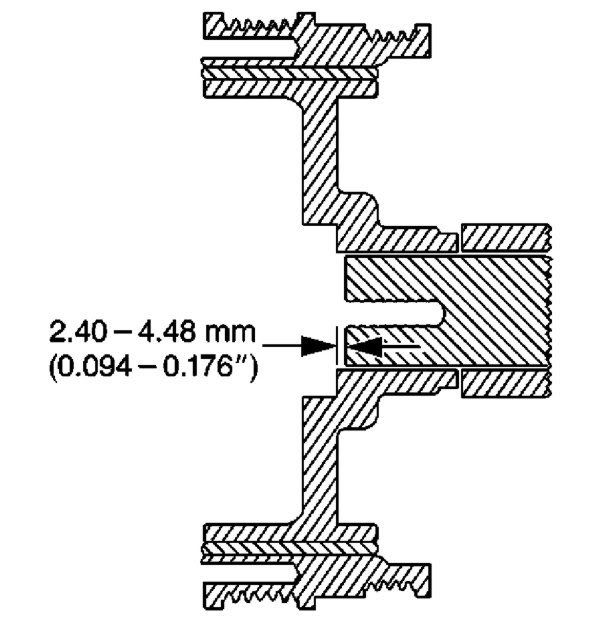
7] Measure for a correctly installer balancer. If the balancer is not installed to the proper dimensions, install the J 41665 and repeat the installation procedure.
8] Install the NEW crankshaft balancer bolt. Tighten
a. Tighten the new crankshaft balancer bolt a first pass to 50 N�m (37 lb ft).
b. Tighten the new crankshaft balancer bolt a second pass to 140 degrees using the J 36660-A.
The J 41665 is the GM balancer installation tool. There are several threads that instruct in the fabrication of a balancer installation tool using threaded rod, nuts and washers to substitue for the J 36660-A. I made one several years ago that worked great. Also it is a good idea to pin the pulley to the crank to prevent spinning problems in the future.
Here's a pic of one type of pinning tool.
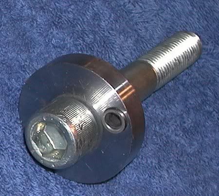
A pic of a pinned pulley - you can see the 1/4" dowel pin at 12 o'clock near the center.

A shot of my underdrive pulley. Note the two marks at 0 and 140 degrees I made to indicate when I had torqued the pulley bolt sufficiently.

I think this simple procedure is one of the most misunderstood and improperly applied here. Here is the procedure from the Service Manual, assuming you are using a stock TTY bolt (you can substitute the ARP bolt in where they do the final new bolt ). Steps 5 & 6 are for getting the final distance of the HB relative to the crank snout - not to press the HB onto the snout.
4] Use the J 41665 in order to install the crankshaft balancer.
- Assemble the threaded rod, nut, washer and installer. Insert the smaller end of the installer into the front of the balancer.
- Use a wrench and hold the hex end of the threaded rod.
- Use a second wrench and rotate the installation tool nut clockwise until the balancer is started onto the crankshaft.
- Remove the tool and reverse the installation tool. Position the larger end of the installer against the front of the balancer.
- Use a wrench and hold the hex end of the threaded rod.
- Use a second wrench and rotate the installation tool nut clockwise until the balancer is installer onto the crankshaft.
- Remove the balancer installation tool.
5] Install the used crankshaft balancer bolt. Tighten the used crankshaft balancer bolt to 330 N�m (240 lb ft).
6] Remove the used crankshaft balancer bolt.
Important
The nose of the crankshaft should be recessed 2.40-4.48 mm (0.094-0.176 in) into the balancer bore.
7] Measure for a correctly installer balancer. If the balancer is not installed to the proper dimensions, install the J 41665 and repeat the installation procedure.
8] Install the NEW crankshaft balancer bolt. Tighten
a. Tighten the new crankshaft balancer bolt a first pass to 50 N�m (37 lb ft).
b. Tighten the new crankshaft balancer bolt a second pass to 140 degrees using the J 36660-A.
The J 41665 is the GM balancer installation tool. There are several threads that instruct in the fabrication of a balancer installation tool using threaded rod, nuts and washers to substitue for the J 36660-A. I made one several years ago that worked great. Also it is a good idea to pin the pulley to the crank to prevent spinning problems in the future.
Here's a pic of one type of pinning tool.
A pic of a pinned pulley - you can see the 1/4" dowel pin at 12 o'clock near the center.
A shot of my underdrive pulley. Note the two marks at 0 and 140 degrees I made to indicate when I had torqued the pulley bolt sufficiently.
Last edited by Patches; Mar 31, 2014 at 05:28 PM.
Thread Starter
Racer
Joined: Oct 2010
Posts: 450
Likes: 18
From: NORTHPORT NY
Patches thanks for the help.....I do have the tool to press the new hb on. I was confused as too the need to use the old bolt then the new bolt... I was thinking that you could just put the arp bolt in and not need to use the old bolt first.
Team Owner
Joined: Sep 2001
Posts: 23,283
Likes: 906
From: Lake Elsinore, CA
That's what I do - press the pulley on to the proper distance spec and then install the ARP bolt.
Thread Starter
Racer
Joined: Oct 2010
Posts: 450
Likes: 18
From: NORTHPORT NY
Thanks again ....the job was easier than I thought I was thinking the steering rack was gonna be a nightmare. A member said use a 18mm crowfoot flair nut and it was a snap I then dropped the cradle and it came out the drivers side. I got the old bolt out with heat and my impact gun. So far so good. Thanks again. Should I use lock tite ?
Corvette Stories
The Best of Corvette for Corvette Enthusiasts

Top 10 Most Explosive Corvettes Ever Made: Power-to-Weight Ratio Ranked!
Joe Kucinski
150 hp to 1,250 hp: Every Corvette Generation Compared by the Specs That Matter
Joe Kucinski
8 Coolest Corvette Pace Cars (and Replicas) of All Time
Verdad Gallardo
Top 10 Corvette Engines RANKED by Peak Torque (70+ Years of Muscle!)
Joe Kucinski
Corvette ZR1X Will Be Pacing the Indy 500, And Could Probably Race, Too!
Verdad Gallardo
Top 10 Corvettes Coming to Mecum Indy 2026!
Brett Foote
Top 10 C9 Corvette MUST-HAVES to Fix These C8 Generation Flaws!
Michael S. Palmer
10 Revolutionary 'Corvette Firsts' Most People Don't Know
Joe Kucinski
5 Reasons to Upgrade to an LS6-Powered Corvette; 5 Reasons to Stay LT2
Michael S. PalmerTeam Owner


Joined: May 2001
Posts: 87,323
Likes: 1,587
From: Western NY
Thanks again ....the job was easier than I thought I was thinking the steering rack was gonna be a nightmare. A member said use a 18mm crowfoot flair nut and it was a snap I then dropped the cradle and it came out the drivers side. I got the old bolt out with heat and my impact gun. So far so good. Thanks again. Should I use lock tite ?
Melting Slicks

Joined: Nov 2008
Posts: 2,938
Likes: 65
From: Rochester Hills MI
You can certainly use the arp bolt to the proper distance and reuse it to apply the final torque. I would do more research on the torque value. You will see a lot of different answers on this and may depend on what type of lubricant you use (5w30, arp moly lube, red loctite). I would certainly suggest using the arp moly lube and torquing to 235ft lbs but you can use your own judgement. I think realistically you could torque to 190ft lbs as long as the crank is pinned.