
Working on some hybrid cutouts for my FRC
 04-08-2016, 03:52 PM
#21
2nd Gear


Member Since: Apr 2016
Posts: 2
Likes: 0
Received 0 Likes
on
0 Posts
I'm build an exhaust using vacuum cutouts as well, however I am using the normally open type to build an active exhaust. I'm not building this for a corvette, actually a miata, so some of these assumptions may be wrong. But I figure we can share ideas.
For vacuum, I need two types: constant and variable. For constant, I plan to get that by tapping into the brake booster vacuum line after the check valve. For variable, that will come from the intake manifold vacuum line.
nsogiba, sounds like you just need a constant source and open/atmospheric. So you can use the brake booster line for the constant source.
For solenoid, I am planning to use a MAC 35A-AAA-DDBA-1BA 3 way solenoid. This will allow me to choose from two types of sources and switch between the two.
I plan to hook up the normally open port to the manifold vacuum line, this will allow the the valve to open as throttle opens and vacuum drops. The normally closed port will get the brake booster vacuum, so I can keep the valve closed all the time if need be.
nsogiba, here you can leave the normally open port alone and attached the brake booster vacuum to the normally closed port.
Last edited by mx5dude; 04-08-2016 at 03:53 PM.
 04-08-2016, 04:00 PM
#22
Drifting

Thread Starter

I don't think I can just tap into the brake booster. Upon acceleration my vacuum will go away and the cutouts will shut. So it'd be the opposite of the desired effect.
edit: you mean as a general source - you didn't mention until later in the post the use of the solenoid. Makes sense now. I still plan on using the Ford vacuum solenoid mentioned in previous posts for simplicity.
edit: you mean as a general source - you didn't mention until later in the post the use of the solenoid. Makes sense now. I still plan on using the Ford vacuum solenoid mentioned in previous posts for simplicity.
Last edited by nsogiba; 04-08-2016 at 04:02 PM.
04-08-2016, 04:15 PM
#23
2nd Gear
Member Since: Apr 2016
Posts: 2
Likes: 0
Received 0 Likes
on
0 Posts
Ah, you are correct. The check valve is on the C5’s brake booster, where on the miata the check valve is inside the vacuum line that runs to the brake booster.
Perhaps you can pull the brake booster line, install a check valve, tap a line, then reconnect to the brake booster’s check valve? The brake booster needs constant vacuum engine on or off, so I don’t think an secondary check valve would cause problems.
Perhaps you can pull the brake booster line, install a check valve, tap a line, then reconnect to the brake booster’s check valve? The brake booster needs constant vacuum engine on or off, so I don’t think an secondary check valve would cause problems.
04-08-2016, 04:18 PM
#24
Drifting
Thread Starter
I am using a vacuum canister that has an internal check valve built in that will act as a reservoir for the cutouts so that they will stay open even when the engine is under high load (low vacuum)
04-08-2016, 06:52 PM
#25

sorry i was so excited to see someone with the same idea i didnt read your whole post i missed the normally closed, i chose the normally open
, did you find a three way solenoid yet?
i am curious to see how you set this up. i almost went this route but wanted mine to gradually open with more throttle.
, did you find a three way solenoid yet?
i am curious to see how you set this up. i almost went this route but wanted mine to gradually open with more throttle.
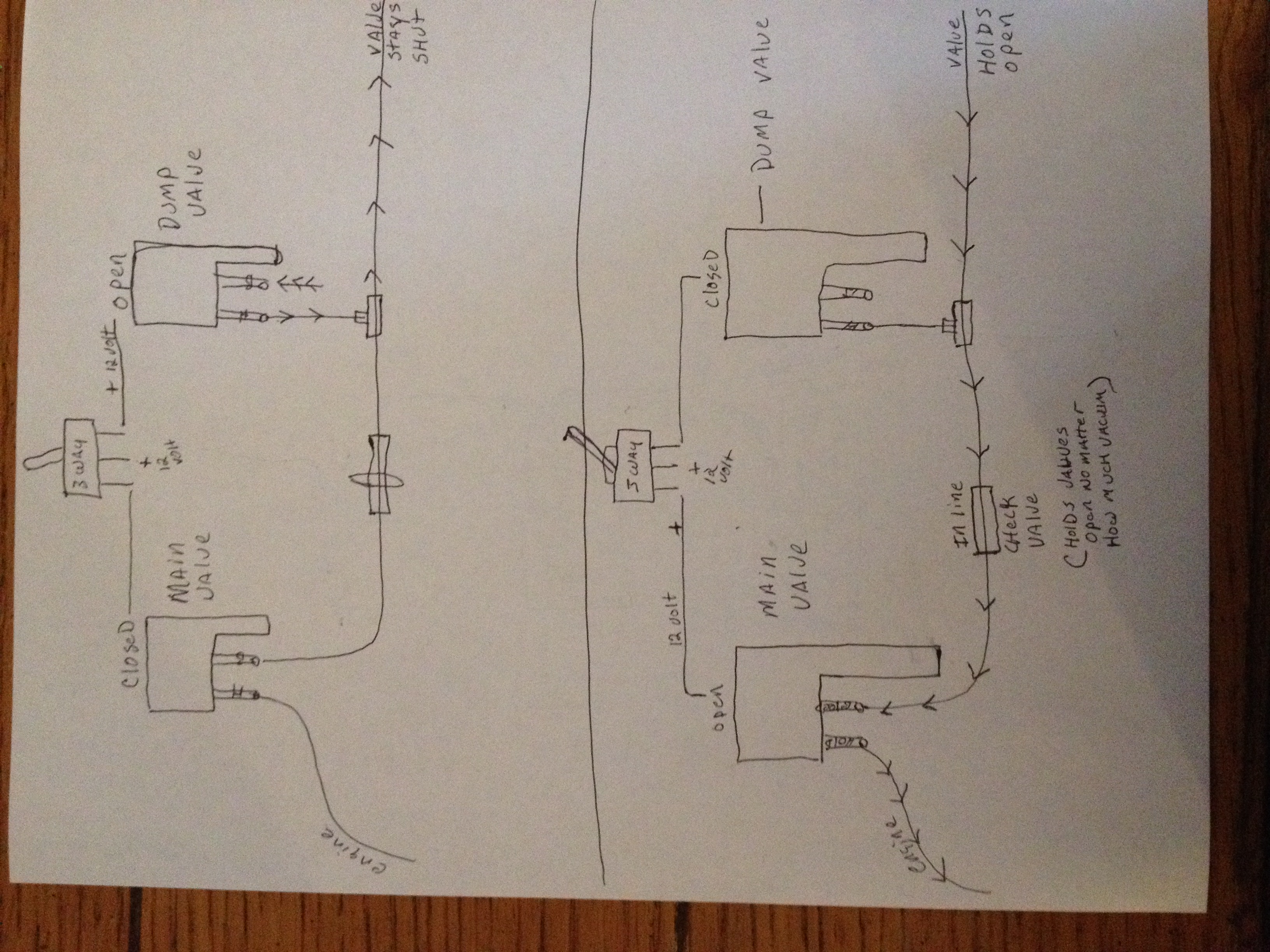 not sure if this will help but this is the routing schematic from my system in reverse[ for normally closed] using the gm style solenoids
04-08-2016, 10:31 PM
not sure if this will help but this is the routing schematic from my system in reverse[ for normally closed] using the gm style solenoids
04-08-2016, 10:31 PM
#27
Administrator


Member Since: Mar 2001
Location: In a parallel universe. Currently own 2014 Stingray Coupe.
Posts: 343,001
Received 19,301 Likes
on
13,974 Posts
C7 of the Year - Modified Finalist 2021
MO Events Coordinator
St. Jude Co-Organizer
St. Jude Donor '03-'04-'05-'06-'07-'08-'09-'10-'11-'12-'13-'14-'15-'16-'17-'18-'19-
'20-'21-'22-'23-'24
NCM Sinkhole Donor
CI 5, 8 & 11 Veteran


Subscribed - great work so far and looking forward to seeing how this plays out.
04-12-2016, 10:02 PM
#28
Drifting
Thread Starter
Very cool. I love to see one-off, quality mods like this. It's nice to see someone make it their own.
I worked for BMW when they were using the vacuum actuators on everything. Much like their turbo wastegates, their exhaust actuators would rattle their gibblets off. If you ever hear a 335i on cold start, usually one or the other is rattling. Your parts look to be of much better quality though.
Looking forward to seeing how this turns out!
Initial impressions - the cutouts do a great job of sealing the exhaust noise when closed. I laid underneath the car while it warmed up for a good 10 minutes, feeling with my hand for any leaks or telltale "puffing" in and around the valve itself. Nothing at all. There was the occasional drop of condensation that came out of the closed butterfly, but this is to be expected and went away as the system warmed up and expanded.
The one downside that I did encounter (and it's why I quoted the above message) is that the closed valves do have a slight rattle around the 1100 rpm mark, on cold start. It's very faint but when you listen hard from outside the car, it's there. I am thinking about slightly modifing the bellcrank on the outside so that the hardstop opens the valve by just a hair more - to prevent contact and take up any slop in the linkage. I was not able to verify if it was the butterfly valve rattling on the housing, or the linkage itself (ball end/socket). Will find out and report back.
Still need to figure out the control system - but I did open the valves by hand while laying under the car when it was running on the lift - makes some nice angry sounds at idle


Stay tuned, more to come next week
Last edited by nsogiba; 04-13-2016 at 11:13 AM.
04-13-2016, 07:04 PM
#29
mine rattled a little also, i put couple turns on the threaded rod to put a little more pressure on the control arm and that seemed to correct it, although mine has vacuum holding them closed so it keeps the a little tighter.
04-14-2016, 12:28 AM
#30
Race Director

Member Since: Apr 2007
Location: South Western Ontario
Posts: 11,061
Received 845 Likes
on
721 Posts

From your picture, it appears the vacuum canister is the "spring" that holds them closed. You will never take up the slop in the linkage by shortening the pull rod. So, like carluver I would suggest trying a little longer on the pull rod so the canister is pushing them closed a little harder. The only other option is shorter so the butterfly is slightly open but that could create an exhaust leak sound.
05-19-2016, 09:14 AM
#31
Drifting
Thread Starter
I have been tinkering with this project on and off the last couple weeks. Car needed tires, front bumper needed replacing due to a coworker running into me, etc etc.
I had poor results with the Ford solenoids that I pulled from the junkyard - I bought 3 thinking at least one would be bad due to old age and use, and sure enough 2 out of 3 leaked when subjected to vacuum. The remaining one worked marginally, but I wasn't happy with how it held vacuum. (insert typical Ford joke here). The Ford stuff was also normally open, which would have caused a vacuum leak when power was not applied. I had trouble locating working diagrams for how these solenoids work (normally open, normally closed, which port vents, etc), so I bit the bullet and bought a GM solenoid on Amazon and crossed my fingers.
I rigged up a test setup with a small 12V power supply (again from amazon), and applied suction to the 2 ports until I figured out which one was supposed to be the "source vacuum" port. Success! With the 12V off, the solenoid was normally closed, which would allow the engine to run normally with no vacuum leak. 12V on, and the valve opened, allowing vacuum to be sent to the line that connects to the cutouts. When 12V was shut off again, the valve closed, removing vacuum from the cutout lines, and the downstream lines vented the vacuum, which will allow the spring pressure in the cutouts to snap them shut.
All that's left is to:
mount the vacuum reservoir and solenoid (thinking under the car, up by the fuel filter)
mount the switch (need to remove console to do this as I'm putting it where the ashtray is). Might also install my C6 shifter while I'm at it, as well as add another washer for the anti-venom mod
Wire in my 12V source to the switch, run the wiring to the solenoid under the car
tap into brake booster line for vacuum source.
Does anyone know what the size of the Brake Booster vacuum line is, so I can buy a Tee?
05-27-2016, 08:33 AM
#32
Drifting
Thread Starter
Well, 2 steps forward, 1 step back. I plumbed the entire vacuum system for the cutouts - sourcing from the booster line, running along the firewall, through the passenger firewall behind the battery, and through the passenger compartment to the trunk. I mounted the vacuum canister and solenoid in the cargo well next to the CD Changer. Vacuum output from the solenoid ran through a small hole in the cargo well, up and around the diff, and then tee'd to each cutout. Tested it with the engine running and 12V from a wall adapter. Both cutouts open all the way - I was concerned that the vacuum wouldn't be strong enough to overcome the spring pressure of both units, but it works well.
Time to put it all back together and source power from the car - there is an unused harness connector in the passenger footwell that provides a ground, switched power, and constant power - so I wired my power and ground to the switched wire and ran back to my pushbutton switch in the ashtray. Good tips here on where to find it:
http://frankhunt.com/FRANK/hobbies/c...e_install.html
Before putting the dash back together, I yet again tested it with the engine running, now pulling power from that harness inside the car - still worked great.
Put shifter surround trim back in, tested it - blew fuse. Replace fuse, try again, SNAP, blew fuse. Remove console, replace fuse, try again, works. Put shifter surround back in, SNAP, blew fuse. I think I am pinching a wire somewhere. It's a 20A circuit, so I can't see that little vacuum solenoid pulling more current than that, especially since that fuse is not shared with any other circuits. So close to being done! Unfortunately I won't be able to work on the car much this weekend so it will have to sit in the back of my mind and bother me until I can spend some time on it.
On a positive note I did pick up my S2000 seats from the shipping terminal and they look great. Leather needs a quick cleanup and maybe some shoe polish on the bolsters but otherwise like new.
05-31-2016, 09:35 AM
#33
Drifting
Thread Starter
Finally got my cutout setup finished up. Quick video of a rigged setup, using vacuum from the engine and power from a 12V adapter plugged into the wall. Just testing operation here.
I ran the wiring inside the car and tapped into the fused switched power and kept blowing fuses - took the console back apart on Memorial Day and found 2 spots where the console had pinched the power wire, which broke the insulation and grounded it to the metal chassis tunnel. Replaced that section of wire, and got the whole interior finally back together. Test drive went great, works exactly as expected, the nice part is how quickly the cutouts close when you want them off. The spring snaps them shut in about half a second. In car videos to come.
I ran the wiring inside the car and tapped into the fused switched power and kept blowing fuses - took the console back apart on Memorial Day and found 2 spots where the console had pinched the power wire, which broke the insulation and grounded it to the metal chassis tunnel. Replaced that section of wire, and got the whole interior finally back together. Test drive went great, works exactly as expected, the nice part is how quickly the cutouts close when you want them off. The spring snaps them shut in about half a second. In car videos to come.
Last edited by nsogiba; 05-31-2016 at 09:35 AM.

 06-02-2016, 08:12 AM
#36
Drifting
Thread Starter
I burned about $100 trying out various vacuum solenoids until I found one that worked.
Another $50 in vacuum fittings, tees, and hoses finding the right combination
Wiring was free, left over from previous projects. Switch was $10
Welding in the cutouts, with saddle tee material, v-bands for serviceability, $300 I think
Cutouts themselves, $350 I think.
I am debating putting this together as a package and selling for folks who want a turn-key solution without having to engineer anything.
Last edited by nsogiba; 06-02-2016 at 08:13 AM.
08-01-2017, 01:30 PM
#37
Drifting
Thread Starter
I'm surprised someone hasn't tried a bypass setup that uses one of the factory tailpipes as a bypassed exhaust and the other as a muffled one. As on a Z06, the muffler is one in and one out with the tailpipes split off the single outlet. Why not try removing the innermost exhaust outlet, configure the bypass to tap off the midpipe just upstream of the muffler and then route out where the original inner tailpipe exit was? It would look factory from the back and safely allow exhaust out the rear. That would look good and sound good without dumping under the car.
The system itself is functioning flawlessly and has held up to several track days in 90F heat without any adverse effects on the car.
The downside is that the drone of the cutouts, while cruising, is unbearable. It hasn't gotten any worse since I installed them, I guess I've just gotten less tolerant of it.
So, I'm revising my setup in the way that CaseyJones describes above - essentially a "bypass mod on demand". A 3" pipe (with a vacuum cutout inline) will connect the Muffler Inlet to the "inner outlets, while the "outer outlets" will still remain functional as dumping the muffled exhaust. Obviously I'm doing this to a stainless base model axle back, not the Z06 Ti Mufflers (I sold those knowing I couldn't weld on them).
I am partially doing this to eliminate/reduce the drone inside the car, but also in preparation for the installation of the N2MB WOT BOX I have sitting in my garage. I don't want those high pressure flames between upshifts dumping underneath the car/next to the transmission. Much prefer them to go out the back where they can be enjoyed
Here's the design that I'm after (not my pics!!)

I will post pictures of my progress as I go.
The following users liked this post:
VFR RC46 (10-12-2018)
 04-23-2018, 11:09 PM
#39
Intermediate

Member Since: May 2017
Location: Pleasant Prairie WI
Posts: 35
Received 0 Likes
on
0 Posts
Did anyone ever put just one cut out on the super short horizontal cross pipe of the stock H pipe? I like the vacuum actuators shown in this thread and think I could package one in there just to make the exhaust louder not to make it flow better. I have not seen this done but it look pretty simple to do. Just not sure how much louder it would be. I have see in the forums that the holes need opened up at the ends of the cross pipe but I could do this while I'm in there. I already did the tailpipe partial bypass on the titanium section of exhaust and this sounds good but for track days it would be nice to be louder. Thanks in advance for any information on this modification.
04-24-2018, 08:56 AM
#40
Drifting
Thread Starter
I didn't have a chance to complete the hybrid mufflers yet, been busy wrapping up an LS3 swap in the car.
I'm not sure why you'd want to put a cutout in the H-pipe. It's there to balance exhaust pulses, so with the cutout open, it's basically identical to the stock setup. With it closed, it's a true dual setup with no merge. Since actuating the cutout in that location doesn't actually remove any muffling devices out of the system, you won't have a change in volume.
I'm not sure why you'd want to put a cutout in the H-pipe. It's there to balance exhaust pulses, so with the cutout open, it's basically identical to the stock setup. With it closed, it's a true dual setup with no merge. Since actuating the cutout in that location doesn't actually remove any muffling devices out of the system, you won't have a change in volume.