


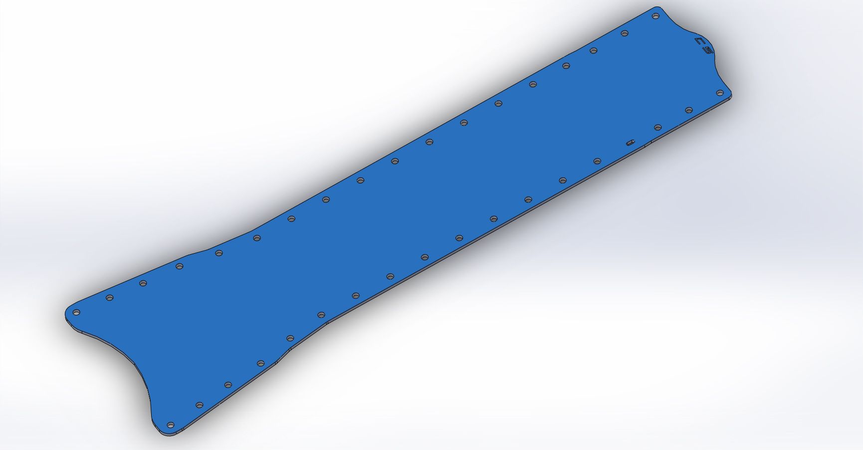

Tunnel cover Cad drawing
Team Owner


Joined: Sep 2001
Posts: 23,283
Likes: 906
From: Lake Elsinore, CA
I have my aftermarket plate off and conveniently leaning against my work bench so it would be a simple matter of measuring and drawing it up. The question goes to incentive . . .
Seriously, not a big deal.
Seriously, not a big deal.
Corvette Stories
The Best of Corvette for Corvette Enthusiasts

Top 10 Most Expensive Corvettes Ever Sold on Bring A Trailer
Brett Foote
10 Things Every Corvette Owner Needs (2026 Edition)
Michael S. Palmer
8 Most "Only Corvette Owners Understand" Quirks and Problems
Pouria Savadkouei
10 Reasons the C6 Z06 is Still A Performance Benchmark After 20 Years
Joe Kucinski
How Much Horsepower Every Corvette Engine "LOST" in 1972
Joe Kucinski
Top 10 DOs and DON'Ts for Protecting Your Convertible Top!
Michael S. Palmer
Top 10 Most Explosive Corvettes Ever Made: Power-to-Weight Ratio Ranked!
Joe Kucinski
150 hp to 1,250 hp: Every Corvette Generation Compared by the Specs That Matter
Joe Kucinski
8 Coolest Corvette Pace Cars (and Replicas) of All Time
Verdad GallardoTeam Owner
Joined: Sep 2001
Posts: 23,283
Likes: 906
From: Lake Elsinore, CA
 I have the model done - I patterned it after my aftermarket unit that was on my C5 for several years so it fits correctly. I'm also doing a dimensioned drawing for documentation's sake.
I'd be careful with ducting louvers since this is meant to not only stiffen, but insulate from exhaust heat as well. If you louver it, you may be allowing heat from the H/X pipe to blow into the tunnel and heat up the cabin tunnel. I attached a sheet of adhesive heat shielding to my plate and it insulates very nicely.
Racer


Joined: Apr 2015
Posts: 455
Likes: 48
From: Athens GA
I'd be careful with ducting louvers since this is meant to not only stiffen, but insulate from exhaust heat as well. If you louver it, you may be allowing heat from the H/X pipe to blow into the tunnel and heat up the cabin tunnel. I attached a sheet of adhesive heat shielding to my plate and it insulates very nicely.

If you could create a low pressure area on the bottom side of the tunnel plate, you could then force air from the engine bay area through the tunnel and out the bottom of the plate, keeping fresh cool air in the tunnel.
........in theory at least.

Team Owner
Joined: Sep 2001
Posts: 23,283
Likes: 906
From: Lake Elsinore, CA
You are correct on that. My issue with the insulation, I have some on mine BTW, is that insulation eventually allows heat transfer. And don't get me started on using aluminium as a device who's secondary objective is to insulate heat...... or again on the aftermarket solution for a steel plate is to use a material that is 1/3 the stiffness but make it 3 times as thick.
If you could create a low pressure area on the bottom side of the tunnel plate, you could then force air from the engine bay area through the tunnel and out the bottom of the plate, keeping fresh cool air in the tunnel.
........in theory at least.
If you could create a low pressure area on the bottom side of the tunnel plate, you could then force air from the engine bay area through the tunnel and out the bottom of the plate, keeping fresh cool air in the tunnel.
........in theory at least.
Anyway, I have the model and machine dwg. done. Where's the OP at - he asked for this to begin with.

Racer
Joined: Apr 2015
Posts: 455
Likes: 48
From: Athens GA
Low pressure on the bottom of the tunnel plate would mean higher pressure on the top of the plate, and would then create a force in the downward direction. However, I seriously doubt that the airflow in that area is fast enough to actually create such a force........ it probably would not even create enough airflow to cool the tunnel area.
And yes, a lot of hot air in this thread. I bought a standard aftermarket plate and bolted it up. It is fun to go through the exercise though.