


A different approach
Thread Starter
Heel & Toe


Joined: Jun 2014
Posts: 23
Likes: 5
Intro:
I wanted to share the results of a recent project. I'm a major DIY'er; if I can build something myself and save a few hundred bucks I am all about it. I'm also always looking for a solution with a more efficient approach. I wish I had more and better photos, but when I get to working on something I'm usually focused on the task at hand and not on documenting my work.
Anyway, a little background on this project. I sheared off the 3/4 synchro keys in my factory T56 in my C5Z, and the gears had ground a few times due to the broken keys, so I knew that it would likely get expensive quickly if I were to try to rebuild my existing transmission. I got a good deal on a low miles T56, this one with MM6 gear ratios, not the M12 ratios that I had from the factory. I chose this because the gearing will be better for the future power gains that will be coming eventually, as well as because the fact that the taller 1st gear equals a stronger transmission. I tore down my old transmission and it was good that I opted for a new transmission, as the 5/6 cluster gear and main shaft had the splines completely fubar'd, and this wasn't even a problem that I knew about! Research shows that this is due to hard acceleration in 5th/6th gear. Needless to say, I will be doing my passing in 4th gear and below from now on!
The cluster gear:

The main shaft:

Analyzing Other's Failures:
I knew I needed billet synchro keys and a steel 3/4 shifter, but I needed to plan out what other items I would address while I was at it. Obviously I would like the a strong drivetrain, but I also was on a budget. I was considering a 30 spline main shaft and having my pinion EDM'd for the larger spline, but I wanted to do actual research rather than just relying on the word of others to determine what needed to be done to my car. I have a decent amount of experience analyzing mechanical failures, and every instance of a Corvette main shaft failure that I have seen does not look like a typical axial shear failure (where the shaft simply is not strong enough to hold up to the twisting forces placed on it, therefore it shears apart). Here are a few examples of axial shears (fortunately none of them are mine!):
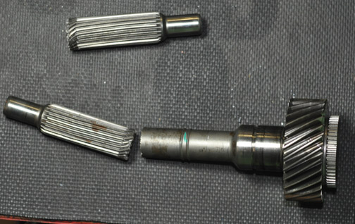
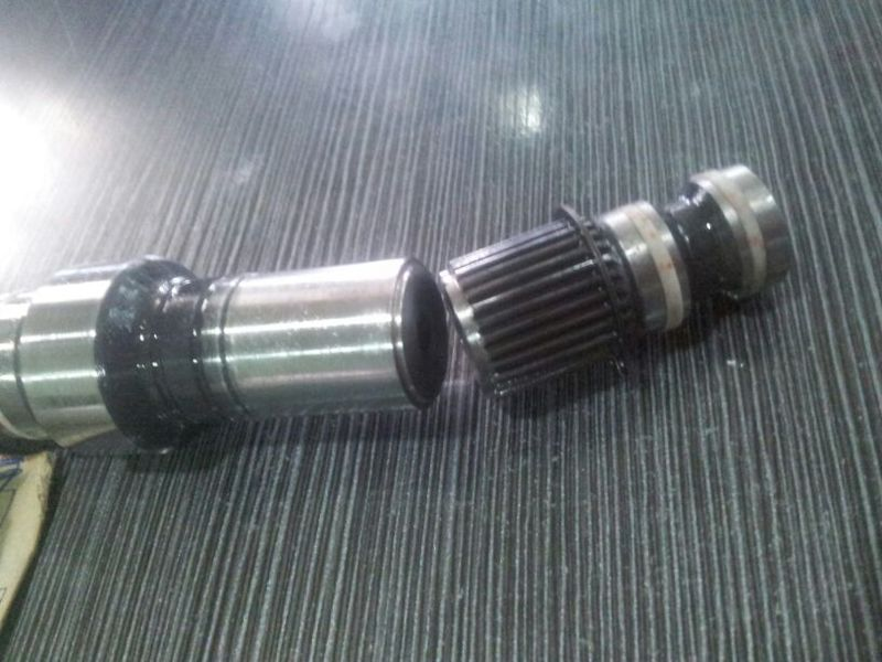


When an axial sheer failure happens, it is a surprisingly clean break. Sometimes there's a small nipple that sticks out in the very center of the break, but it is otherwise a flat surface where the two sides twist apart from one another. When analyzing Corvette main shaft failures, all looked something like this:

This is clearly not an axial sheer failure. This looks to me like a failure caused by a lateral force (think of how a stick splinters when you break it over your knee). What would cause a lateral load to be placed on the shaft? I'll get to that momentarily.
Another item that always seems to accompany a main shaft failure in a Corvette transmission is damage to the pinion bearing carrier in the differential, breaking off its mounting ears (the damage seems to be most highly concentrated on the bottom and right hand side mounting ears when looking at it from the rear). Here's an example:

As you have seen in my previous photos, an axial shear is a very clean break! It is extremely unlikely that such a failure would destroy the pinion bearing carrier, especially given the fact that the sheared off shaft section (if acted upon by a force) could simply push further into the splined pinion socket, which would eliminate any contact between the two main shaft pieces. A simple axial shear wouldn't be likely to have enough interference of moving parts to cause such a failure.
So now the question is, what would cause the mounting ears on the pinion bearing carrier to break and cause a lateral load on the main shaft, breaking it as well? My theory is that the pinion gear attempts to climb down and away from the ring gear, which breaks the pinion bearing retainer mounting ears as well as snaps the main shaft due to misalignment. The main shaft failure is not the cause, it's just the symptom! When people upgrade to a 30-spline main shaft but do not end up addressing the pinion bearing carrier, they're simply using the stronger main shaft to prevent the pinion from walking too far into a state of misalignment, which is a band-aid fix to address an inadequate pinon mounting flange. It is not good to expect the main shaft to be the thing that holds the pinon in place; that is the job of the pinion bearing retainer.
I consulted 2 individuals that I know and asked for a 2nd and 3rd opinion; one is actually a mechanical engineer who specializes in gear box design, the other is a machinist with a mechanical engineering background who used to design heavy equipment. After showing them photos of failures, as well as laying out my theory of the pinion bearing retainer being the primary point of failure, they both agreed. I am not an engineer of any sort, so needless to say it felt good to be reaffirmed by sources who's specialty is in this area.
How to Address this:
There are a few methods that I found. One is to upgrade the pinion bearing retainer itself. There are a few examples of billet aluminum ones on the market, but $450 for a machined piece of aluminum seemed a bit steep and I knew that I could come up with a solution for a fraction of the price.
Billet Aluminum Pinion Bearing Retainer

Another option is to go with a C6Z pinion bearing retainer, but that requires a C6Z ring & pinion. Although it's a lot beefier, it's still cast aluminum, which is a compromise that I was not happy about.
C6Z Left, C5/C5Z/C6 Right

I realized that all I needed was to find a solution that would prevent all of the force from being focused solely on the cast aluminum mounting ears. I machined a plate that bolts over the top of the pinion mounting flange, and the back side is stepped to match the features of the pinion bearing retainer. If it looks a little corroded that's because it is. This was a test fitting prior to finishing the surface of it to clean steel. When I was doing this, documentation was not on my mind. Fortunately, I was able to locate low profile hex cap screws and design the reinforcement plate to fit under the factory differential cover with zero modifications!
The Reinforcement Plate:

Being that I cannot find an example of a 27-spline main shaft failing due to actual insufficient ability to handle axial load I'm not convinced that it is necessarily a major weak point. Is a 30-spline shaft better? Sure, but I don't think it's necessarily required for a street car of any power output, but I'm certainly not here to tell anybody not to buy one.
Other Work Done:
I wanted a transmission brace to help prevent case twisting, just as is available through a handful of vendors. I went ahead and built one myself. There's not much special to show with this, as I more or less copied the design of what is already available.

Another issue that the C5 has is that the differential is only mounted in the middle, which allows it to rock left to right, causing wheel hop. I also really wanted to build a Pfadt style brace to prevent this (it accomplishes this by giving the differential mount a wide base, on which it cannot rock), but I also wanted to find a way to use less material if possible. I figured out exactly how to do that, using adjustable length rods with heim joints to connect my home made transmission brace down to the subframe. I can say that the difference is night and day! The power delivery is INSTANT, which tells me that the drivetrain was moving a considerable amount before, and I had no idea how much it was moving!
Pfadt Brace:

Right Side Differential Brace:

Left Side Differential Brace:

Rear Shot Showing Both:

I wanted to share the results of a recent project. I'm a major DIY'er; if I can build something myself and save a few hundred bucks I am all about it. I'm also always looking for a solution with a more efficient approach. I wish I had more and better photos, but when I get to working on something I'm usually focused on the task at hand and not on documenting my work.
Anyway, a little background on this project. I sheared off the 3/4 synchro keys in my factory T56 in my C5Z, and the gears had ground a few times due to the broken keys, so I knew that it would likely get expensive quickly if I were to try to rebuild my existing transmission. I got a good deal on a low miles T56, this one with MM6 gear ratios, not the M12 ratios that I had from the factory. I chose this because the gearing will be better for the future power gains that will be coming eventually, as well as because the fact that the taller 1st gear equals a stronger transmission. I tore down my old transmission and it was good that I opted for a new transmission, as the 5/6 cluster gear and main shaft had the splines completely fubar'd, and this wasn't even a problem that I knew about! Research shows that this is due to hard acceleration in 5th/6th gear. Needless to say, I will be doing my passing in 4th gear and below from now on!
The cluster gear:
The main shaft:
Analyzing Other's Failures:
I knew I needed billet synchro keys and a steel 3/4 shifter, but I needed to plan out what other items I would address while I was at it. Obviously I would like the a strong drivetrain, but I also was on a budget. I was considering a 30 spline main shaft and having my pinion EDM'd for the larger spline, but I wanted to do actual research rather than just relying on the word of others to determine what needed to be done to my car. I have a decent amount of experience analyzing mechanical failures, and every instance of a Corvette main shaft failure that I have seen does not look like a typical axial shear failure (where the shaft simply is not strong enough to hold up to the twisting forces placed on it, therefore it shears apart). Here are a few examples of axial shears (fortunately none of them are mine!):
When an axial sheer failure happens, it is a surprisingly clean break. Sometimes there's a small nipple that sticks out in the very center of the break, but it is otherwise a flat surface where the two sides twist apart from one another. When analyzing Corvette main shaft failures, all looked something like this:
This is clearly not an axial sheer failure. This looks to me like a failure caused by a lateral force (think of how a stick splinters when you break it over your knee). What would cause a lateral load to be placed on the shaft? I'll get to that momentarily.
Another item that always seems to accompany a main shaft failure in a Corvette transmission is damage to the pinion bearing carrier in the differential, breaking off its mounting ears (the damage seems to be most highly concentrated on the bottom and right hand side mounting ears when looking at it from the rear). Here's an example:
As you have seen in my previous photos, an axial shear is a very clean break! It is extremely unlikely that such a failure would destroy the pinion bearing carrier, especially given the fact that the sheared off shaft section (if acted upon by a force) could simply push further into the splined pinion socket, which would eliminate any contact between the two main shaft pieces. A simple axial shear wouldn't be likely to have enough interference of moving parts to cause such a failure.
So now the question is, what would cause the mounting ears on the pinion bearing carrier to break and cause a lateral load on the main shaft, breaking it as well? My theory is that the pinion gear attempts to climb down and away from the ring gear, which breaks the pinion bearing retainer mounting ears as well as snaps the main shaft due to misalignment. The main shaft failure is not the cause, it's just the symptom! When people upgrade to a 30-spline main shaft but do not end up addressing the pinion bearing carrier, they're simply using the stronger main shaft to prevent the pinion from walking too far into a state of misalignment, which is a band-aid fix to address an inadequate pinon mounting flange. It is not good to expect the main shaft to be the thing that holds the pinon in place; that is the job of the pinion bearing retainer.
I consulted 2 individuals that I know and asked for a 2nd and 3rd opinion; one is actually a mechanical engineer who specializes in gear box design, the other is a machinist with a mechanical engineering background who used to design heavy equipment. After showing them photos of failures, as well as laying out my theory of the pinion bearing retainer being the primary point of failure, they both agreed. I am not an engineer of any sort, so needless to say it felt good to be reaffirmed by sources who's specialty is in this area.
How to Address this:
There are a few methods that I found. One is to upgrade the pinion bearing retainer itself. There are a few examples of billet aluminum ones on the market, but $450 for a machined piece of aluminum seemed a bit steep and I knew that I could come up with a solution for a fraction of the price.
Billet Aluminum Pinion Bearing Retainer
Another option is to go with a C6Z pinion bearing retainer, but that requires a C6Z ring & pinion. Although it's a lot beefier, it's still cast aluminum, which is a compromise that I was not happy about.
C6Z Left, C5/C5Z/C6 Right
I realized that all I needed was to find a solution that would prevent all of the force from being focused solely on the cast aluminum mounting ears. I machined a plate that bolts over the top of the pinion mounting flange, and the back side is stepped to match the features of the pinion bearing retainer. If it looks a little corroded that's because it is. This was a test fitting prior to finishing the surface of it to clean steel. When I was doing this, documentation was not on my mind. Fortunately, I was able to locate low profile hex cap screws and design the reinforcement plate to fit under the factory differential cover with zero modifications!
The Reinforcement Plate:
Being that I cannot find an example of a 27-spline main shaft failing due to actual insufficient ability to handle axial load I'm not convinced that it is necessarily a major weak point. Is a 30-spline shaft better? Sure, but I don't think it's necessarily required for a street car of any power output, but I'm certainly not here to tell anybody not to buy one.
Other Work Done:
I wanted a transmission brace to help prevent case twisting, just as is available through a handful of vendors. I went ahead and built one myself. There's not much special to show with this, as I more or less copied the design of what is already available.
Another issue that the C5 has is that the differential is only mounted in the middle, which allows it to rock left to right, causing wheel hop. I also really wanted to build a Pfadt style brace to prevent this (it accomplishes this by giving the differential mount a wide base, on which it cannot rock), but I also wanted to find a way to use less material if possible. I figured out exactly how to do that, using adjustable length rods with heim joints to connect my home made transmission brace down to the subframe. I can say that the difference is night and day! The power delivery is INSTANT, which tells me that the drivetrain was moving a considerable amount before, and I had no idea how much it was moving!
Pfadt Brace:
Right Side Differential Brace:
Left Side Differential Brace:
Rear Shot Showing Both:
Administrator


Joined: Mar 2001
Posts: 368,744
Likes: 24,887
From: In a parallel universe. Currently own 2014 Stingray Coupe.
C7 of the Year - Modified Finalist 2021
MO Events Coordinator
St. Jude Co-Organizer
St. Jude Donor '03 thru '26
NCM Sinkhole Donor
CI 5, 8 & 11 Veteran
Thanks for the good write-up. 
Instructor
Joined: Aug 2013
Posts: 169
Likes: 16
I like this diff mount solution. Question on the phadt original mount, Maybe im not understanding that mounting scheme, does that brace mount to the diff case where you have circled? Or does it just rest on pads there?
Last edited by tungstenfoot; Mar 14, 2017 at 05:58 AM.
Thread Starter
Heel & Toe
Joined: Jun 2014
Posts: 23
Likes: 5
The Pfadt mount is actually a pretty great design. It gives the differential a wide base to prevent rocking (the further apart the supports are on anything the more resistance it will have to rolling). When the differential tries to rock, the polyurethane feet absorb the torque and prevent it from moving very far.
My design works on the same principal, but I was looking for a method that would integrate with the rest of the bracing that I had already built.
Last edited by Z06Luke; Mar 14, 2017 at 11:04 AM.
Racer

Joined: Apr 2015
Posts: 455
Likes: 49
From: Athens GA
I really like your approach. It is all too easy to beef it up, but sometimes you have to take a step back and consider the failure and what needs to be improved, it may not be the part that breaks.
I've not torn down a Vette transmission / rear end group, but overall , I think you are moving in the right direction.
I can't help but wonder if the support brace on the pinion bearing retainer is even necessary with the differential mount that you created. If that keeps the diff from trying to walk, then the force is only rotational like it was designed.
I'm not suggesting that you remove it and go do burnouts, for science........ or am I?
I think I love the mount setup that you made because of the way it integrates everything into one structure. Do you feel like more vibration is making it through the chassis? The Pfadt mount seems like it still allows movement, so I don't love that, but then it probably absorbs vibration.......
Anywho, I like the new approach.
Corvette Stories
The Best of Corvette for Corvette Enthusiasts

5 Best & 5 Worst Corvette Daily Drivers
Joe Kucinski
The Headlights of Every Corvette Generation Explained
Joe Kucinski
5 Best & 5 Most Overrated Corvette Track Packages of All Time!
Joe Kucinski
Every 2027 Corvette Engine Explained
Joe Kucinski
Designer Imagines A Corvette That Looks More Like a Corvette Than the Corvette
Verdad Gallardo
10 Ugly Corvettes That We Still Kinda Love
Joe Kucinski
Top 10 Most Expensive Corvettes Ever Sold on Bring A Trailer
Brett Foote
10 Things Every Corvette Owner Needs (2026 Edition)
Michael S. Palmer
8 Most "Only Corvette Owners Understand" Quirks and Problems
Pouria Savadkouei
Thread Starter
Heel & Toe
Joined: Jun 2014
Posts: 23
Likes: 5
I can't help but wonder if the support brace on the pinion bearing retainer is even necessary with the differential mount that you created. If that keeps the diff from trying to walk, then the force is only rotational like it was designed.
I'm not suggesting that you remove it and go do burnouts, for science........ or am I?
I'm not suggesting that you remove it and go do burnouts, for science........ or am I?
I think I love the mount setup that you made because of the way it integrates everything into one structure. Do you feel like more vibration is making it through the chassis? The Pfadt mount seems like it still allows movement, so I don't love that, but then it probably absorbs vibration.......
Anywho, I like the new approach.
Anywho, I like the new approach.
see what the result of vibration will be like with those.
Thread Starter
Heel & Toe
Joined: Jun 2014
Posts: 23
Likes: 5

Thread Starter
Heel & Toe
Joined: Jun 2014
Posts: 23
Likes: 5
Today was the first day that I've really had a chance to take the car out and beat on it a bit. This could be all in my head, but I truly believe that the car handles better than it ever has before! The cornering seems significantly more stable! I think the drive train has a tendency to shift under hard cornering, providing uneven power output down to the ground. I passed this on nothing other then being a guy who knows his car.
Thread Starter
Heel & Toe
Joined: Jun 2014
Posts: 23
Likes: 5
Safety Car

Joined: Mar 2016
Posts: 3,534
Likes: 432
From: Atlantic Beach FL.
I have been trying to justify getting one. I guess it would make a good dash cam when you are not diagnosing suspension problems.
I saw a Fast And Loud episode where the camera view was from under the car and it gave me the idea.
I saw a Fast And Loud episode where the camera view was from under the car and it gave me the idea.

Drifting


Joined: Apr 2015
Posts: 1,893
Likes: 295
From: Buffalo NY
Really cool setup, I like your solution to the trans mount. When I dropped my 2000 FRC drivetrain I was SHOCKED at how much movement was allowed between the diff and cradle. I thought for sure the mount had ripped, but it looked new.

