Proper crankcase evacuation for Turbo and Centri builds
#61
Team Owner


I did not want to reduce anything from what the entire system is running (-8AN or 1/2") right now
Looking forward to seeing how it all works out - I do like and understand the concept, plus I do like the way it will drain any oil it may catch back into the valve cover - or as we call it "Mist" that the FRC's catch at times

Thanks,Matt
#62
Melting Slicks


Thread Starter
I talked with them there and they did the -8AN for an additional $10 
I did not want to reduce anything from what the entire system is running (-8AN or 1/2") right now
Looking forward to seeing how it all works out - I do like and understand the concept, plus I do like the way it will drain any oil it may catch back into the valve cover - or as we call it "Mist" that the FRC's catch at times
Thanks,Matt

I did not want to reduce anything from what the entire system is running (-8AN or 1/2") right now
Looking forward to seeing how it all works out - I do like and understand the concept, plus I do like the way it will drain any oil it may catch back into the valve cover - or as we call it "Mist" that the FRC's catch at times

Thanks,Matt

#63
Team Owner


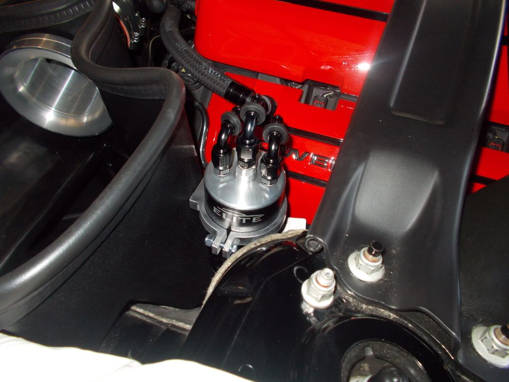
I just recently did do the 1LE cap on my Vette and took pictures etc for a write-up -
But had a bad wreck - post #4 https://www.corvetteforum.com/forums...bad-wreck.html
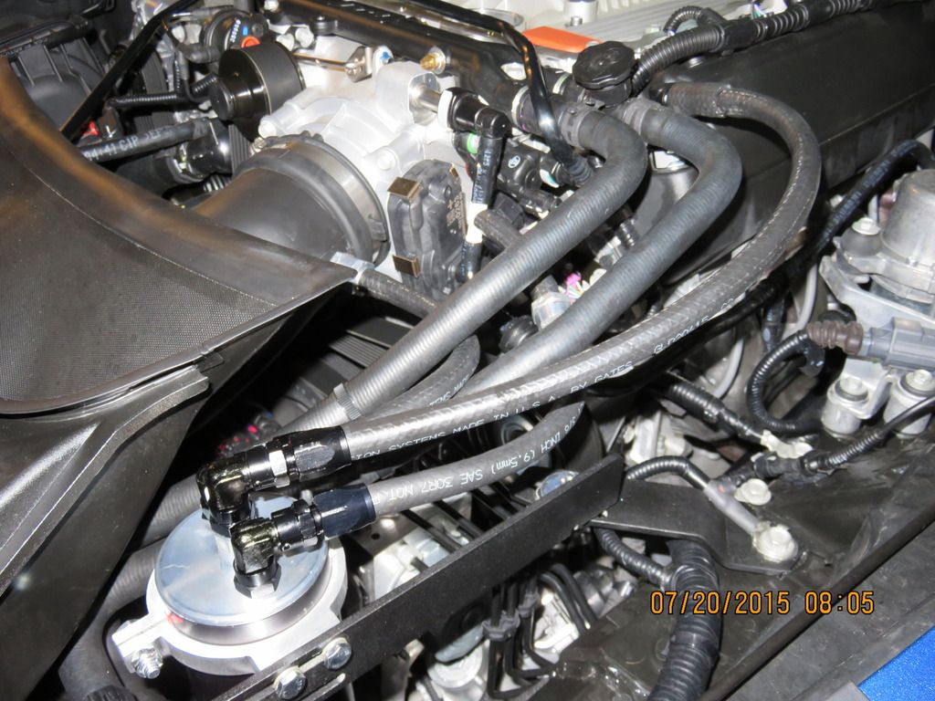
- I will post some pictures of the set-up and routing in conjunction with the rest of what I had before the wreck
Thanks,Matt
But had a bad wreck - post #4 https://www.corvetteforum.com/forums...bad-wreck.html
- I will post some pictures of the set-up and routing in conjunction with the rest of what I had before the wreck
Thanks,Matt
#64
Melting Slicks


Thread Starter
Dang Matt!!! Glad your OK! Car can be replaced, you can't be. Let me know if there is anything I can do to help.
#65
Melting Slicks


Thread Starter
Hey guys and gals. We are running the January special on the catch cans. Here is the link:
http://www.coloradospeed.com/?main_p...ha_filter_id=0
NOW is the time to get one if you need one. Not everyone will need a catch can but by the disucssion, it is a good thing to have. We'll never do this price again on these so January is the month. Thanks!
http://www.coloradospeed.com/?main_p...ha_filter_id=0
NOW is the time to get one if you need one. Not everyone will need a catch can but by the disucssion, it is a good thing to have. We'll never do this price again on these so January is the month. Thanks!
#67
Melting Slicks


Thread Starter
Any technical questions, just ask. Understanding all of this is key.
#68
Burning Brakes


Well even if you already answered douzen of my own question by pm i would like to you ask anotehr one(hope the last since all my line except the blower inlet one are done.).
While i do agree with the use of a check valve between the can and intake, i just dont understand the purpose of the one between the blower inlet and can ???
The intake is what i called in vaccum mode when idling or when cruising wich is good since it suck bad crankase gas.When boost build up the intake became pressurize and you need a check valve to prevent any boost in the can.This i agree.
For the blower inlet part.When you start the engine, the blower spin so its already creating a small vaccum.While cruising it would spin a little faster and yet creating vaccum.When you go full throttle (wot) the blower inlet create a huge vaccum wich is good since it suck bad crankcase gas.
But it will never pressurize air in the intake dongle(wich isnt a sealed piece like an intake manifold) neither in the line between the blower inlet and the can.Even if you got WOT and totally left the throttle to go neutral/idle the air dongle will not be pressurize since the blower dont push air out, it only suck air in...
To my understanding the line between the blower inlet and can will always be in vaccum mode, way more at WOT but always in vaccum...So why a check valve ?
So maybe im wrong but could you explain why a check valve is needed between the blower inlet and side of the can ???
Thanks
Eric
Last edited by always faster; 01-11-2016 at 08:39 AM.
#69
Melting Slicks


Thread Starter
Well even if you already answered douzen of my own question by pm i would like to you ask anotehr one(hope the last since all my line except the blower inlet one are done.).
While i do agree with the use of a check valve between the can and intake, i just dont understand the purpose of the one between the blower inlet and can ???
The intake is what i called in vaccum mode when idling or when cruising wich is good since it suck bad crankase gas.When boost build up the intake became pressurize and you need a check valve to prevent any boost in the can.This i agree.
For the blower inlet part.When you start the engine, the blower spin so its already creating a small vaccum.While cruising it would spin a little faster and yet creating vaccum.When you go full throttle (wot) the blower inlet create a huge vaccum wich is good since it suck bad crankcase gas.
But it will never pressurize air in the intake dongle(wich isnt a sealed piece like an intake manifold) neither in the line between the blower inlet and the can.Even if you got WOT and totally left the throttle to go neutral/idle the air dongle will not be pressurize since the blower dont push air out, it only suck air in...
To my understanding the line between the blower inlet and can will always be in vaccum mode, way more at WOT but always in vaccum...So why a check valve ?
So maybe im wrong but could you explain why a check valve is needed between the blower inlet and side of the can ???
Thanks
Eric
Excellent questions and good understanding!

#70
Burning Brakes


Im using a centri so lets focus on that type .
I need a check valve between the intake and one side of the can because the intake is pressurize by the blower and the valve prevent any pressure building, simple fact,clear, case closed
But in simple word please, what would pressurize/apply some pressure in the line between the centri blower inlet and the other side of the can to justify a check valve while the blower is always turning and creating vaccum/suction away from the can ???
Already got 2 check valves(one is already installed between the intake and can) so its not a money problem just a fact that i dont see/understand where or what would push air the other way toward the can ???
By the way Jason this thread is awesome
Thanks
Eric
I need a check valve between the intake and one side of the can because the intake is pressurize by the blower and the valve prevent any pressure building, simple fact,clear, case closed

But in simple word please, what would pressurize/apply some pressure in the line between the centri blower inlet and the other side of the can to justify a check valve while the blower is always turning and creating vaccum/suction away from the can ???
Already got 2 check valves(one is already installed between the intake and can) so its not a money problem just a fact that i dont see/understand where or what would push air the other way toward the can ???
By the way Jason this thread is awesome

Thanks
Eric
#71
Melting Slicks


Thread Starter
With a centri blower, any time it is spinning you will have boost present, so a checkvalve on each source prevents any boost from the IM getting pushed back in with your primary checkvalve. The secondary valve to the Centri blower inlet, will remain closed unless the suction present from this point is greater then the IM so it will open and close as needed. When the throttle body closes you have the blow-off valve opening to prevent damage to the TB (bending blade around the shaft) and the second check valve prevents that same boost spike from pushing back into the can/separator and this into the crankcase. So in a turbo or centri application it is critical to have both. The BOV opens quickly, bit there is always still some pressure pulse present at first when the TB blade closes quickly from WOT.
I think that is what you were asking.
Also note, none of the aftermarket Centri SC systems I have looked at evacuate at all, they only vent pressure to the intake side (and most the unfiltered side of the air box) so this is critical to properly address this for engine longevity as well as preventing pressure from first building to the point of being able to vent.
Thanks for the props.
There is far more to consider when going FI than just the FI system. Anytime you are adding boost, blow-by increases and so does the amount of combustion by-products entering the crankcase with it. These by-products must be evacuated and flushed from the crankcase before they get a chance to settle and mix with the oil where they for the most part stay contaminating the engine oil and increasing wear, and then the power loss form unstable piston rings from crankcase pressure being present, etc.

#72
i just bought a spare set of valve covers and want to have a 90 degree fitting welded onto the driver side cover. what is the smallest size fitting you would recommend? could you send me a link to the appropriate fitting to use?
Last edited by directnosfogger; 01-12-2016 at 10:42 PM.
#73
Melting Slicks


Thread Starter
I would use a weld on bung like this that you can then screw a 90* AN fitting to. You need at least a -6, but a -8 for big boost is better:
http://www.jegs.com/i/ARP/070/800-8206/10002/-1
#74
Originally Posted by coSPEED2
Make sure these valve covers have baffles underneath that are at least as good as the OEM ones/ If not you will have the rocker arms near the outlet slinging a ton of oil directly into the PCV outlet.
I would use a weld on bung like this that you can then screw a 90* AN fitting to. You need at least a -6, but a -8 for big boost is better:
http://www.jegs.com/i/ARP/070/800-8206/10002/-1
I would use a weld on bung like this that you can then screw a 90* AN fitting to. You need at least a -6, but a -8 for big boost is better:
http://www.jegs.com/i/ARP/070/800-8206/10002/-1
#75
Drifting


Member Since: Aug 2005
Location: Florida, Hell's Doorstep
Posts: 1,687
Likes: 0
Received 20 Likes
on
16 Posts

Bracket mounts right to ECS bracket in front for ease of draining.
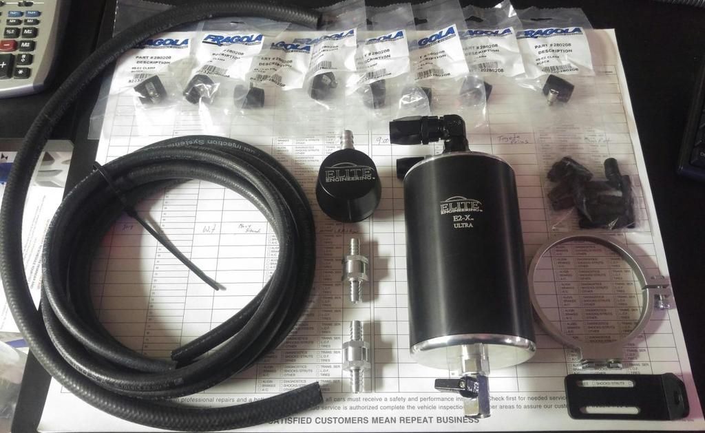
The price includes over $100 of AN fittings and billet checkvalves as well as chrome brass 1/4 turn ball valve for drain. Nothing to clean due to internal design, but we also have the Elite E2-X take apart versions as well for same applications. You wont find a more effective separator than either of these. You can place one inline behind any other can and it will catch as much or more than the first can doing its best, and do it in reverse and see almost none get past these.
Let me find pics for you. Lots of cheaper units out there, but none more effective. Let me know if you want to see test results done by others.

Last edited by ONE BMF; 01-21-2016 at 04:42 PM.
#76
Melting Slicks


Thread Starter
#78
Melting Slicks


Thread Starter
With a LT1, then use the valley as they have a more robust baffle underneath than the LS engines, and fresh air enters both valve covers so no stagnant areas remain.
One outlet from the main separator will have an inline checkvalve in it that runs to the intake manifold and uses the vacuum suction to evacuate when not in boost, and that valve will close when vacuum drops and boost is present so no pressure can enter the crankcase, and the second outlet with checkvalve opens and uses the suction present at the centri blowers inlet to always maintain evacuation suction on the crankcase. This prevents pressure issues and provides a more stable piston ring seal as well as always is evacuating the damaging compound and oil laden vapors out of the crankcase before they have a chance to fall and mix with the engine oil. So, deals with crankcase pressure, stops oil ingestion, and keeps oil cleaner as well as better ring seal for power and less wear.
Let me know if your following it all.
#80
Melting Slicks


Thread Starter


