


Rocker Arm Upgrade Procedure
Thread Starter
Burning Brakes

Joined: Nov 2007
Posts: 1,083
Likes: 3
From: Buena Park CA
For those of you who are DIYer’s like I am, here’s a procedure I used to upgrade the OEM rocker arms with a set of aftermarket roller-tipped rocker arms.
Keep in mind, replacing the OEM 1.7:1 rocker arms with a set of 1.85:1 rocker arms, like I’m using here, is not as good performance-wise as replacing the OEM camshaft with an aftermarket camshaft. Replacing the camshaft gives you the ability to have higher valve lift than the aftermarket rocker arms, a different profile of cam lobes to yield different opening and closing rates of the valves, different overlaps of intake and exhaust valves, and finally a different mechanical valve timing with respect to the crankshaft; such as 4 degrees advanced for the low RPM torque guys (like me) or 4 degrees retarded for you high RPM lovers. All a new set of roller rockers will do is increase the valve lift (as in this case for an LS2 engine with a stock camshaft) from the OEM .520” up to about .565” allowing it to breath a little easier; for a stock engine this can be an increase of about 15HP, but if you have done modifications to the intake and exhaust, then it could be complemented by yielding an increase somewhere from 20-25HP. The advantage of replacing the camshaft is you’ll get more HP than the rockers will give you, but the drawback is you’ll have to remove the radiators, the accessories on the front of the engine, disconnecting and moving the steering rack and pinion, removing the crankshaft pulley, and of course, tearing some of the engine apart. However, by simply upgrading the rocker arms, you only need to remove the valve covers. The radiators don’t have to come out, the accessories don’t have to be removed, the rack and pinion doesn’t have to be disconnected and moved out of the way, the crankshaft pulley stays on, etc, etc. To upgrade the camshaft is extremely labor-intensive, and I’ve done many of them, but upgrading the rocker arms isn’t, so it just depends on what you want to accomplish. Are you ready? Here we go….
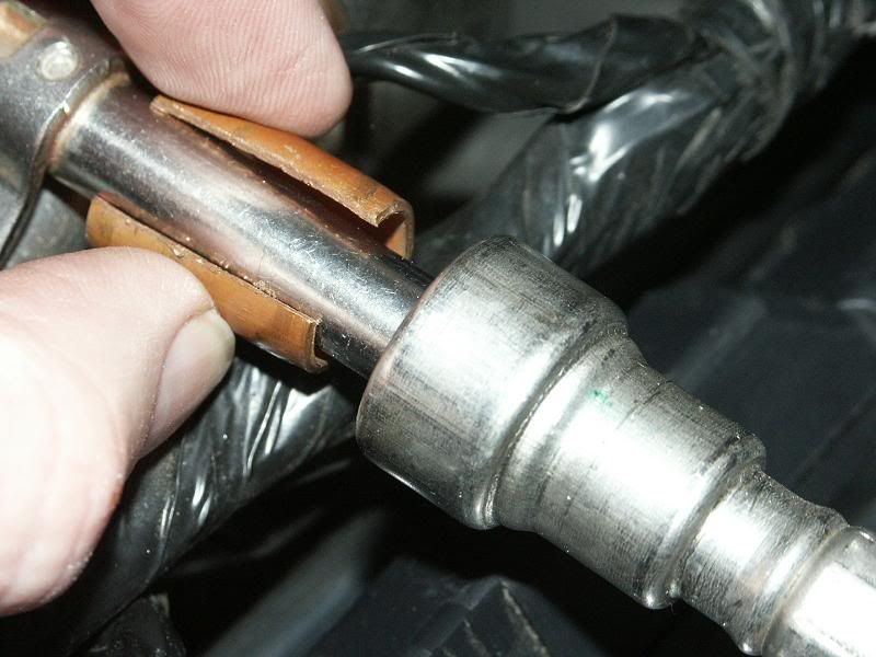
If you don’t have the proper tool for removing the fuel line from the fuel rail, here’s a simple idea to accomplish that. Get a piece of 3/8” copper tubing and cut it to about �” in length. Then, cut that piece length-wise on one side so you can open it up with a screwdriver. The picture below shows that piece of copper pipe that I have slipped onto the fuel rail after I cut it with a hacksaw. Now, all you have to do is squeeze it with your fingers to close it up around the fuel rail and again with your fingers slide by pushing it into the fuel connector as far as it will go. This will push back the internal fingers of the connector where all you have to do is pull on the fuel line to release it. Then, use a screwdriver to re-open the copper piece to remove it from the fuel rail. Save this in your toolbox, you may need it in the future.
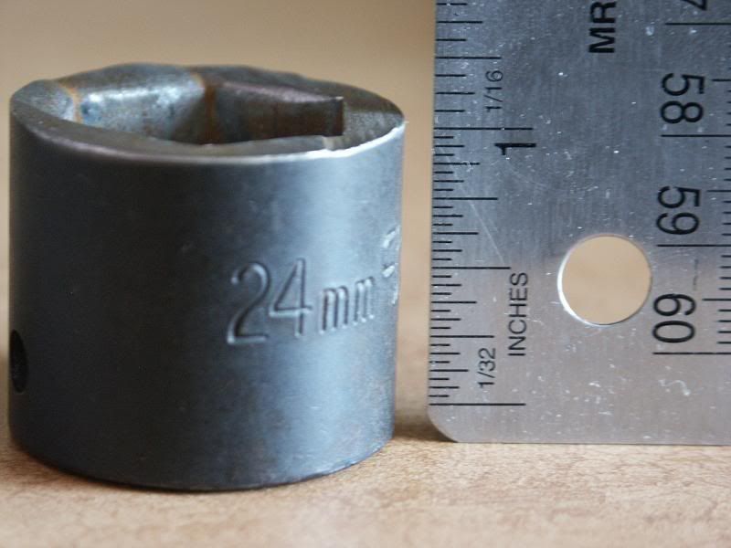
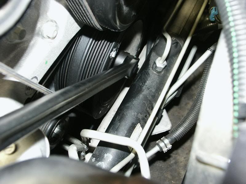
Once you install a new set of rocker arms, they have to be adjusted (properly set to a pre-load). So, in order to do this, you must be able to manually rotate the crankshaft by the balancer bolt using a socket and a breaker bar enabling you to adjust both valves for each cylinder. You’ll notice this can’t be done with an ordinary socket as it is too long such that the steering rack and pinion assembly is right in the way; there is just not enough room to get in there. So, the picture below shows where I took my 24mm impact socket I had, that I have never used for anything else, and had it cut down to a length of 1 1/8”. With this socket and the breaker bar, I was easily able to get onto the pulley bolt with enough bite and manually rotate the crankshaft without removing the steering rack and pinion assembly. You’ll be accessing the bolt for rotation from the passenger side.
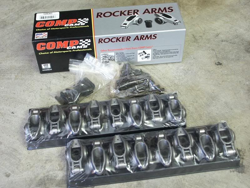
The picture below shows the roller-tipped rocker arms that I am installing. There are a lot of companies out there that make good ones, so it’s up to you what you use, but the procedure for installation is basically the same.
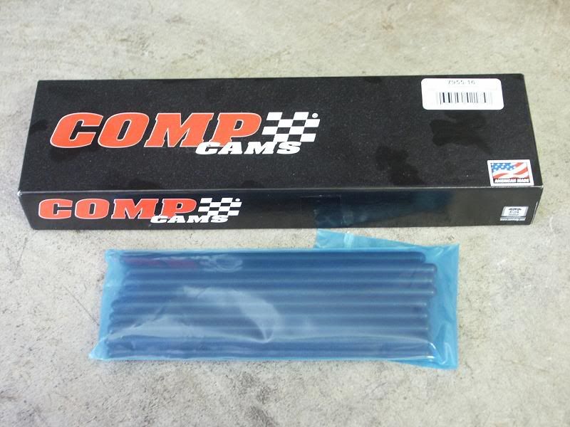
The picture below shows a new set of pushrods. It is always a good idea to purchase a new and stronger set when you are upgrading your rocker arms. It is not absolutely necessary, just my own rule of thumb, but buying the pushrods from the same manufacturer helps to ensure they are “matched” to the new rocker arms. The newer rocker arms have a higher ratio, which means they will be pushing the valves deeper into the cylinders (higher lift), this higher pressure comes from compressing the valve springs even more, therefore, the pushrods will have more force applied to them as well. They need to be stronger than the OEM’s to prevent them from bending at any RPM. Again, it’s up to you, but I highly recommend getting upgraded pushrods as well.
Clean by scrubbing with an old toothbrush all the rocker arms, rocker studs, guide plates, lock nuts, set screws and pushrods with “denatured alcohol” as shown by the picture below. This gets rid of all the manufacturing cutting oils, grease and any other contaminations. Then when dry, coat everything with oil and set aside.

Sometimes you can get away with using the OEM valve covers when upgrading to higher ratio rocker arms, but due to different manufacturing tolerances in everything, you may find yourself hearing them ticking or knocking on the covers; obviously not a good thing. So, to eliminate all that possible future hassle, I have elected to purchase a set of billet valve covers as shown here that are slightly taller than the OEM’s. If you want to know who these covers are from and my experience with them, PM me and I’ll let you know.
When replacing the valve covers, always get a new set of gaskets. Here’s a set of Felpro’s I got from Summit Racing. They fit perfectly.
Now to the dismantling.... Disconnect the battery cable going to the fuse box as shown in the picture below. You don’t necessarily have to do this, but my experience has shown that Murphy’s Law will again bite you if you don’t; I have witnessed (and participated) in some of the stupidest things that can happen while you’re trying to get stuff done. I’ve seen a washer being dropped down a slot in the alternator which effectively burned out the internal regulator, or a socket is dropped down to the starter area that lodges itself between the positive cable and the casing causing the battery cable to get so hot that they begin to melt before we had a chance to disconnect the battery (this is an easy and fun way to start an engine fire!), and of course accidentally touching a hot connection with a wrench causing sparks along with gas fumes aerating around you is also enlightening. Disconnecting the "Negative" battery cable ensures you won’t have stupid results when stupid things happen, so make sure you do this.
Next, remove the air intake system you have up to the throttlebody so you have access down the front of the engine to the crankshaft pulley. In the picture below, my TB is missing because I sent it out to exchange it for a ported TB, so while I was waiting for that I decided to do this rocker arm upgrade. Next, drain the some of the anti-freeze out of the engine just enough so there isn’t any in the upper radiator hose; I was able to do this without raising the front of the car. Then, disconnect the large and small hoses from the engine as shown by the arrows and move them out of the way.
The next removable parts are fairly straightforward, so I didn’t include pictures that would insult your intelligence. Remove all the electrical connections from the coils and the sensor. Remove the plug wires from the coils. Remove the coils from the brackets. Remove the coil brackets from the valve covers. Remove the fuel injector harnesses from the brackets (obviously, you’ll be reusing them). And finally, remove the OEM valve covers. Clean the head surface area to make sure there is no debris when installing the new valve covers.
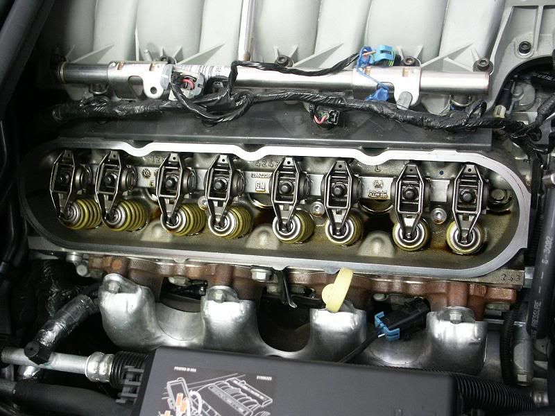
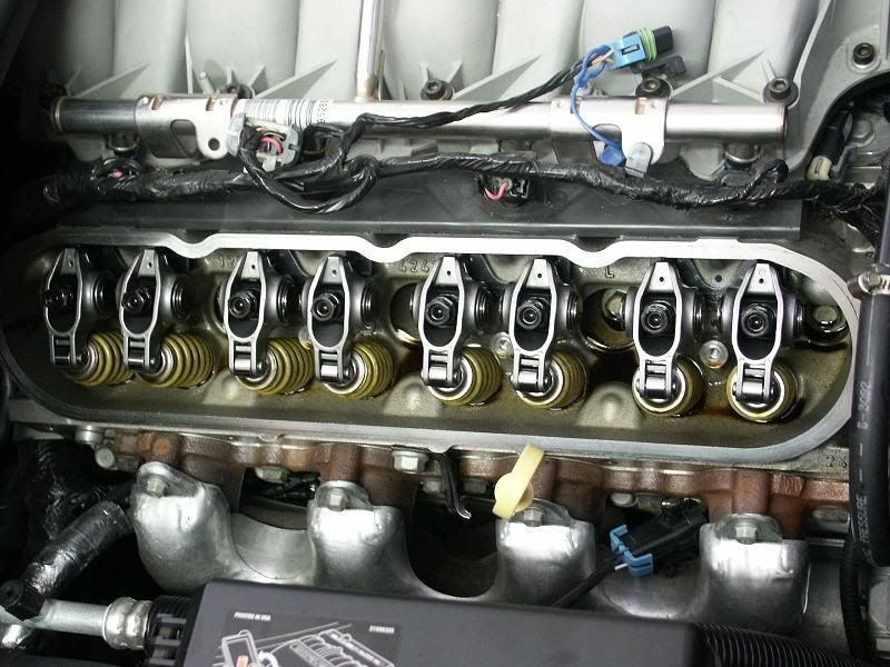
The picture below shows the OEM rocker arms. Before removing these, you are going to make sure the engine is at TDC for the #1 cylinder. So, manually rotate the crankshaft while watching the movement of the #6 exhaust rocker arm. When you see this rocker arm coming up from previously being compressed, also watch the #6 intake rocker arm at the same time. When you notice the exhaust rocker arm is about to stop moving upward and the intake rocker arm is just starting to move downward, then STOP rotating the crankshaft. You are now at TDC for cylinder #1 (the opposite of cylinder #6).
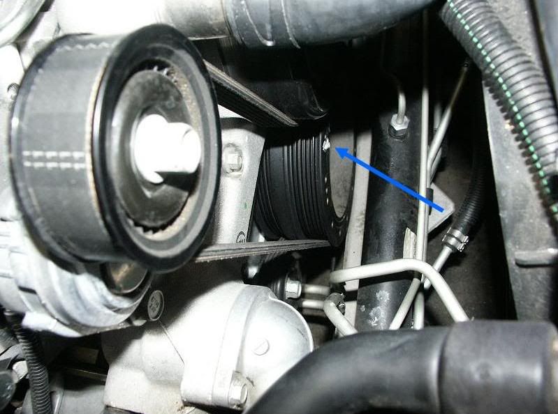
The picture below shows I have picked a reference point on the crankshaft pulley where I marked it with some White-Out where I used it to align with the bolt on the belt tensioner pulley above. Again, this is the position of the crankshaft for the TDC location of the #1 cylinder; our reference point.
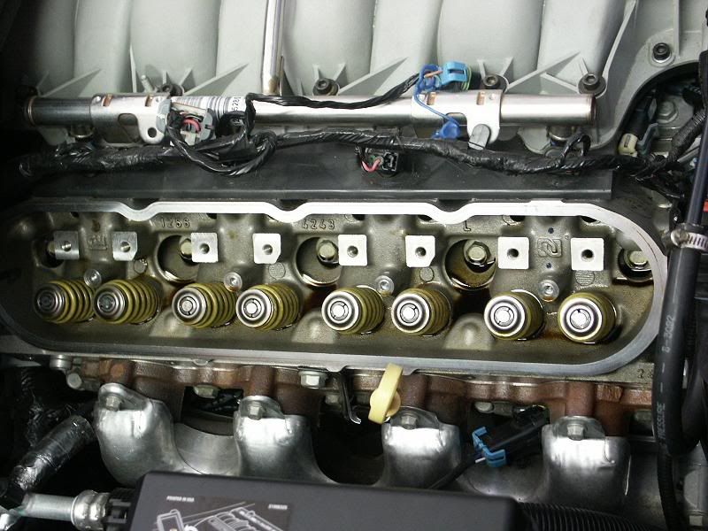
Now, remove the OEM rocker arms, the pivot supports and the push rods for all the cylinders. The picture below shows the passenger side after the removal.
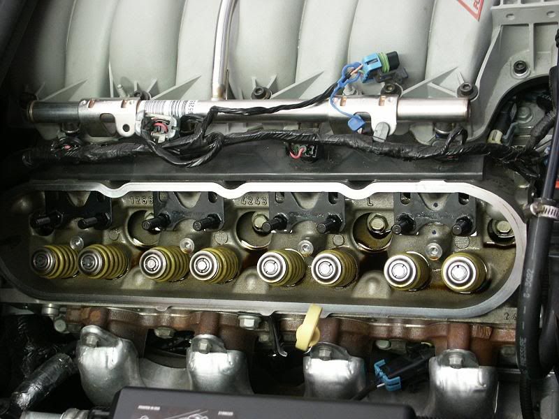
Now for the installation. It’s not necessary, but good insurance to use a small dab of Permatex Ultra Black silicone sealer on the threads of the rocker arm studs (for the head side, not the rocker arm side) to help prevent them from ever coming loose. Install the guide plates with the studs and torque them all down to 25 lb-ft. The picture below shows the passenger side with the plates and studs installed.
Now, install the new pushrods and the new rocker arms. Make sure the set screws in the lock nuts are all the way out (basically flush with the nuts) and lightly finger tighten all the nuts onto the rocker arms. The picture below shows the passenger side with the new rocker arms installed.
Because we have already set the crankshaft to TDC for the #1 cylinder, we can immediately adjust both the intake and exhaust valves for #1. Do this by tightening the rocker arm nut while rotating the pushrod between your thumb and forefinger until you feel a point which there will be slight resistance (you may have to loosen the lock nut to start over). At this point, all the excess slack has been taken out of the pushrod. You are now at “zero lash”. Then, turn the lock nut 5/8 turn more and tighten the set screw. Do this for both the intake and exhaust rocker arms for the #1 cylinder.
As shown in the picture below, manually rotate the crankshaft 90 degrees (do this in small increments to allow the compression in the cylinders to be released) and repeat the above procedure for the #8 cylinder and so on until both intake and exhaust rocker arms for each cylinder have been adjusted; the firing order is 1-8-7-2-6-5-4-3 and will take you two crankshaft revolutions to complete the rocker arm adjustments.
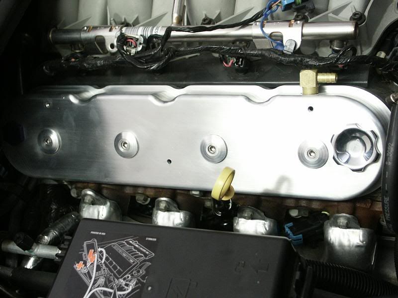
Once all the rocker arm adjustments have been made, install the new valve covers as shown below and torque them to 106 lb-in.
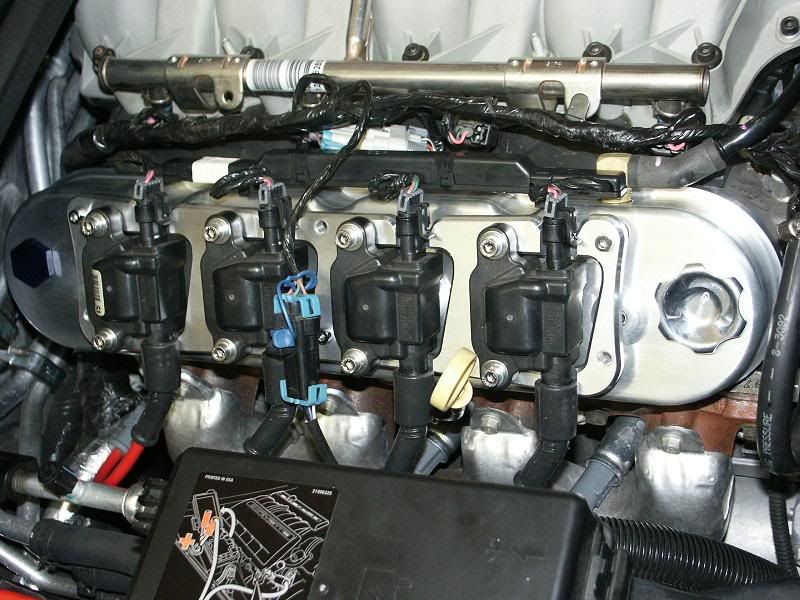
The rest is easy, install the new brackets, coils and plug wires. Then, position the fuel injector harnesses somewhere above the valve covers and reconnect the electrical connections to the coils and sensor all as shown in the picture below.
Finish up by re-attaching the two water hoses to the engine, reconnecting the air intake system (including the hose from the passenger valve cover to the IAT sensor), reconnect the fuel line to the fuel rail, reconnect the battery, and fill the engine with the antifreeze solution you drained earlier. When you first fire the engine up, you will more than likely hear a lot of lifter noise until they pump themselves up along with the pushrods with oil and into the rocker arms, then they should be quiet. You’re done, and I hope this helps any of you DIYer’s out!
Keep in mind, replacing the OEM 1.7:1 rocker arms with a set of 1.85:1 rocker arms, like I’m using here, is not as good performance-wise as replacing the OEM camshaft with an aftermarket camshaft. Replacing the camshaft gives you the ability to have higher valve lift than the aftermarket rocker arms, a different profile of cam lobes to yield different opening and closing rates of the valves, different overlaps of intake and exhaust valves, and finally a different mechanical valve timing with respect to the crankshaft; such as 4 degrees advanced for the low RPM torque guys (like me) or 4 degrees retarded for you high RPM lovers. All a new set of roller rockers will do is increase the valve lift (as in this case for an LS2 engine with a stock camshaft) from the OEM .520” up to about .565” allowing it to breath a little easier; for a stock engine this can be an increase of about 15HP, but if you have done modifications to the intake and exhaust, then it could be complemented by yielding an increase somewhere from 20-25HP. The advantage of replacing the camshaft is you’ll get more HP than the rockers will give you, but the drawback is you’ll have to remove the radiators, the accessories on the front of the engine, disconnecting and moving the steering rack and pinion, removing the crankshaft pulley, and of course, tearing some of the engine apart. However, by simply upgrading the rocker arms, you only need to remove the valve covers. The radiators don’t have to come out, the accessories don’t have to be removed, the rack and pinion doesn’t have to be disconnected and moved out of the way, the crankshaft pulley stays on, etc, etc. To upgrade the camshaft is extremely labor-intensive, and I’ve done many of them, but upgrading the rocker arms isn’t, so it just depends on what you want to accomplish. Are you ready? Here we go….
If you don’t have the proper tool for removing the fuel line from the fuel rail, here’s a simple idea to accomplish that. Get a piece of 3/8” copper tubing and cut it to about �” in length. Then, cut that piece length-wise on one side so you can open it up with a screwdriver. The picture below shows that piece of copper pipe that I have slipped onto the fuel rail after I cut it with a hacksaw. Now, all you have to do is squeeze it with your fingers to close it up around the fuel rail and again with your fingers slide by pushing it into the fuel connector as far as it will go. This will push back the internal fingers of the connector where all you have to do is pull on the fuel line to release it. Then, use a screwdriver to re-open the copper piece to remove it from the fuel rail. Save this in your toolbox, you may need it in the future.
Once you install a new set of rocker arms, they have to be adjusted (properly set to a pre-load). So, in order to do this, you must be able to manually rotate the crankshaft by the balancer bolt using a socket and a breaker bar enabling you to adjust both valves for each cylinder. You’ll notice this can’t be done with an ordinary socket as it is too long such that the steering rack and pinion assembly is right in the way; there is just not enough room to get in there. So, the picture below shows where I took my 24mm impact socket I had, that I have never used for anything else, and had it cut down to a length of 1 1/8”. With this socket and the breaker bar, I was easily able to get onto the pulley bolt with enough bite and manually rotate the crankshaft without removing the steering rack and pinion assembly. You’ll be accessing the bolt for rotation from the passenger side.
The picture below shows the roller-tipped rocker arms that I am installing. There are a lot of companies out there that make good ones, so it’s up to you what you use, but the procedure for installation is basically the same.
The picture below shows a new set of pushrods. It is always a good idea to purchase a new and stronger set when you are upgrading your rocker arms. It is not absolutely necessary, just my own rule of thumb, but buying the pushrods from the same manufacturer helps to ensure they are “matched” to the new rocker arms. The newer rocker arms have a higher ratio, which means they will be pushing the valves deeper into the cylinders (higher lift), this higher pressure comes from compressing the valve springs even more, therefore, the pushrods will have more force applied to them as well. They need to be stronger than the OEM’s to prevent them from bending at any RPM. Again, it’s up to you, but I highly recommend getting upgraded pushrods as well.
Clean by scrubbing with an old toothbrush all the rocker arms, rocker studs, guide plates, lock nuts, set screws and pushrods with “denatured alcohol” as shown by the picture below. This gets rid of all the manufacturing cutting oils, grease and any other contaminations. Then when dry, coat everything with oil and set aside.
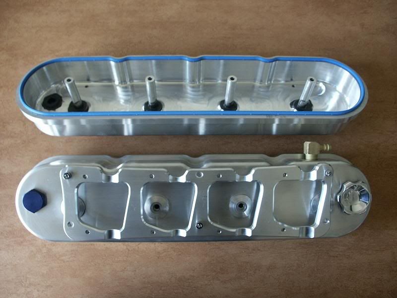
Sometimes you can get away with using the OEM valve covers when upgrading to higher ratio rocker arms, but due to different manufacturing tolerances in everything, you may find yourself hearing them ticking or knocking on the covers; obviously not a good thing. So, to eliminate all that possible future hassle, I have elected to purchase a set of billet valve covers as shown here that are slightly taller than the OEM’s. If you want to know who these covers are from and my experience with them, PM me and I’ll let you know.
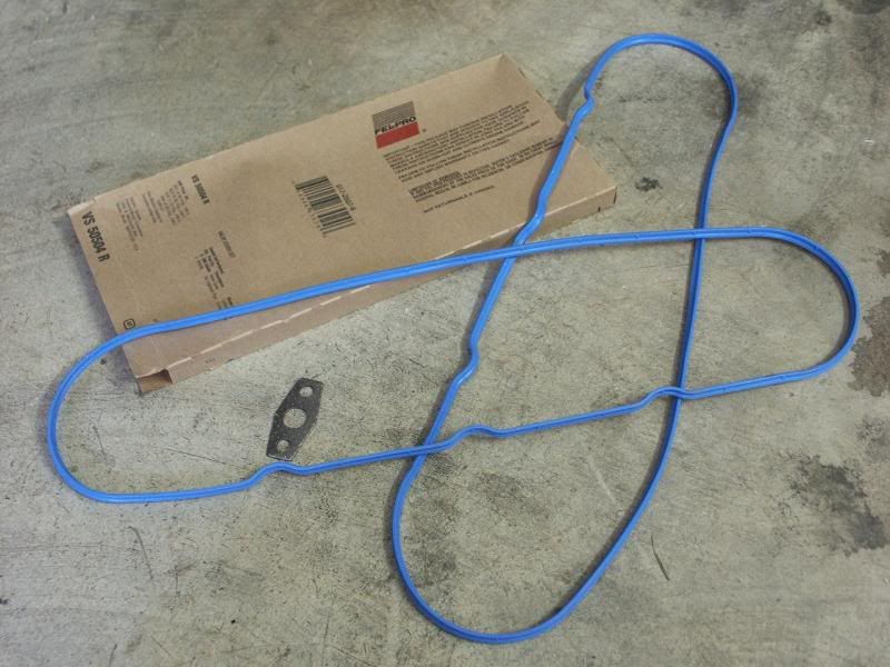
When replacing the valve covers, always get a new set of gaskets. Here’s a set of Felpro’s I got from Summit Racing. They fit perfectly.
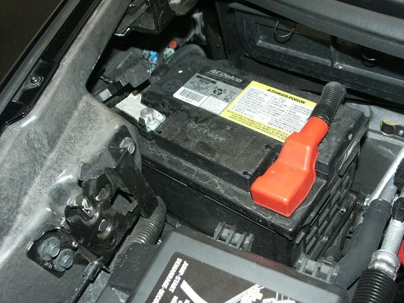
Now to the dismantling.... Disconnect the battery cable going to the fuse box as shown in the picture below. You don’t necessarily have to do this, but my experience has shown that Murphy’s Law will again bite you if you don’t; I have witnessed (and participated) in some of the stupidest things that can happen while you’re trying to get stuff done. I’ve seen a washer being dropped down a slot in the alternator which effectively burned out the internal regulator, or a socket is dropped down to the starter area that lodges itself between the positive cable and the casing causing the battery cable to get so hot that they begin to melt before we had a chance to disconnect the battery (this is an easy and fun way to start an engine fire!), and of course accidentally touching a hot connection with a wrench causing sparks along with gas fumes aerating around you is also enlightening. Disconnecting the "Negative" battery cable ensures you won’t have stupid results when stupid things happen, so make sure you do this.
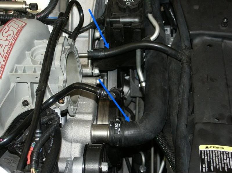
Next, remove the air intake system you have up to the throttlebody so you have access down the front of the engine to the crankshaft pulley. In the picture below, my TB is missing because I sent it out to exchange it for a ported TB, so while I was waiting for that I decided to do this rocker arm upgrade. Next, drain the some of the anti-freeze out of the engine just enough so there isn’t any in the upper radiator hose; I was able to do this without raising the front of the car. Then, disconnect the large and small hoses from the engine as shown by the arrows and move them out of the way.
The next removable parts are fairly straightforward, so I didn’t include pictures that would insult your intelligence. Remove all the electrical connections from the coils and the sensor. Remove the plug wires from the coils. Remove the coils from the brackets. Remove the coil brackets from the valve covers. Remove the fuel injector harnesses from the brackets (obviously, you’ll be reusing them). And finally, remove the OEM valve covers. Clean the head surface area to make sure there is no debris when installing the new valve covers.
The picture below shows the OEM rocker arms. Before removing these, you are going to make sure the engine is at TDC for the #1 cylinder. So, manually rotate the crankshaft while watching the movement of the #6 exhaust rocker arm. When you see this rocker arm coming up from previously being compressed, also watch the #6 intake rocker arm at the same time. When you notice the exhaust rocker arm is about to stop moving upward and the intake rocker arm is just starting to move downward, then STOP rotating the crankshaft. You are now at TDC for cylinder #1 (the opposite of cylinder #6).
The picture below shows I have picked a reference point on the crankshaft pulley where I marked it with some White-Out where I used it to align with the bolt on the belt tensioner pulley above. Again, this is the position of the crankshaft for the TDC location of the #1 cylinder; our reference point.
Now, remove the OEM rocker arms, the pivot supports and the push rods for all the cylinders. The picture below shows the passenger side after the removal.
Now for the installation. It’s not necessary, but good insurance to use a small dab of Permatex Ultra Black silicone sealer on the threads of the rocker arm studs (for the head side, not the rocker arm side) to help prevent them from ever coming loose. Install the guide plates with the studs and torque them all down to 25 lb-ft. The picture below shows the passenger side with the plates and studs installed.
Now, install the new pushrods and the new rocker arms. Make sure the set screws in the lock nuts are all the way out (basically flush with the nuts) and lightly finger tighten all the nuts onto the rocker arms. The picture below shows the passenger side with the new rocker arms installed.
Because we have already set the crankshaft to TDC for the #1 cylinder, we can immediately adjust both the intake and exhaust valves for #1. Do this by tightening the rocker arm nut while rotating the pushrod between your thumb and forefinger until you feel a point which there will be slight resistance (you may have to loosen the lock nut to start over). At this point, all the excess slack has been taken out of the pushrod. You are now at “zero lash”. Then, turn the lock nut 5/8 turn more and tighten the set screw. Do this for both the intake and exhaust rocker arms for the #1 cylinder.
As shown in the picture below, manually rotate the crankshaft 90 degrees (do this in small increments to allow the compression in the cylinders to be released) and repeat the above procedure for the #8 cylinder and so on until both intake and exhaust rocker arms for each cylinder have been adjusted; the firing order is 1-8-7-2-6-5-4-3 and will take you two crankshaft revolutions to complete the rocker arm adjustments.
Once all the rocker arm adjustments have been made, install the new valve covers as shown below and torque them to 106 lb-in.
The rest is easy, install the new brackets, coils and plug wires. Then, position the fuel injector harnesses somewhere above the valve covers and reconnect the electrical connections to the coils and sensor all as shown in the picture below.
Finish up by re-attaching the two water hoses to the engine, reconnecting the air intake system (including the hose from the passenger valve cover to the IAT sensor), reconnect the fuel line to the fuel rail, reconnect the battery, and fill the engine with the antifreeze solution you drained earlier. When you first fire the engine up, you will more than likely hear a lot of lifter noise until they pump themselves up along with the pushrods with oil and into the rocker arms, then they should be quiet. You’re done, and I hope this helps any of you DIYer’s out!
Last edited by HuskerBullet; Apr 22, 2009 at 05:40 PM. Reason: Changed battery picture.
Thread Starter
Burning Brakes
Joined: Nov 2007
Posts: 1,083
Likes: 3
From: Buena Park CA
You got me there, I don't know, but you're on the right track by asking. When you apply more lift such as with a camshaft, then you should get better springs as they will start floating at high RPM and hitting the pistons.
Thread Starter
Burning Brakes
Joined: Nov 2007
Posts: 1,083
Likes: 3
From: Buena Park CA
You might be right about the stock springs, again I don't know. But the OEM camshaft has a lobe lift of .305, so with the OEM rockers of 1.70 you have .305 x 1.70 = .519", and with the 1.85 rockers you have .305 x 1.85 = .565".
Corvette Stories
The Best of Corvette for Corvette Enthusiasts

Every 2027 Corvette Engine Explained
Joe Kucinski
Designer Imagines A Corvette That Looks More Like a Corvette Than the Corvette
Verdad Gallardo
10 Ugly Corvettes That We Still Kinda Love
Joe Kucinski
Top 10 Most Expensive Corvettes Ever Sold on Bring A Trailer
Brett Foote
10 Things Every Corvette Owner Needs (2026 Edition)
Michael S. Palmer
8 Most "Only Corvette Owners Understand" Quirks and Problems
Pouria Savadkouei
10 Reasons the C6 Z06 is Still A Performance Benchmark After 20 Years
Joe Kucinski
How Much Horsepower Every Corvette Engine "LOST" in 1972
Joe Kucinski
Top 10 DOs and DON'Ts for Protecting Your Convertible Top!
Michael S. Palmer


Thread Starter
Burning Brakes
Joined: Nov 2007
Posts: 1,083
Likes: 3
From: Buena Park CA
 for results/evaluation


Thread Starter
Burning Brakes
Joined: Nov 2007
Posts: 1,083
Likes: 3
From: Buena Park CA
As far as new valve covers, I've seen engines where they weren't necessary and others where it was. So, I think the mechanical tolerances between the rockers, pushrods, lifters, etc. are different enough that it's so close. Again, I got them to make sure I had the room and no problems later.

Drifting


Joined: Mar 2005
Posts: 1,424
Likes: 21
From: Placitas New Mexico