

Fuel level sender wiring terminals


Thread Starter
Le Mans Master


Joined: Dec 2004
Posts: 5,493
Likes: 809
From: West coast CA
Has anyone changed the fuel level sender units in a C6?
How did you release the outgoing sender's electrical terminals from the connector? They appear to be of the classic snap-in design that requires a special box-shaped tool for removal, yet the manual makes no mention of that at all. It just says "remove."
How did you release the outgoing sender's electrical terminals from the connector? They appear to be of the classic snap-in design that requires a special box-shaped tool for removal, yet the manual makes no mention of that at all. It just says "remove."


Thread Starter
Le Mans Master
Joined: Dec 2004
Posts: 5,493
Likes: 809
From: West coast CA
Like I said, GM's instructions are "remove the sender wires from the connector." That's the problem.
There is no doubt some unobtainable special tool in an AMP catalog someplace that would work, but I presume most people just end up shoving tweezers and jeweler's screwdrivers in there until the thing falls out.
There is no doubt some unobtainable special tool in an AMP catalog someplace that would work, but I presume most people just end up shoving tweezers and jeweler's screwdrivers in there until the thing falls out.

Safety Car


Joined: Sep 2007
Posts: 3,502
Likes: 82
Like I said, GM's instructions are "remove the sender wires from the connector." That's the problem.
There is no doubt some unobtainable special tool in an AMP catalog someplace that would work, but I presume most people just end up shoving tweezers and jeweler's screwdrivers in there until the thing falls out.
There is no doubt some unobtainable special tool in an AMP catalog someplace that would work, but I presume most people just end up shoving tweezers and jeweler's screwdrivers in there until the thing falls out.
One caution, when you insert that connector into the bulkhead fitting on the top of the pump it tends to want to shove those connectors back out...watch it closely because IF this happens you'll have no gauge and will be taking it all apart again....ask me how I know! I took a very small tie wrap and cinched all 4 wires together just below that connector to lessen the chance of one of those backing out

Last edited by Motorhead-47; Aug 30, 2010 at 09:41 PM.
Thread Starter
Le Mans Master
Joined: Dec 2004
Posts: 5,493
Likes: 809
From: West coast CA
I tried the jeweler's screwdriver technique with no success. Since my new pump came with a new connector, I finally took a pair of snips to the old one and "disassembled" the plastic shell permanently. The two sending unit wires then just snap into the new connector.
One caution, when you insert that connector into the bulkhead fitting on the top of the pump it tends to want to shove those connectors back out...watch it closely because IF this happens you'll have no gauge and will be taking it all apart again....ask me how I know! I took a very small tie wrap and cinched all 4 wires together just below that connector to lessen the chance of one of those backing out
One caution, when you insert that connector into the bulkhead fitting on the top of the pump it tends to want to shove those connectors back out...watch it closely because IF this happens you'll have no gauge and will be taking it all apart again....ask me how I know! I took a very small tie wrap and cinched all 4 wires together just below that connector to lessen the chance of one of those backing out
With all the level sender cards being replaced, it's amazing how little this is discussed. What are GM techs doing? Splicing wires?
Thread Starter
Le Mans Master
Joined: Dec 2004
Posts: 5,493
Likes: 809
From: West coast CA
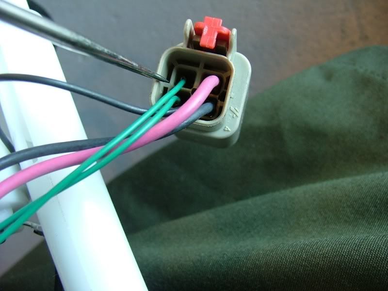
All you need is a paper clip and a flat, narrow tool such as a pair of tweezers.
Examine the backside of the connector housing. Notice the small hole in the cross-shaped intersection between the four terminal holes.
Also notice that the plastic bars that form the cross are of different thicknesses. The bar that separates the green wires from the red and black wires is thicker.
Unfold the paper clip and insert it into the center hole. Press until the blue molding on the front side of the connector snaps forward.
Next, and also from the backside of the connector, insert the flat tool into the bore of the terminal you want to remove, along the inside edge shared with the thicker plastic bar.
Push on the flat tool to deflect a plastic tang molded into the housing that retains the terminal. With the flat tool in place, pull back on the terminal wire and it should come out easily.
Last edited by torquetube; Sep 2, 2010 at 12:34 PM.

Intermediate

Joined: Oct 2008
Posts: 30
Likes: 0
From: Concordia KS
All you need is a paper clip and a flat, narrow tool such as a pair of tweezers.
Examine the backside of the connector housing. Notice the small hole in the cross-shaped intersection between the four terminal holes.
Also notice that the plastic bars that form the cross are of different thicknesses. The bar that separates the green wires from the red and black wires is thicker.
Unfold the paper clip and insert it into the center hole. Press until the blue molding on the front side of the connector snaps forward.
Next, and also from the backside of the connector, insert the flat tool into the bore of the terminal you want to remove, along the inside edge shared with the thicker plastic bar.
Push on the flat tool to deflect a plastic tang molded into the housing that retains the terminal. With the flat tool in place, pull back on the terminal wire and it should come out easily.
Examine the backside of the connector housing. Notice the small hole in the cross-shaped intersection between the four terminal holes.
Also notice that the plastic bars that form the cross are of different thicknesses. The bar that separates the green wires from the red and black wires is thicker.
Unfold the paper clip and insert it into the center hole. Press until the blue molding on the front side of the connector snaps forward.
Next, and also from the backside of the connector, insert the flat tool into the bore of the terminal you want to remove, along the inside edge shared with the thicker plastic bar.
Push on the flat tool to deflect a plastic tang molded into the housing that retains the terminal. With the flat tool in place, pull back on the terminal wire and it should come out easily.


