


CEI Code
Thread Starter
Pro


Joined: Sep 2004
Posts: 560
Likes: 1
From: Dacula GA
I just pulled a ECM code P 1682 (Manifest Control Aux Inputs and Outputs). The battery was replaced recently I googled the code and it comes up low voltage to the ECM. This car also has an aftermarket radio. The car runs normal no loss of power and the CEI goes off and comes back on ocassionally. Your thoughts and suggestions would be appreciated.
Moderator emeritus


Joined: Jun 2001
Posts: 18,599
Likes: 3,954
From: Jacksonville Florida BWO Dayton, Cincinnati, Bloomsbury NJ, Cincinnati
2015 C7 of the Year Finalist
Open or high resistance at the run/crank relay (#44?) (See Ignition 1 Switch Circuit 2, Underhood junction box) Probably the relay. Worst case is the ECM.
That's my best shot.
Elmer
That's my best shot.
Elmer
Last edited by eboggs_jkvl; Jan 30, 2011 at 12:36 PM.
Thread Starter
Pro
Joined: Sep 2004
Posts: 560
Likes: 1
From: Dacula GA
Tech Contributor


Joined: Oct 1999
Posts: 41,055
Likes: 9,817
From: Charlotte, NC (formerly Endicott, NY)
Not sure where you got the name for that code but it is definitely not related to the Vette. Here is the SM diagnostic for that code:
DTC P1682
Diagnostic Instructions
• Perform the Diagnostic System Check - Vehicle prior to using this diagnostic procedure.
• Review Strategy Based Diagnosis for an overview of the diagnostic approach.
• Diagnostic Procedure Instructions provides an overview of each diagnostic category.
DTC Descriptor
DTC P1682: Ignition 1 Switch Circuit 2
Diagnostic Fault Information
Typical Scan Tool Data
Ignition Scan Tool Data
Operating Conditions: Ignition ON, engine OFF, and ignition main and powertrain relay are commanded ON
Circuit================================= Short to Ground-===== Open ======= Short to Voltage
Ignition 1 Voltage, Ignition Main ===================0 Volts ========= 0 Volts ========== 12 Volts
EC Ignition (Powertrain) Relay Feedback Signal =========0 Volts ========= 0 Volts ========== 12 Volts
Circuit/System Description
There are 2 ignition 1 voltage circuits supplied to the engine control module (ECM). The first ignition circuit is provided by the powertrain relay, through a fuse. This ignition 1 voltage circuit supplies power to all the internal ECM circuits associated with the throttle actuator control (TAC) operation. The second ignition 1 voltage circuit is supplied by the ignition main relay through a fuse, and is used to power the remaining internal ECM circuits. If the ECM detects a voltage difference between the 2 ignition 1 voltage circuits, DTC P1682 will set.
Conditions for Running the DTC
• The ignition is ON.
• System voltage is more than 5.23 volts.
• The powertrain relay is commanded ON.
• DTC P1682 runs continuously.
Conditions for Setting the DTC
The ECM detects that the voltage level difference is greater than 3 volts between the 2 ignition 1 voltage circuits for less than 1 second.
Action Taken When the DTC Sets
DTC P1682 is a Type A code.
Conditions for Clearing the DTC
DTC P1682 is a Type A code.
Diagnostic Aids
This test procedure requires that the vehicle battery has passed a load test and is completely charged. Refer to Battery Inspection/Test.
Reference Information
Schematic Reference
Engine Controls Schematics
Connector End View Reference
Component Connector End Views
Electrical Information Reference
• Circuit Testing
• Connector Repairs
• Testing for Intermittent Conditions and Poor Connections
• Wiring Repairs
DTC Type Reference
Powertrain Diagnostic Trouble Code (DTC) Type Definitions
Scan Tool Reference
Control Module References for scan tool information
Special Tools
J 35616 Connector Test Adapter Kit
Circuit/System Verification
Important: On the scan tool, the powertrain relay is referred to as the EC ignition relay.
1. If DTCs P0685, P0689, or P0690 are set, diagnose those DTCs first.
2. Ignition ON, engine OFF, observe both the Ignition 1 Voltage signal and the EC Ignition Relay Feedback signal parameters on the scan tool. Both parameter values should display no more than 3 volts difference between the 2 parameters.
3. Operate the vehicle within the Conditions for Running the DTC. You may also operate the vehicle within the conditions that you observed from the Freeze Frame/Failure Records data.
Circuit/System Testing
Important: You must perform the Circuit/System Verification before proceeding with Circuit/System Testing.
Testing the Ignition 1 Signal Circuit
Important: A resistance of 5 ohms or greater in the circuit will cause the DTC to set.
1. Ignition ON, verify that B+ is available to both test points of the fuse from the powertrain relay to the ECM.
� If B+ is only available on one test point of the fuse, test the ignition 1 voltage circuit from the fuse to the ECM for a short to ground. If the circuit tests normal, replace the ECM.
� If B+ is not available on either test point of the fuse, replace the underhood fuse block.
2. Ignition OFF, disconnect the ECM C1 connector.
3. Ignition ON, verify that B+ is available at C1-19.
� If B+ is not available, test the ignition 1 voltage circuit for an open/high resistance condition. If the circuit tests normal, replace the ECM.
4. If all circuits test normal, replace the ECM.
Testing the EC Ignition Relay Feedback Circuit
Important: A resistance of 5 ohms or greater in the circuit will cause the DTC to set.
1. Ignition OFF, remove the powertrain relay from the underhood fuse block.
2. Ignition ON, connect a 3A fused jumper wire from B+ to the powertrain ignition 1 voltage circuit terminal. Verify that the EC Ignition Relay Feedback parameter displays B+ on the scan tool.
� If the scan tool parameter is less than the specified value, test the ignition 1 voltage circuit for an open/high resistance or short to ground. If the circuit tests normal, replace the ECM.
Repair Instructions
Perform the Diagnostic Repair Verification after completing the diagnostic procedure.
• Relay Replacement
• Engine Control Module Replacement
• Underhood Electrical Center or Junction Block Replacement
• Engine Control Module Programming and Setup
Bill
DTC P1682
Diagnostic Instructions
• Perform the Diagnostic System Check - Vehicle prior to using this diagnostic procedure.
• Review Strategy Based Diagnosis for an overview of the diagnostic approach.
• Diagnostic Procedure Instructions provides an overview of each diagnostic category.
DTC Descriptor
DTC P1682: Ignition 1 Switch Circuit 2
Diagnostic Fault Information
Circuit-===================== Short to Ground===Open/High Resistance=Short to Voltage=Signal Performance
Ignition 1 Voltage, Powertrain Relay ======== P0689 =========P0689, P1682=========P0690======== --
Ignition 1 Voltage, Ignition Main Relay ========= -- ============= P1682 ============= -- ======== --
Ignition 1 Voltage, Powertrain Relay ======== P0689 =========P0689, P1682=========P0690======== --
Ignition 1 Voltage, Ignition Main Relay ========= -- ============= P1682 ============= -- ======== --
Typical Scan Tool Data
Ignition Scan Tool Data
Operating Conditions: Ignition ON, engine OFF, and ignition main and powertrain relay are commanded ON
Circuit================================= Short to Ground-===== Open ======= Short to Voltage
Ignition 1 Voltage, Ignition Main ===================0 Volts ========= 0 Volts ========== 12 Volts
EC Ignition (Powertrain) Relay Feedback Signal =========0 Volts ========= 0 Volts ========== 12 Volts
Circuit/System Description
There are 2 ignition 1 voltage circuits supplied to the engine control module (ECM). The first ignition circuit is provided by the powertrain relay, through a fuse. This ignition 1 voltage circuit supplies power to all the internal ECM circuits associated with the throttle actuator control (TAC) operation. The second ignition 1 voltage circuit is supplied by the ignition main relay through a fuse, and is used to power the remaining internal ECM circuits. If the ECM detects a voltage difference between the 2 ignition 1 voltage circuits, DTC P1682 will set.
Conditions for Running the DTC
• The ignition is ON.
• System voltage is more than 5.23 volts.
• The powertrain relay is commanded ON.
• DTC P1682 runs continuously.
Conditions for Setting the DTC
The ECM detects that the voltage level difference is greater than 3 volts between the 2 ignition 1 voltage circuits for less than 1 second.
Action Taken When the DTC Sets
DTC P1682 is a Type A code.
Conditions for Clearing the DTC
DTC P1682 is a Type A code.
Diagnostic Aids
This test procedure requires that the vehicle battery has passed a load test and is completely charged. Refer to Battery Inspection/Test.
Reference Information
Schematic Reference
Engine Controls Schematics
Connector End View Reference
Component Connector End Views
Electrical Information Reference
• Circuit Testing
• Connector Repairs
• Testing for Intermittent Conditions and Poor Connections
• Wiring Repairs
DTC Type Reference
Powertrain Diagnostic Trouble Code (DTC) Type Definitions
Scan Tool Reference
Control Module References for scan tool information
Special Tools
J 35616 Connector Test Adapter Kit
Circuit/System Verification
Important: On the scan tool, the powertrain relay is referred to as the EC ignition relay.
1. If DTCs P0685, P0689, or P0690 are set, diagnose those DTCs first.
2. Ignition ON, engine OFF, observe both the Ignition 1 Voltage signal and the EC Ignition Relay Feedback signal parameters on the scan tool. Both parameter values should display no more than 3 volts difference between the 2 parameters.
3. Operate the vehicle within the Conditions for Running the DTC. You may also operate the vehicle within the conditions that you observed from the Freeze Frame/Failure Records data.
Circuit/System Testing
Important: You must perform the Circuit/System Verification before proceeding with Circuit/System Testing.
Testing the Ignition 1 Signal Circuit
Important: A resistance of 5 ohms or greater in the circuit will cause the DTC to set.
1. Ignition ON, verify that B+ is available to both test points of the fuse from the powertrain relay to the ECM.
� If B+ is only available on one test point of the fuse, test the ignition 1 voltage circuit from the fuse to the ECM for a short to ground. If the circuit tests normal, replace the ECM.
� If B+ is not available on either test point of the fuse, replace the underhood fuse block.
2. Ignition OFF, disconnect the ECM C1 connector.
3. Ignition ON, verify that B+ is available at C1-19.
� If B+ is not available, test the ignition 1 voltage circuit for an open/high resistance condition. If the circuit tests normal, replace the ECM.
4. If all circuits test normal, replace the ECM.
Testing the EC Ignition Relay Feedback Circuit
Important: A resistance of 5 ohms or greater in the circuit will cause the DTC to set.
1. Ignition OFF, remove the powertrain relay from the underhood fuse block.
2. Ignition ON, connect a 3A fused jumper wire from B+ to the powertrain ignition 1 voltage circuit terminal. Verify that the EC Ignition Relay Feedback parameter displays B+ on the scan tool.
� If the scan tool parameter is less than the specified value, test the ignition 1 voltage circuit for an open/high resistance or short to ground. If the circuit tests normal, replace the ECM.
Repair Instructions
Perform the Diagnostic Repair Verification after completing the diagnostic procedure.
• Relay Replacement
• Engine Control Module Replacement
• Underhood Electrical Center or Junction Block Replacement
• Engine Control Module Programming and Setup
Bill
Last edited by Bill Dearborn; Jan 30, 2011 at 09:43 PM.
Thread Starter
Pro
Joined: Sep 2004
Posts: 560
Likes: 1
From: Dacula GA
Not sure where you got the name for that code but it is definitely not related to the Vette. Here is the SM diagnostic for that code:
DTC P1682
Diagnostic Instructions
� Perform the Diagnostic System Check - Vehicle prior to using this diagnostic procedure.
� Review Strategy Based Diagnosis for an overview of the diagnostic approach.
� Diagnostic Procedure Instructions provides an overview of each diagnostic category.
DTC Descriptor
DTC P1682: Ignition 1 Switch Circuit 2
Diagnostic Fault Information
Typical Scan Tool Data
Ignition Scan Tool Data
Operating Conditions: Ignition ON, engine OFF, and ignition main and powertrain relay are commanded ON
Circuit================================= Short to Ground-===== Open ======= Short to Voltage
Ignition 1 Voltage, Ignition Main ===================0 Volts ========= 0 Volts ========== 12 Volts
EC Ignition (Powertrain) Relay Feedback Signal =========0 Volts ========= 0 Volts ========== 12 Volts
Circuit/System Description
There are 2 ignition 1 voltage circuits supplied to the engine control module (ECM). The first ignition circuit is provided by the powertrain relay, through a fuse. This ignition 1 voltage circuit supplies power to all the internal ECM circuits associated with the throttle actuator control (TAC) operation. The second ignition 1 voltage circuit is supplied by the ignition main relay through a fuse, and is used to power the remaining internal ECM circuits. If the ECM detects a voltage difference between the 2 ignition 1 voltage circuits, DTC P1682 will set.
Conditions for Running the DTC
� The ignition is ON.
� System voltage is more than 5.23 volts.
� The powertrain relay is commanded ON.
� DTC P1682 runs continuously.
Conditions for Setting the DTC
The ECM detects that the voltage level difference is greater than 3 volts between the 2 ignition 1 voltage circuits for less than 1 second.
Action Taken When the DTC Sets
DTC P1682 is a Type A code.
Conditions for Clearing the DTC
DTC P1682 is a Type A code.
Diagnostic Aids
This test procedure requires that the vehicle battery has passed a load test and is completely charged. Refer to Battery Inspection/Test.
Reference Information
Schematic Reference
Engine Controls Schematics
Connector End View Reference
Component Connector End Views
Electrical Information Reference
� Circuit Testing
� Connector Repairs
� Testing for Intermittent Conditions and Poor Connections
� Wiring Repairs
DTC Type Reference
Powertrain Diagnostic Trouble Code (DTC) Type Definitions
Scan Tool Reference
Control Module References for scan tool information
Special Tools
J 35616 Connector Test Adapter Kit
Circuit/System Verification
Important: On the scan tool, the powertrain relay is referred to as the EC ignition relay.
1. If DTCs P0685, P0689, or P0690 are set, diagnose those DTCs first.
2. Ignition ON, engine OFF, observe both the Ignition 1 Voltage signal and the EC Ignition Relay Feedback signal parameters on the scan tool. Both parameter values should display no more than 3 volts difference between the 2 parameters.
3. Operate the vehicle within the Conditions for Running the DTC. You may also operate the vehicle within the conditions that you observed from the Freeze Frame/Failure Records data.
Circuit/System Testing
Important: You must perform the Circuit/System Verification before proceeding with Circuit/System Testing.
Testing the Ignition 1 Signal Circuit
Important: A resistance of 5 ohms or greater in the circuit will cause the DTC to set.
1. Ignition ON, verify that B+ is available to both test points of the fuse from the powertrain relay to the ECM.
� If B+ is only available on one test point of the fuse, test the ignition 1 voltage circuit from the fuse to the ECM for a short to ground. If the circuit tests normal, replace the ECM.
� If B+ is not available on either test point of the fuse, replace the underhood fuse block.
2. Ignition OFF, disconnect the ECM C1 connector.
3. Ignition ON, verify that B+ is available at C1-19.
� If B+ is not available, test the ignition 1 voltage circuit for an open/high resistance condition. If the circuit tests normal, replace the ECM.
4. If all circuits test normal, replace the ECM.
Testing the EC Ignition Relay Feedback Circuit
Important: A resistance of 5 ohms or greater in the circuit will cause the DTC to set.
1. Ignition OFF, remove the powertrain relay from the underhood fuse block.
2. Ignition ON, connect a 3A fused jumper wire from B+ to the powertrain ignition 1 voltage circuit terminal. Verify that the EC Ignition Relay Feedback parameter displays B+ on the scan tool.
� If the scan tool parameter is less than the specified value, test the ignition 1 voltage circuit for an open/high resistance or short to ground. If the circuit tests normal, replace the ECM.
Repair Instructions
Perform the Diagnostic Repair Verification after completing the diagnostic procedure.
� Relay Replacement
� Engine Control Module Replacement
� Underhood Electrical Center or Junction Block Replacement
� Engine Control Module Programming and Setup
Bill
DTC P1682
Diagnostic Instructions
� Perform the Diagnostic System Check - Vehicle prior to using this diagnostic procedure.
� Review Strategy Based Diagnosis for an overview of the diagnostic approach.
� Diagnostic Procedure Instructions provides an overview of each diagnostic category.
DTC Descriptor
DTC P1682: Ignition 1 Switch Circuit 2
Diagnostic Fault Information
Circuit-===================== Short to Ground===Open/High Resistance=Short to Voltage=Signal Performance
Ignition 1 Voltage, Powertrain Relay ======== P0689 =========P0689, P1682=========P0690======== --
Ignition 1 Voltage, Ignition Main Relay ========= -- ============= P1682 ============= -- ======== --
Ignition 1 Voltage, Powertrain Relay ======== P0689 =========P0689, P1682=========P0690======== --
Ignition 1 Voltage, Ignition Main Relay ========= -- ============= P1682 ============= -- ======== --
Typical Scan Tool Data
Ignition Scan Tool Data
Operating Conditions: Ignition ON, engine OFF, and ignition main and powertrain relay are commanded ON
Circuit================================= Short to Ground-===== Open ======= Short to Voltage
Ignition 1 Voltage, Ignition Main ===================0 Volts ========= 0 Volts ========== 12 Volts
EC Ignition (Powertrain) Relay Feedback Signal =========0 Volts ========= 0 Volts ========== 12 Volts
Circuit/System Description
There are 2 ignition 1 voltage circuits supplied to the engine control module (ECM). The first ignition circuit is provided by the powertrain relay, through a fuse. This ignition 1 voltage circuit supplies power to all the internal ECM circuits associated with the throttle actuator control (TAC) operation. The second ignition 1 voltage circuit is supplied by the ignition main relay through a fuse, and is used to power the remaining internal ECM circuits. If the ECM detects a voltage difference between the 2 ignition 1 voltage circuits, DTC P1682 will set.
Conditions for Running the DTC
� The ignition is ON.
� System voltage is more than 5.23 volts.
� The powertrain relay is commanded ON.
� DTC P1682 runs continuously.
Conditions for Setting the DTC
The ECM detects that the voltage level difference is greater than 3 volts between the 2 ignition 1 voltage circuits for less than 1 second.
Action Taken When the DTC Sets
DTC P1682 is a Type A code.
Conditions for Clearing the DTC
DTC P1682 is a Type A code.
Diagnostic Aids
This test procedure requires that the vehicle battery has passed a load test and is completely charged. Refer to Battery Inspection/Test.
Reference Information
Schematic Reference
Engine Controls Schematics
Connector End View Reference
Component Connector End Views
Electrical Information Reference
� Circuit Testing
� Connector Repairs
� Testing for Intermittent Conditions and Poor Connections
� Wiring Repairs
DTC Type Reference
Powertrain Diagnostic Trouble Code (DTC) Type Definitions
Scan Tool Reference
Control Module References for scan tool information
Special Tools
J 35616 Connector Test Adapter Kit
Circuit/System Verification
Important: On the scan tool, the powertrain relay is referred to as the EC ignition relay.
1. If DTCs P0685, P0689, or P0690 are set, diagnose those DTCs first.
2. Ignition ON, engine OFF, observe both the Ignition 1 Voltage signal and the EC Ignition Relay Feedback signal parameters on the scan tool. Both parameter values should display no more than 3 volts difference between the 2 parameters.
3. Operate the vehicle within the Conditions for Running the DTC. You may also operate the vehicle within the conditions that you observed from the Freeze Frame/Failure Records data.
Circuit/System Testing
Important: You must perform the Circuit/System Verification before proceeding with Circuit/System Testing.
Testing the Ignition 1 Signal Circuit
Important: A resistance of 5 ohms or greater in the circuit will cause the DTC to set.
1. Ignition ON, verify that B+ is available to both test points of the fuse from the powertrain relay to the ECM.
� If B+ is only available on one test point of the fuse, test the ignition 1 voltage circuit from the fuse to the ECM for a short to ground. If the circuit tests normal, replace the ECM.
� If B+ is not available on either test point of the fuse, replace the underhood fuse block.
2. Ignition OFF, disconnect the ECM C1 connector.
3. Ignition ON, verify that B+ is available at C1-19.
� If B+ is not available, test the ignition 1 voltage circuit for an open/high resistance condition. If the circuit tests normal, replace the ECM.
4. If all circuits test normal, replace the ECM.
Testing the EC Ignition Relay Feedback Circuit
Important: A resistance of 5 ohms or greater in the circuit will cause the DTC to set.
1. Ignition OFF, remove the powertrain relay from the underhood fuse block.
2. Ignition ON, connect a 3A fused jumper wire from B+ to the powertrain ignition 1 voltage circuit terminal. Verify that the EC Ignition Relay Feedback parameter displays B+ on the scan tool.
� If the scan tool parameter is less than the specified value, test the ignition 1 voltage circuit for an open/high resistance or short to ground. If the circuit tests normal, replace the ECM.
Repair Instructions
Perform the Diagnostic Repair Verification after completing the diagnostic procedure.
� Relay Replacement
� Engine Control Module Replacement
� Underhood Electrical Center or Junction Block Replacement
� Engine Control Module Programming and Setup
Bill
Gerry
Moderator emeritus
Joined: Jun 2001
Posts: 18,599
Likes: 3,954
From: Jacksonville Florida BWO Dayton, Cincinnati, Bloomsbury NJ, Cincinnati
2015 C7 of the Year Finalist
Aren't 43 and 44 the same? The one you took out of 44 can go into 43 if they are the same. You don't want to get down to #4 in "Circuit/System Testing".
Elmer
Elmer
Corvette Stories
The Best of Corvette for Corvette Enthusiasts

Top 10 Most Expensive Corvettes Ever Sold on Bring A Trailer
Brett Foote
10 Things Every Corvette Owner Needs (2026 Edition)
Michael S. Palmer
8 Most "Only Corvette Owners Understand" Quirks and Problems
Pouria Savadkouei
10 Reasons the C6 Z06 is Still A Performance Benchmark After 20 Years
Joe Kucinski
How Much Horsepower Every Corvette Engine "LOST" in 1972
Joe Kucinski
Top 10 DOs and DON'Ts for Protecting Your Convertible Top!
Michael S. Palmer
Top 10 Most Explosive Corvettes Ever Made: Power-to-Weight Ratio Ranked!
Joe Kucinski
150 hp to 1,250 hp: Every Corvette Generation Compared by the Specs That Matter
Joe Kucinski
8 Coolest Corvette Pace Cars (and Replicas) of All Time
Verdad Gallardo
Thread Starter
Pro
Joined: Sep 2004
Posts: 560
Likes: 1
From: Dacula GA
Gerry
Race Director

Joined: Mar 2011
Posts: 13,262
Likes: 3,151
From: SW Florida
2021 C6 of the Year Finalist - Modified
Melting Slicks


Joined: Nov 2006
Posts: 2,001
Likes: 42
From: Ventura, California
Originally Posted by Turbo6TA
Do you realize that this is an 8 year old thread (2011).
The OP has not posted here in the Corvette forum since 2015.
I doubt that he will be answering your question.
The OP has not posted here in the Corvette forum since 2015.
I doubt that he will be answering your question.

Race Director

Joined: Sep 2009
Posts: 11,349
Likes: 2,443
From: Eastern
Send him a PM to see he if responds to that, and if you so, you can update the thread with the answer.
Good Luck
Instructor


Joined: Feb 2020
Posts: 174
Likes: 40
From: Southern VA
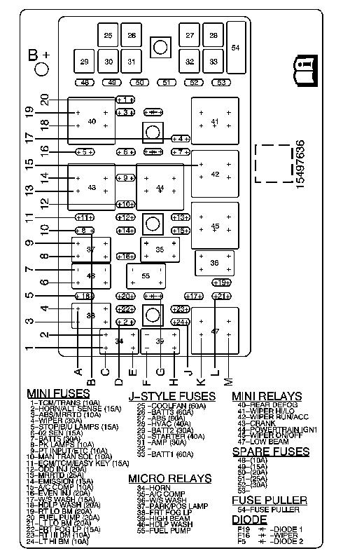
Anybody know where he got the pix above?
I'm looking for the same junction box lid schematic for a 2011 C6 convertible.
The number on my lid's schematic is 13686754-01 (upper right side of above schematic).
My lid's hinges were broken & since the lid is impossible to find, I got one for a 2006 - 2008 Cadillac XLR, Part # 19115455.
It's identical, but of course the schematic printed under the lid is incorrect.
Local sign shop says they can make me a correct stick on label, but they can't scan my broken lid as they need it to lay flat on their scanner.
I'm looking for the correct schematic as above for my car before I go butchering my broken lid in order for them to be able to lay it flat on their scanner.
Race Director
Joined: Sep 2009
Posts: 11,349
Likes: 2,443
From: Eastern
Anybody know where he got the pix above?
I'm looking for the same junction box lid schematic for a 2011 C6 convertible.
The number on my lid's schematic is 13686754-01 (upper right side of above schematic).
My lid's hinges were broken & since the lid is impossible to find, I got one for a 2006 - 2008 Cadillac XLR, Part # 19115455.
It's identical, but of course the schematic printed under the lid is incorrect.
Local sign shop says they can make me a correct stick on label, but they can't scan my broken lid as they need it to lay flat on their scanner.
I'm looking for the correct schematic as above for my car before I go butchering my broken lid in order for them to be able to lay it flat on their scanner.
I'm looking for the same junction box lid schematic for a 2011 C6 convertible.
The number on my lid's schematic is 13686754-01 (upper right side of above schematic).
My lid's hinges were broken & since the lid is impossible to find, I got one for a 2006 - 2008 Cadillac XLR, Part # 19115455.
It's identical, but of course the schematic printed under the lid is incorrect.
Local sign shop says they can make me a correct stick on label, but they can't scan my broken lid as they need it to lay flat on their scanner.
I'm looking for the correct schematic as above for my car before I go butchering my broken lid in order for them to be able to lay it flat on their scanner.
If you can take a pic, I have the program that will crop it for you and make it pretty for the scanner. Send me a PM if you want to do that and I'll send you my e-mail address.
Instructor
Joined: Feb 2020
Posts: 174
Likes: 40
From: Southern VA
Can you get a hi -res picture of the schematic from the cover? If so, then you can send it to a photo program, crop it, and then have the sign shop scan it for you.
If you can take a pic, I have the program that will crop it for you and make it pretty for the scanner. Send me a PM if you want to do that and I'll send you my e-mail address.
If you can take a pic, I have the program that will crop it for you and make it pretty for the scanner. Send me a PM if you want to do that and I'll send you my e-mail address.
Haven't found it yet, and my Haynes Repair Manual may have the relay / fuse layout, but no print is on the same page as the schematic.
I'll try taking a high resolution picture with my phone and playing with it in a few of my photo programs to see if I can come up with something he can use that will work.
Thanks for the offer.
Instructor
Joined: Feb 2020
Posts: 174
Likes: 40
From: Southern VA
Can you get a hi -res picture of the schematic from the cover? If so, then you can send it to a photo program, crop it, and then have the sign shop scan it for you.
If you can take a pic, I have the program that will crop it for you and make it pretty for the scanner. Send me a PM if you want to do that and I'll send you my e-mail address.
If you can take a pic, I have the program that will crop it for you and make it pretty for the scanner. Send me a PM if you want to do that and I'll send you my e-mail address.
Race Director
Joined: Sep 2009
Posts: 11,349
Likes: 2,443
From: Eastern
Good Luck. hope it works out. Those schematics are very hard to come by. They are not in the service manual. The owners manual has the schematic, but it is nor as found on the fuse box cover.
Race Director
Joined: Sep 2009
Posts: 11,349
Likes: 2,443
From: Eastern
