
[E38 ECM Pinout request] - Can anyone scan in a couple pictures for reference?
 07-09-2012, 02:10 PM
#1
Le Mans Master

Thread Starter
Member Since: May 2011
Location: Tampa FL (formerly Justinjor)
Posts: 5,022
Likes: 0
Received 14 Likes
on
9 Posts
Tech Contributor
St. Jude Donor '11-'12-'13-'14

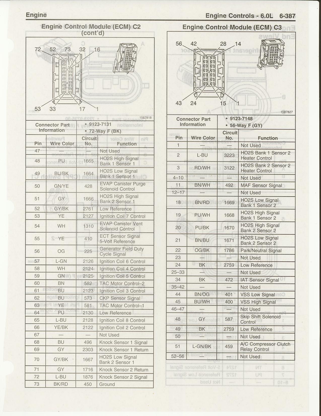
I'm looking to confirm some wiring and would like to find a pinout for the E38 computer. Does anyone have pictures somewhere they can link and/or upload? Searching the forum brought up dead ends. I'm looking for something like this for the E38.
Thanks in advance
Thanks in advance


 07-10-2012, 07:52 AM
#4
Le Mans Master
Thread Starter
Member Since: May 2011
Location: Tampa FL (formerly Justinjor)
Posts: 5,022
Likes: 0
Received 14 Likes
on
9 Posts
Tech Contributor
St. Jude Donor '11-'12-'13-'14
Email sent Ken, thank you.
Joe, thanks for the link. I've actually read that thread multiple times but will be going a different route for the setup. In fact, most of the work is done with a couple exceptions.
The IAT is a great sensor but doesn't respond as quickly as the ECT so that's the sensor I used to adjust the timing. In fact, I have a whole new timing map at the flip of a switch, it's actually pretty neat
07-10-2012, 08:19 AM
#5
Tech Contributor
Email sent Ken, thank you.
Joe, thanks for the link. I've actually read that thread multiple times but will be going a different route for the setup. In fact, most of the work is done with a couple exceptions.
The IAT is a great sensor but doesn't respond as quickly as the ECT so that's the sensor I used to adjust the timing. In fact, I have a whole new timing map at the flip of a switch, it's actually pretty neat
Joe, thanks for the link. I've actually read that thread multiple times but will be going a different route for the setup. In fact, most of the work is done with a couple exceptions.
The IAT is a great sensor but doesn't respond as quickly as the ECT so that's the sensor I used to adjust the timing. In fact, I have a whole new timing map at the flip of a switch, it's actually pretty neat
Post up what you're doing!
07-10-2012, 08:20 AM
#6
Le Mans Master
Thread Starter
Member Since: May 2011
Location: Tampa FL (formerly Justinjor)
Posts: 5,022
Likes: 0
Received 14 Likes
on
9 Posts
Tech Contributor
St. Jude Donor '11-'12-'13-'14
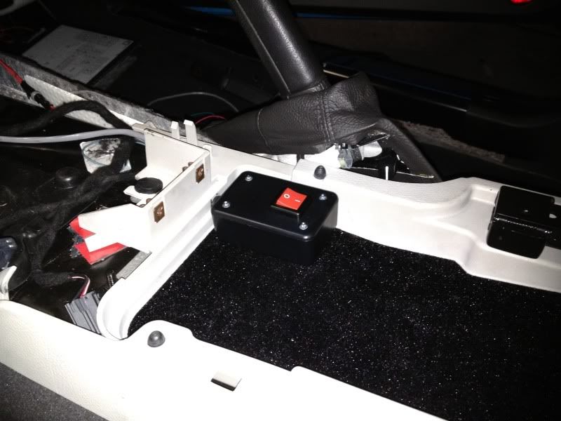
In time sir. I'll do a write-up/post-up when I get it all done. I don't have a lot of pictures since there's not a whole lot to see, but I'll post what I can.
Oh, and yes, I intercepted the ECT and wired in some resistance to put the temp around the 230* mark which is a temp I never see and isn't too hot where the computer goes into limp mode. Plus, I'll always know the timing is being pulled as I can just glance down at my temp sensor and see it hovering around that particular mark. Fool proof
Oh, and yes, I intercepted the ECT and wired in some resistance to put the temp around the 230* mark which is a temp I never see and isn't too hot where the computer goes into limp mode. Plus, I'll always know the timing is being pulled as I can just glance down at my temp sensor and see it hovering around that particular mark. Fool proof
07-10-2012, 08:25 AM
#7
Le Mans Master
Thread Starter
Member Since: May 2011
Location: Tampa FL (formerly Justinjor)
Posts: 5,022
Likes: 0
Received 14 Likes
on
9 Posts
Tech Contributor
St. Jude Donor '11-'12-'13-'14
Here's what it looks like. When the 'box' is switched off, the ECT functions normally. When I hit the switch, the temp goes to ~230 within a second
07-10-2012, 08:45 AM
#9
Former Vendor

Member Since: Apr 2012
Location: Deerfeild Beach FL
Posts: 178
Likes: 0
Received 0 Likes
on
0 Posts
07-10-2012, 01:11 PM
#12
Le Mans Master
Thread Starter
Member Since: May 2011
Location: Tampa FL (formerly Justinjor)
Posts: 5,022
Likes: 0
Received 14 Likes
on
9 Posts
Tech Contributor
St. Jude Donor '11-'12-'13-'14
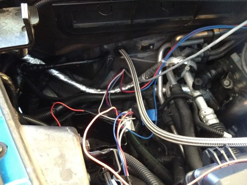
Thanks again Jay. I got one of the more delicate parts of the install done with your help. 
Birds nest turned into a clean install

Birds nest turned into a clean install
07-10-2012, 08:58 PM
#13
Safety Car

Member Since: Feb 2008
Location: TEXOMA
Posts: 3,712
Likes: 0
Received 3 Likes
on
3 Posts
St. Jude Donor '08-'09
Big NOS shot!
P.S. not 100% sure, but by manipulating the ECT, wouldn't that change the calculated IVT (Intake valve temp)? You might be ok, if you make the O/L tables all 1.0
-Carl
P.S. not 100% sure, but by manipulating the ECT, wouldn't that change the calculated IVT (Intake valve temp)? You might be ok, if you make the O/L tables all 1.0
-Carl
Last edited by carlrx7; 07-10-2012 at 09:01 PM.
07-10-2012, 10:19 PM
#14
Tech Contributor
Justin how about you. Scant months ago you didn't know Hp tuners from Fortran. Now look at you. Doing your own nitrous tune by tricking the ect parameter.
Way to go.
Way to go.
07-10-2012, 10:29 PM
#15
Le Mans Master
Thread Starter
Member Since: May 2011
Location: Tampa FL (formerly Justinjor)
Posts: 5,022
Likes: 0
Received 14 Likes
on
9 Posts
Tech Contributor
St. Jude Donor '11-'12-'13-'14
Carl. I'm not sure about that but I'll check. What "o/l" tables are you referring to?
 thanks Joe. It's amazing what you can learn from the internet.
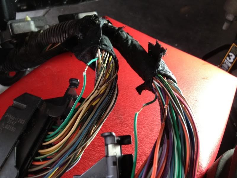
The progressive controller should be really impressive too. I tapped into the tach signal, VSS, wideband output, and TPS. All of those will allow me to keep things safe and progressively spray the nitrous based on rpm, vehicle speed, and throttle position. You can also have it auto correct to a given air fuel ratio as each of the solenoids are independently controlled. Its pretty trick stuff and I'm excited to experiment with it.
thanks Joe. It's amazing what you can learn from the internet. The progressive controller should be really impressive too. I tapped into the tach signal, VSS, wideband output, and TPS. All of those will allow me to keep things safe and progressively spray the nitrous based on rpm, vehicle speed, and throttle position. You can also have it auto correct to a given air fuel ratio as each of the solenoids are independently controlled. Its pretty trick stuff and I'm excited to experiment with it.
07-12-2012, 09:25 AM
#16
Le Mans Master
Thread Starter
Member Since: May 2011
Location: Tampa FL (formerly Justinjor)
Posts: 5,022
Likes: 0
Received 14 Likes
on
9 Posts
Tech Contributor
St. Jude Donor '11-'12-'13-'14
I wanted to give a quick update on this. . .
So I got everything all put back together and as soon as I turned the key on, I had 3 codes for the throttle body and the car wouldn't start. It would fire up, then display "REDUCED ENGINE POWER" and then stall. Considering I tapped into the TPS Sensor 1 wire in the ECU, I figured it had to be something with that.
Unplugging the nitrous controller box cleared all issues and the motor fired right up and idled perfectly, even with BR7 plugs installed. Further diagnosis lead me to the TPS wire that I tapped into being the cause of the issues and even FURTHER diagnosis showed me that in fact there are 2 TPS Signals in the ECU. Pin 63 and 65 are both TPS Signals and I originally tapped into 65(dark green). I fixed the original tap and then tapped into the 63 pin(purple) and boom, problem solved. The car fired right up with no codes, and the nitrous controller software showed the correct voltage and throttle blade angle.
I should be spraying this weekend(fingers crossed)

 06-02-2016, 05:58 PM
#18
Melting Slicks

Oil temperature wires (2) go to the gauge cluster. The oil level wire on the non dry sump engines goes from the gauge cluster to the level/temp sender on the side of the oil pan and then to the ECM.
Last edited by KENS80V; 06-02-2016 at 06:03 PM.
10-21-2021, 05:54 PM
#19
1st Gear


Member Since: Oct 2021
Posts: 1
Likes: 0
Received 0 Likes
on
0 Posts