P2068 vs p2066

Thread Starter
Cruising

Joined: May 2018
Posts: 12
Likes: 1
From: NC
Hi all, I have a 2007 corvette C6 that was receiving a P2068 code. I've watch many videos regarding replacing the sending unit in the passenger tank from YouTube. After building up the confidence I decided to do the work myself after the $1700.00 quote I received from the dealership. The question I have is I replaced the passenger sending unit, but now after driving the car I now receive a P2066 code. Has anyone heard of this? Do I need to go back and replace the driver side sending unit as well?
Thanks
RH
Thanks
RH
Last edited by UROB1; May 16, 2018 at 12:48 PM.
Pro


Joined: May 2014
Posts: 578
Likes: 39
From: Mount Airy MD
Which fuel level sensor did you install? There was a design change in 2007, and the earlier version might result in that code since the resistances are reversed. Please let us know what you discover!
FUEL SENDER OPERATION
The fuel level sender changes resistance in response to the fuel level. The engine control module (ECM) monitors the signal circuit of the primary fuel level sender and the secondary fuel level sender in order to determine the fuel level. When the fuel tank is full, the primary and the secondary fuel level sender resistance is low and the ECM senses a low signal voltage. When the fuel tank is empty, the primary and the secondary fuel level sender resistance is high and the ECM senses a high signal voltage. The ECM uses the signal circuit of the primary and secondary fuel level sender in order to calculate the percentage of remaining fuel in the tanks. The ECM sends the fuel level information via serial data circuit to the instrument panel cluster (IPC) for display in the fuel gage.
(The RH tank sender for 2007 and up should test to 247-253 Ohms from Half full to Empty and 38-41.5 Ohms at Full. 2005-06 are opposite of these readings.)
FUEL SYSTEM OPERATION
The fuel system is a returnless on-demand design. The fuel pressure regulator is a part of the fuel tank module, eliminating the need for a return pipe from the engine. A returnless fuel system reduces the internal temperature of the fuel tank by not returning hot fuel from the engine to the fuel tank. Reducing the internal temperature of the fuel tank results in lower evaporative emissions.
Two fuel tanks store the fuel supply. An electric turbine style fuel pump attaches to the fuel tank module inside the left fuel tank. The fuel pump supplies high pressure fuel through the fuel filter and the fuel feed pipe to the fuel injection system. The fuel pump provides fuel at a higher rate of flow than is needed by the fuel injection system. The fuel pump also supplies fuel to a Venturi pump located on the bottom of the left fuel tank module. The function of the Venturi pump is to fill the left fuel tank module reservoir. The primary fuel pressure regulator, a part of the left fuel tank module, maintains the correct fuel pressure to the fuel injection system. The left fuel tank module contains a reverse flow check valve. The check valve, the primary fuel pressure regulator, and the secondary fuel pressure regulator maintain fuel pressure in the fuel feed pipe and the fuel rail in order to prevent long cranking times.
The fuel pump also supplies a small amount of pressurized fuel through the auxiliary fuel feed pipe to the siphon jet pump inside the right fuel tank. The pressurized fuel creates a Venturi action inside the siphon jet pump. The Venturi action causes the fuel to be drawn out of the right fuel tank.
The fuel transfers from the right fuel tank to the left fuel tank through the auxiliary fuel return pipe. The auxiliary fuel return pipe inside the left fuel tank contains an anti-siphon hole in order to prevent fuel from siphoning from the left fuel tank into the right fuel tank. Both the auxiliary fuel feed pipe and the auxiliary fuel return pipe are located inside the convoluted stainless steel crossover hose.
The right fuel tank module contains a secondary fuel pressure regulator. The secondary fuel pressure regulator has a lower set point than the primary regulator in order to allow fuel to flow to the siphon jet pump on the right fuel tank module. When the engine is shut off, the pressure in the feed pipes immediately drops to the secondary regulator set point. This prevents the siphon jet pump from operating and in turn prevents the equalization of the left and right fuel tanks. The secondary fuel pressure regulator maintains fuel pressure in the auxiliary fuel feed pipe which reduces the time to prime the siphon jet pump. The pressurization also reduces fuel vaporization and boiling in the auxiliary fuel feed pipe.
#PIC4765A: Erratic Fuel Gauge Operation DTCs P2066 And/Or P2636 - keywords cluster empty gage inaccurate inoperative instrument IPC needle panel dender tank - (Feb 21, 2008)
Subject: Erratic Fuel Gauge Operation DTCs P2066 and/or P2636
Models: 2007-2008 Chevrolet Corvette
--------------------------------------------------------------------------------
This PI was superseded to update the information that step 5 is always performed. Please discard PIC4765.
--------------------------------------------------------------------------------
The following diagnosis might be helpful if the vehicle exhibits the symptom(s) described in this PI.
Condition/Concern:
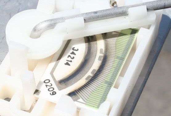
Some customers may comment that the Fuel gauge goes to empty when the fuel level is greater than what is shown on the gauge and DTCs P2066 and P2636 are present. When these codes are present the Fuel Level Low message should be displayed on the DIC. This could be caused if the ECM does not receive the expected voltage signal to indicate that the fuel transfer is properly occurring. If this condition exists for 30 minutes both of these DTCs will be set. The fuel level sensor card may have slight discoloration possibly caused by fuel contamination which can affect the level sensor output. The fuel level sensor diagnostics are sensitive to this issue.
Recommendation/Instructions:
Verify that P2066 and P2636 DTC are set.
Confirm fuel rail pressure with the fuel pump on is 58-62 psi. If the pressure is not within this range, follow eSI Service Procedures to correct the issue and then proceed to Step 5.
Confirm proper jet pump transfer by checking and recording the fuel level sensor voltages using a Tech2. This must be performed with less than 3/4 tank of fuel. If required, remove sufficient fuel from the Schrader valve on the fuel rail. Follow all safety procedures as outlined in SI. Clear the DTCs to get a reading on the fuel gage. If the secondary (passenger side) sender is less than 2.2 volts and the primary (driver side) is more than .86 volts, the secondary (passenger side) level sensor and the module (includes the jet pump) should be replaced. Prior to replacing fuel hardware confirm all wiring connections are fully seated and harnesses are properly routed. After replacing the level sensor and module move to step 5.
If the jet transfer pump is operating properly the fuel sender card may be contaminated. This could cause an incorrect voltage signal to be sent to the ECM. Customers should be advised to correct a contamination issue by adding one bottle of GM Fuel System Treatment PLUS (part number 88861011) to the fuel system on their next fuel fill. Note; the fuel level must be below � tank when the fuel treatment is added. The treatment rate is 1 oz. per gallon of fuel (Using one 20 oz bottle to the fuel system is acceptable). To clean a severely contaminated fuel level sensor, it is permissible to treat the fuel system on two consecutive tanks.
Note: Back to back treatment is only permitted once in the life of the vehicle. After the initial treatment, customers should be advised to add one bottle of GM Fuel System Treatment PLUS to the fuel tank at every oil change, however, not more frequently than once every 3000 miles. Proceed to step 5
A revised ECM calibration 12624797 is available through TIS2WEB under the fuel system heading. To reflash the ECM please use labor operation L1199 @ .2 hours. If the vehicle continues to have the concern after the calibration has been updated it is possible there is an intermittent jet transfer or an intermittent stuck float arm issue. Poor jet transfer could be due to an intermittent clog in the jet pump or a kinked transfer line in the either fuel tank.
Fuel contamination is discussed in service publication 05-00-89-078B and Top Tier Fuel is discussed in publication 05-06-04-022D. These documents should be provided to customers if they have questions regarding fuel quality. E85 fuel requirements are reviewed in publications 06-06-04-035A and 05-06-04-035C. E85 must not be used in Corvettes.
Subject: Erratic Fuel Gauge Operation DTCs P2066 and/or P2636
Models: 2007-2008 Chevrolet Corvette
--------------------------------------------------------------------------------
This PI was superseded to update the information that step 5 is always performed. Please discard PIC4765.
--------------------------------------------------------------------------------
The following diagnosis might be helpful if the vehicle exhibits the symptom(s) described in this PI.
Condition/Concern:
Some customers may comment that the Fuel gauge goes to empty when the fuel level is greater than what is shown on the gauge and DTCs P2066 and P2636 are present. When these codes are present the Fuel Level Low message should be displayed on the DIC. This could be caused if the ECM does not receive the expected voltage signal to indicate that the fuel transfer is properly occurring. If this condition exists for 30 minutes both of these DTCs will be set. The fuel level sensor card may have slight discoloration possibly caused by fuel contamination which can affect the level sensor output. The fuel level sensor diagnostics are sensitive to this issue.
Recommendation/Instructions:
Verify that P2066 and P2636 DTC are set.
Confirm fuel rail pressure with the fuel pump on is 58-62 psi. If the pressure is not within this range, follow eSI Service Procedures to correct the issue and then proceed to Step 5.
Confirm proper jet pump transfer by checking and recording the fuel level sensor voltages using a Tech2. This must be performed with less than 3/4 tank of fuel. If required, remove sufficient fuel from the Schrader valve on the fuel rail. Follow all safety procedures as outlined in SI. Clear the DTCs to get a reading on the fuel gage. If the secondary (passenger side) sender is less than 2.2 volts and the primary (driver side) is more than .86 volts, the secondary (passenger side) level sensor and the module (includes the jet pump) should be replaced. Prior to replacing fuel hardware confirm all wiring connections are fully seated and harnesses are properly routed. After replacing the level sensor and module move to step 5.
If the jet transfer pump is operating properly the fuel sender card may be contaminated. This could cause an incorrect voltage signal to be sent to the ECM. Customers should be advised to correct a contamination issue by adding one bottle of GM Fuel System Treatment PLUS (part number 88861011) to the fuel system on their next fuel fill. Note; the fuel level must be below � tank when the fuel treatment is added. The treatment rate is 1 oz. per gallon of fuel (Using one 20 oz bottle to the fuel system is acceptable). To clean a severely contaminated fuel level sensor, it is permissible to treat the fuel system on two consecutive tanks.
Note: Back to back treatment is only permitted once in the life of the vehicle. After the initial treatment, customers should be advised to add one bottle of GM Fuel System Treatment PLUS to the fuel tank at every oil change, however, not more frequently than once every 3000 miles. Proceed to step 5
A revised ECM calibration 12624797 is available through TIS2WEB under the fuel system heading. To reflash the ECM please use labor operation L1199 @ .2 hours. If the vehicle continues to have the concern after the calibration has been updated it is possible there is an intermittent jet transfer or an intermittent stuck float arm issue. Poor jet transfer could be due to an intermittent clog in the jet pump or a kinked transfer line in the either fuel tank.
Fuel contamination is discussed in service publication 05-00-89-078B and Top Tier Fuel is discussed in publication 05-06-04-022D. These documents should be provided to customers if they have questions regarding fuel quality. E85 fuel requirements are reviewed in publications 06-06-04-035A and 05-06-04-035C. E85 must not be used in Corvettes.
Race Director

Joined: Jan 2006
Posts: 18,396
Likes: 169
I am having fuel gauge problems ever since a new complete fuel pump canister was installed in my 2005. The gauge is stuck on full and doesn�t move with the change in fuel level. Then, it will throw the 2066 code, a �Service Fuel System� in th DIC and the gauge pegs at empty.
From reading the previous post, I�m beginng tp suspect a 2007+ fuel pump canister was installed?
Any thoughts?
Thanks.
From reading the previous post, I�m beginng tp suspect a 2007+ fuel pump canister was installed?
Any thoughts?
Thanks.

Race Director


Joined: Dec 2013
Posts: 12,502
Likes: 3,631
I am having fuel gauge problems ever since a new complete fuel pump canister was installed in my 2005. The gauge is stuck on full and doesn�t move with the change in fuel level. Then, it will throw the 2066 code, a �Service Fuel System� in th DIC and the gauge pegs at empty.
From reading the previous post, I�m beginng tp suspect a 2007+ fuel pump canister was installed?
Any thoughts?
Thanks.
From reading the previous post, I�m beginng tp suspect a 2007+ fuel pump canister was installed?
Any thoughts?
Thanks.