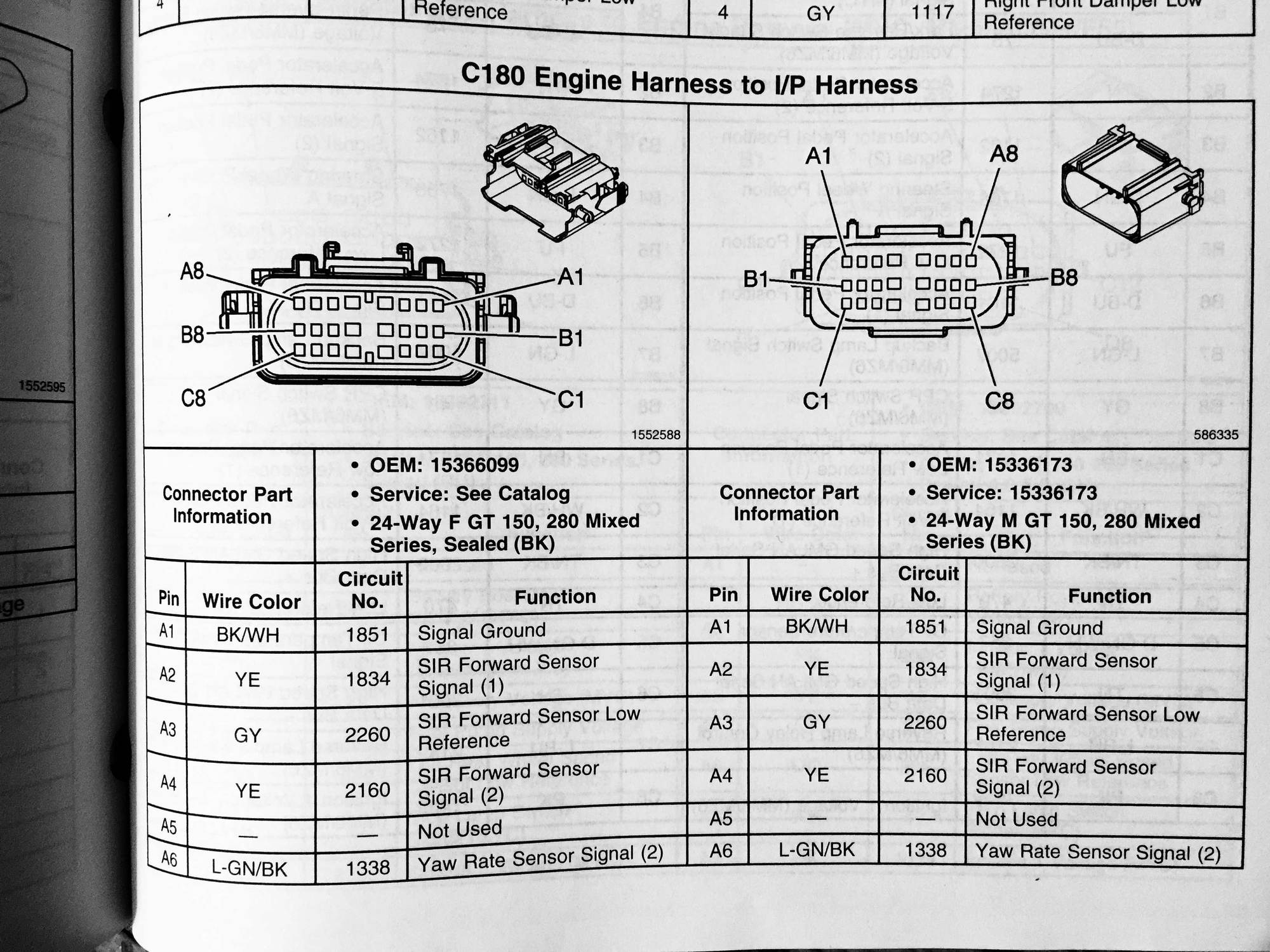
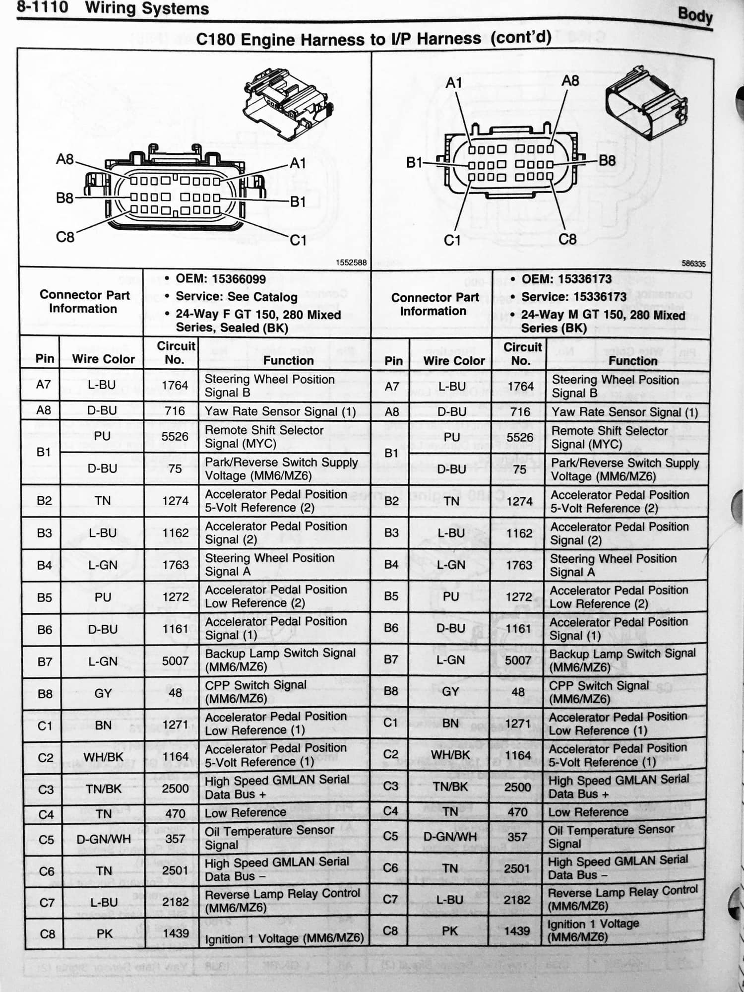
C180 underhood connector pinout
#1
Heel & Toe


Thread Starter
I need a schematic or pinout description for the C180 connector that goes between the cockpit harness and the engine compartment. I have already found schematics and diagrams for the C1, C2, C3 connectors as well as the X1 and X2 ECM connectors.
I am trying to set up a remote engine and driveline wiring system with the ECM, Accelerator pedal, fuse/relay box, etc. for the project. I have already figured out the six-wire accelerator pedal wiring to the ECM, but haven't traced out the other wires from this plug yet.
Any information is helpful. Thanks
#3
Heel & Toe


Thread Starter
Thanks, TorqueTube. That is a big help, and I will add it to my "library". I purchased a service manual online which is 8166 pages long and has over 100 pages of electrical schematics, but doesn't have this table.
An update, I am new to this system. I am trying to communicate with an ECM from a 2011 Corvette on a bench. This OBD2 uses the following pins:
Pin 2 - Purple wire - Serial Data (original wiring sends this to the JX205 and MX208 harnesses adjacent to steering wheel
Pin 4 - Black wire - Ground wire connection at left door pillar
Pin 5 - Black/white wire - Ground wire at frame next to battery
Pin 6 - Tan/black wire - High-speed GMLAN serial data (+) at body control module
Pin 14 - Tan wire - High-speed GMLAN serial data (-) at body control module
Pin 16 - Red/white wire - +12 Volts hot
Since I am trying a bench setup, the High-speed serial data wires have been soldered from the OBD2 plug directly to the tan wire at X1 ECM plug at pin 27 and the tan/black wire at X1 ECM plug at pin 28. I don't know the location for the purple wire for serial data. I have not connected wire #2 to anything, since I can't find a pin on the ECM to accept it. I do get a brief attempt of communicating between MPVI2 and the ECM. Then, this message appears:
""unable to detect the vehicles diagnostics protocol. It's possible that this vehicle isn't supported yet by VCM Scanner. E-mail support@hptuners.com so that we may add it. Another possibility is that all the controllers (VCM's) in the vehicle are not responding for various reasons."
This car has multiple Vehicle Control Modules in its structure, but I am only using the Engine Control Module at my bench test. I hope I don't have to also hook up the Body Control Module.
I know the scanner works, because I plugged into my Denali truck OBD2 and was instantly communicating. So, what is necessary for the bench setup that I am missing.
#4
Heel & Toe


Thread Starter
Got the problem resolved. I had a break in the black/tan wire. I tinned the wire ends, soldered, added a short piece of shrink tube, and all is well. Hope to have the LS3 running on my test bench as soon as I get back in town for a couple days.


