


Right Fuel Tank Sender Bypass

Thread Starter
Intermediate


Joined: Nov 2007
Posts: 39
Likes: 2
I am posting this to 1. Apologize to the member “torquetube” for my undignified and way over the top response to torquetube’s attempt to describe how the fuel sensor system works on a C6 Corvette, and 2. To. Retract my previous description on how the fuel sensor works on the C6 Corvette.
My previous incorrect description on how the fuel level system operated was based on several faulty assumptions.
First, I incorrectly assumed that the C6 fuel sensor used an “in-tank” three-wire potentiometer that worked as a voltage divider and that the PCM (or ECM) would measure the voltage drop across one half of the “in-tank” potentiometer (voltage divider) to calculate the fuel level. I have now corrected that error and can say that torquetube, and several other members were correct and that the in tank sensor is a two wire variable resistor, and there is a remotely located resistor, probably in the PCM, that along with the in-tank sensor, works as a voltage divider to supply the information on fuel level to the PCM.
My faulty assumption was based on my experience with my 1972 Chevy C20 truck (simple as it gets), and my 2002 Suburban (uses a PCM), both of which use a three wire in-tank variable resistor fuel level sensor. (Recently I removed the fuel level sensor to repair the third wire on the Suburban fuel level sensor to repair the sensor after it quit working). Also, when I bypassed the fuel level sensor on the right-hand tank of my 2006 Corvette, the connector had three wires, and I was able to read resistance between all three pins of the in-tank variable resistor. I incorrectly assumed that the sensor was a three-wire variable resistor that worked as a voltage divider as in my C20 and Suburban. I now believe that the reason I could read resistance through all three wires is because the two-wire variable resistor is damaged in such a fashion that the two wires it shorts out to the ground wire. I can only assume that is the reason since I have not removed the sensor from the tank.
Secondly, while my previously incorrect description was based on a three-wire variable resistor in the tank, torquetube, and other members, said that they only had a 2-wire variable resistor in the tank. Torquetube also insisted that there were only two wires going to the right-hand tank even though he attached a wiring diagram that clearly showed there were three wires going to the right-hand tank. As an electronics technician for 20 years in the military, and then afterwards, I have only seen a voltage divider that varied voltage. Never one that used a two-wire resistor to vary current and voltage. I have learned something new. In the end, torquetube, and others, were correct, and the fuel level sensor in my 2006 and a 2007 Vetter is a two-wire variable resistor voltage divider.
As the online discussion went on, members also started to refer to a “pull down” resistor. I incorrectly assumed that the “pull down” resistor was the second half of the three-wire variable resistor. In his last response, torquetube made a new reference to the “pull down” resistor and said that it was located on the “5 volt PCM rail.”
I then decided do the calculations to determine if torquetube, and the other members that referred to some “pull down” resistor were correct. I had doubt because I have never seen such a voltage divider setup in electronics where the circuit varies the output voltage of a voltage divider by varying the current through a circuit to vary the voltage. (I have learned something new.) I wanted to see if I could create such a voltage divider using a fixed value resistor (the so-called pull-down resistor) and a two-wire variable resistor and if the circuit that would satisfy the resistance and voltage output measurement provided by GM for the 2006 and the 2007 Vette. I also calculated the output voltages using the three-wire variable resistor I incorrectly assumed was in the tank. Whereas before I based my position on the output voltage when the tank was empty, this time I calculated the output voltages through the entire range of the fuel sender-from full to empty.
My calculations using the three-wire variable resistor in the tank were close to the GM voltage measurements, but across the full range of fuel levels the voltages were all off by 10-15%. I made the same calculations using remotely located and fixed 240 ohm “pull down” resistor and a two-wire in-tank variable resistor. Using this method, across the full range of fuel levels, the output voltages matched those listed by GM with less than a 0.1% error. Clearly the mathematics show that GM designed the fuel level sensor’s voltage divider circuit using a fixed resistor and a two-wire variable resistor.
I therefore do believe that torquetube and the others that said the fuel level sensor in the tank is a two wire variable resistor were correct. I also believe that the ground wire that was on the wiring diagram provided by torquetube is a safety feature to prevent any potential arching in the fuel tank that could be caused by the varying the current through the fuel level sensor. Also, I believe that you can bypass the sensor by simply installing either a 64-ohm resistor in the 2005-06 Vette, or a 250 ohm resistor in the 2007 Vette, with one lead connected to the black wire and the other lead connected to the light blue wire.
Last edited by peterpeter211; Mar 31, 2019 at 09:35 PM. Reason: Updated information
Thread Starter
Intermediate
Joined: Nov 2007
Posts: 39
Likes: 2
I don't have an HP tuner (not even sure what it is), but if I did and it worked I would've used that. Still for less than a dollar, this will work until I have to change the fuel pump in the left tank.
Last edited by peterpeter211; Feb 27, 2019 at 11:58 PM.
Corvette Stories
The Best of Corvette for Corvette Enthusiasts

Top 10 Most Expensive Corvettes Ever Sold on Bring A Trailer
Brett Foote
10 Things Every Corvette Owner Needs (2026 Edition)
Michael S. Palmer
8 Most "Only Corvette Owners Understand" Quirks and Problems
Pouria Savadkouei
10 Reasons the C6 Z06 is Still A Performance Benchmark After 20 Years
Joe Kucinski
How Much Horsepower Every Corvette Engine "LOST" in 1972
Joe Kucinski
Top 10 DOs and DON'Ts for Protecting Your Convertible Top!
Michael S. Palmer
Top 10 Most Explosive Corvettes Ever Made: Power-to-Weight Ratio Ranked!
Joe Kucinski
150 hp to 1,250 hp: Every Corvette Generation Compared by the Specs That Matter
Joe Kucinski
8 Coolest Corvette Pace Cars (and Replicas) of All Time
Verdad Gallardo

Le Mans Master


Joined: Dec 2004
Posts: 5,493
Likes: 809
From: West coast CA
I then attached one end of the 100 ohm resistor to the 5 volt line on the connector, the junction with the 100 and 400 ohm resistor to the reference voltage wire, and the end of the 400 ohm resistor to the ground line on the connector. The PCM now reads 1 volt, and has 0.01 amps flowing in the circuit.
Le Mans Master
Joined: Dec 2004
Posts: 5,493
Likes: 809
From: West coast CA
My 2006 Vette has 3 wires, as I know 2007s do, and I believe all C6 Vettes do. One is the 5 volt reference from the PCM (light blue on mine) one black wire the PCM uses to measure the voltage drop as the fuel level changes, and a black and white wire that connects to ground.
The fuel level sensor is a three wire potentiometer, also know as a voltage divider because the voltage changes as the fuel level changes. (In contrast a two wire variable resistor, also called a reostat, changes circuit current as the resistance changes. Not used in Corvette fuel system though).
5 volts flows through one side of voltage divider(light blue eye), the voltage drop is measured by the PCM(black wire), and then to ground (black and white wire) through the other resistor in the voltage divider.
If you use one resistor, that resistor will drop all 5 volts and then you get a high voltage DTC
The blue wire is pulled up to ~5V through a resistor inside the engine control module. This is the fuel level signal. The black wire is a low-impedance ground reference. There is no third wire involved in the level sensor circuit.
The voltage divider is created by the internal pull-up and the level sensor variable resistor.
Consider a textbook voltage divider:
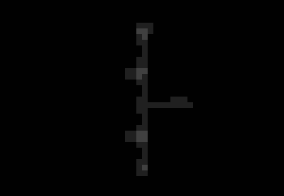
Here is the same circuit with labels applied:

Le Mans Master
Joined: Dec 2004
Posts: 5,493
Likes: 809
From: West coast CA
Maybe a counting lesson will help. Thanks for attaching your picture which proves my point. Using your picture:
1. Is called VIN (voltage in) on your picture, this is the 5 volt input
2. Is called VOUT (voltage out) on your picture, This is the voltage drop caused by one half of the potentiometer used as the fuel level sensor (attached to the float) used by the PCM to measure fuel level. This voltage changes as fuel level chances.
3. Is the ground. It is the second half of the potentiometer.
1,2,3. Yep three wires. Typical voltage divider. It is very advanced electronics so no way anyone can expect you could to understand these complicated concepts.
And just in case math isn't your strength, and I can see it isn't, I've attached a wiring diagram of the sensor so you can count the wires.
One day when you get a Vette you can look at the connector and count 1,2 and 3 wires
Look at my picture again. The red box with the dashed outline is the ECU. Everything inside that box is inside the ECU.

I can see why based on your drawing alone you might think the level sensor is a potentiometer, but it is not. Only two wires go to the sensor. It is a two-terminal variable resistor. Terminal 1 (LT BLU) is the pulled-up signal wire from the ECU (VOUT in the drawing above), and terminal 4 (BLK) is the low-impedance low reference (ground symbol in the drawing above; in practice it is a dedicated wire at ground potential, not chassis ground).
Let's look at the actual schematic from the factory service manual:

Note that both level senders are two-wire circuits with a common low reference.
Note the pull-up resistors inside the ECU, as I already mentioned.
If you still don't believe me, let's look at the actual physical sensors. I removed these myself from my 2006 Corvette:

Right-side level sensor. A closer view:

Two undifferentiated wires. A variable resistor. Hook them up either way; it doesn't matter.
Here's the left one:

Same drill:

This is a very typical level sensor design used throughout the industry.
I've attached a PDF from Bourns that restates everything I've already mentioned.
Le Mans Master
Joined: Dec 2004
Posts: 5,493
Likes: 809
From: West coast CA
So your sensor has two wires. That is the VOUT side of the circuit. The voltage divider does not require "a separate" ground wire. Often circuits are grounded to the housing (typically a screw through the circuit board with the screw touching the second half of the potentiometer and the housing), which is then grounded to the car chassis via a grounding strap or separate wire. If there are two wires, then you ground the end of the second resistor to the cars chassis. This is called a floating ground (no pun intended).
There is no external divider. The divider is formed by the pull-up inside in the ECM ("R1") and the level sensor ("R2"). This is a super common method of resistive sensor measurement.

VIN is the +5V supply rail inside the ECM. R1 is the internal pull-up. It should be about 240Ω. VOUT is the light blue wire. R2 is the variable resistor inside the gas tank. The low reference can be thought of as a dedicated ground.
The VOUT voltage is measured by the ECM's A/D converter to determine the fuel level.
Recall that VOUT = VIN x (R2 / (R1 + R2)).
When R2 is 250Ω (full tank on early C6s), what is VOUT? VOUT = 5 x (250 / (240 + 250)) = 2.55V.
When R2 is 40Ω (empty tank on early C6s), what is VOUT? VOUT = 5 x (40 / (240 + 40)) = 0.71V.
Those voltages should look familiar. They correspond to GM's values from schpenxel's table posted earlier in this thread:

Note that the resistance range was reversed for the 2007 model year, but this doesn't change the math.
Le Mans Master
Joined: Dec 2004
Posts: 5,493
Likes: 809
From: West coast CA
Not only do my numbers match, but at the risk of exploding whatever brain that you have, I have provided proper wattage for the resistors. Also while not in here, I have confirmed that my circuit has the proper transistor voltage and current biases. But I'm only asking you for ohms law. You can save your time if you don't believe in ohms law or believe the planet is flat.
As a betting guy, I'd bet a large sum money that you just send another BS response. I only provide this detailed response so that those with the ability to understand electronics and can use simple algebra will benefit. I can't imagine you getting any benefit since you've consistently struggled with counting to three.
As a betting guy, I'd bet a large sum money that you just send another BS response. I only provide this detailed response so that those with the ability to understand electronics and can use simple algebra will benefit. I can't imagine you getting any benefit since you've consistently struggled with counting to three.
For the benefit of other forum members who may have been misled by the misinformation peterpeter211 is spreading:
The C6 fuel level sensors are not 3-terminal potentiometers/voltage dividers. They are 2-terminal variable resistors.
A cursory examination of the sensors themselves will reveal this to be the case. So will a reading of the circuit description. So will experience with most modern automotive systems. There is no wiper terminal. The sensor provides a single resistance value. Persons insisting otherwise against all evidence are embarrassing themselves.
The larger circuit of which the sensor is a part forms a voltage divider in combination with the (blue) fuel level signal wire which is pulled-up to +5V through a resistor inside the ECM.
Race Director


Joined: May 2004
Posts: 16,667
Likes: 1,209
From: Raleigh, NC
St. Jude Donor '15
I honestly don’t know who is trolling who at this point.
The sender is 2 wires and the resistor shown in the diagram is in the ECM. That is all correct. Take it or leave it.
The sender is 2 wires and the resistor shown in the diagram is in the ECM. That is all correct. Take it or leave it.