When you click on links to various merchants on this site and make a purchase, this can result in this site earning a commission. Affiliate programs and affiliations include, but are not limited to, the eBay Partner Network.
C6 Driver's Seat Track Sliding / Rocking Repair DIY Info
C6 Driver seat removal due to sliding backward movement feeling on acceleration caused by worn rubber 'bushing/spacer' and it was squeaking loudly when moving back and forth due to dry, unlubricated rail/screw assemblies.
Rocking seats are a different issue commonly caused by broken plastic Clevis. The Clevis parts are shown below, but only for lubricating in my case, after the rails/tracks info.
This is posted as DIY "... it worked for me" and is not an absolute best/only method. Others will comment adding additions and corrections on my errors, easier, etc. If I've made any errors I will edit and give thanks noting member's username for the correction in the post.
Every item/step may be different for early model year and seat options (# of electrical connectors, etc.)
I am posting since most previous threads link to off-site, or those on site no longer had active photos displaying, etc., as well as, specific personal notes that that are not posted elsewhere and pics uploaded here.
Pre-Notes:
IMPORTANT: If you have seat airbags wait (I use 30 minutes) from the time you disconnect the battery until the time you disconnect the electrical connectors under the seat. This allows time so you DO NOT set off the Seat Side Airbags by disconnecting them prematurely and setting them off (deploying) due loss of monitored/active electrical.
Open hood, hatch & driver's door with window down. You'll be disconnecting the battery.
Remove and stow targa top (retract vert). Needed for access to lift up and maneuver the seat out.
Have a prepared and covered surface area to take the seat to set it down on. I used a folding table and towel.
Highly recommend doing one rail assembly at a time to not mix up L&R track pats. There are Left and Right hand threaded drive screw assemblies/parts.
When tracks reassembled they must match alignment & measurements as when you began. This is done by using tape, whiteout, etc. as alignment markings along with measurements.
The main concern when reassembled is the tracks must be the same measurements on each side. They cannot be different, or the seat may bind/jam/etc causing motor/mechanical/electrical damages.
Battery Notes:
1 - Once you disconnect it, you cannot move seat(s). I removed the front nuts first, move seat all the forward and then removed the rear mounting nuts. Then disconnected battery with seat in all the way forward position.
2 - One you reconnect it, if you have the Auto-Memory Seat Recall option (Owner's Manual 5-57) seat may automatically fully retract. Do not leave anything behind the seat that can impede travel.
Tools:
* Socket wrench (3/8 utilized) & 6" extension & 10mm & 15mm Deep - for removing seat & components
* 10mm Wrench (Open, box, or ratcheting) - for screw drive assy from inner rail
* Towel/Fender Cover/etc to cover threshold/sill and protect from scratching
* Flat blade screwdriver - for removing tabs in front plastic track covers
* Blue Loctite - dab on screws when reassembled
* Tape (painters/masking/duct/etc) - for marking track alignment when separated.
* Marine grade grease/lubricant recommended - for track grooves and flexible shaft ends
* E12 Socket [Female Torx] (aka Vice-Grips if applicable)
* Repair kit/method of your choice
Left Side (Power Control side & where lap belt attaches)
#1 - Remove (2) Seat Mount Plastic Covers from front rails by removing the push-pull pins.
#2 - Remove (2) front 15mm nuts w/deep socket. Stow away and not side specific.
#3 - Move seat fully forward and remove the (2) 15mm nuts w/deep socket
#4 - Disconnect battery negative (black) cable and safely secure. Cover threshold with towel.
#5 - Remove seat belt nut w/15mm deep. (Put the nut back on the screw stud to not loose and remember its location)
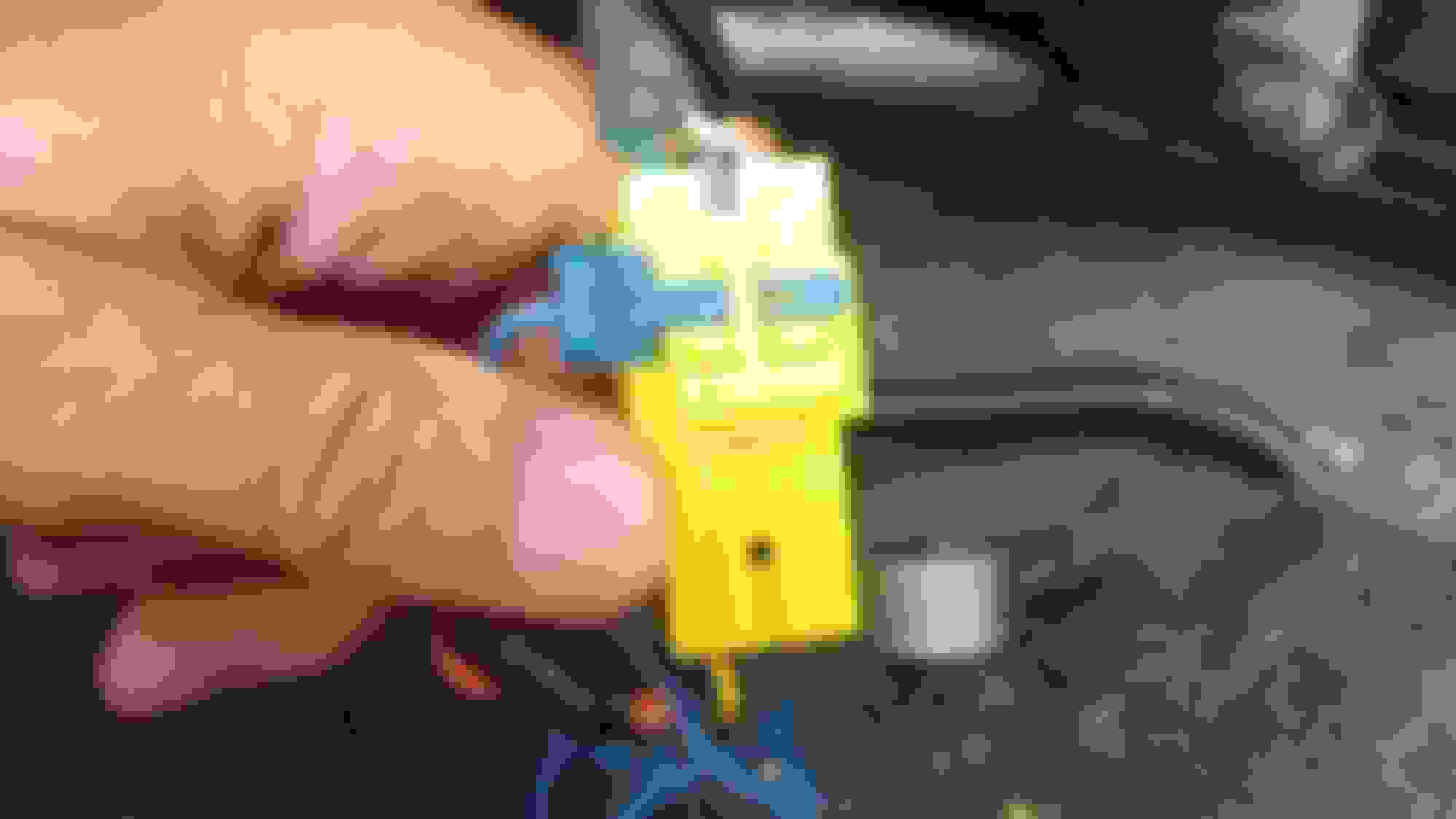
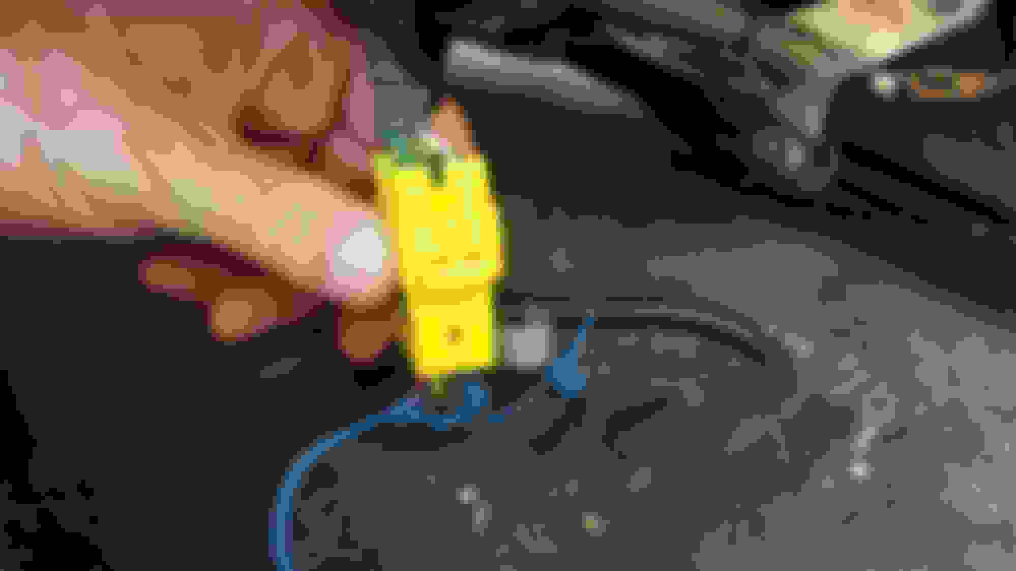
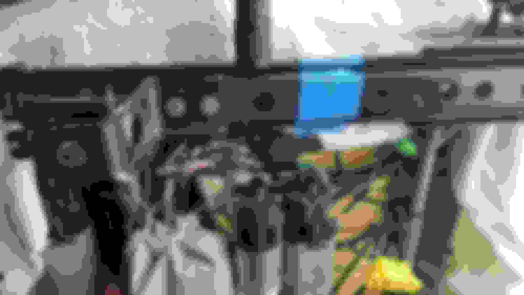
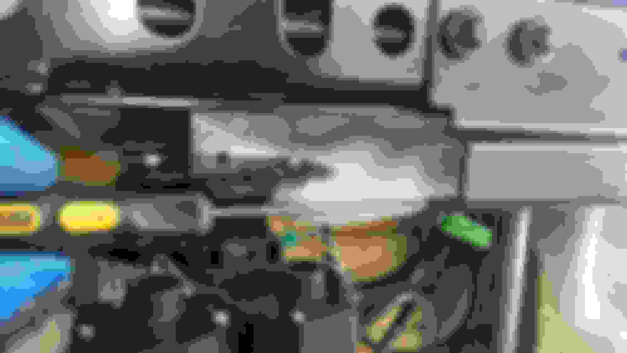
#6 - Lift seat and I had 3 electrical connectors: Solid Black | Yellow | Black w/Purple clamp
#7 - Separate the Yellow by removing the blue pin, then lifting up on the tab, pulling apart to disconnect. Last pic is of side view Blue Pin Secured Blue Pin Removed Connector separated
#8 - Black with Purple: rotate the purple clamp
#9 - Solid Black: Gently lift up on the tab on the bottom half in the pic and disconnect
#10 - Lift up and carefully maneuver seat out taking it to your prepared work area.
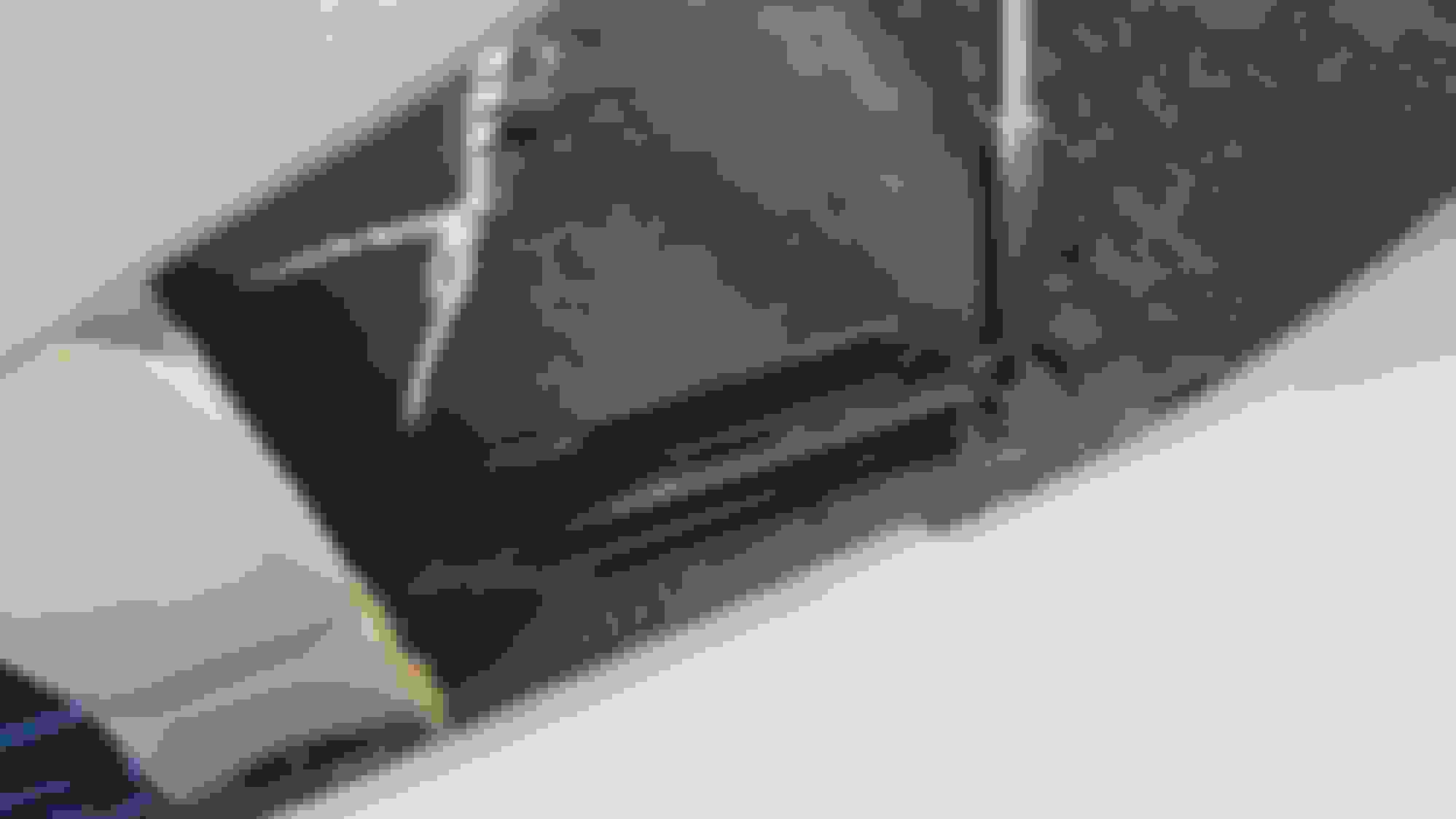
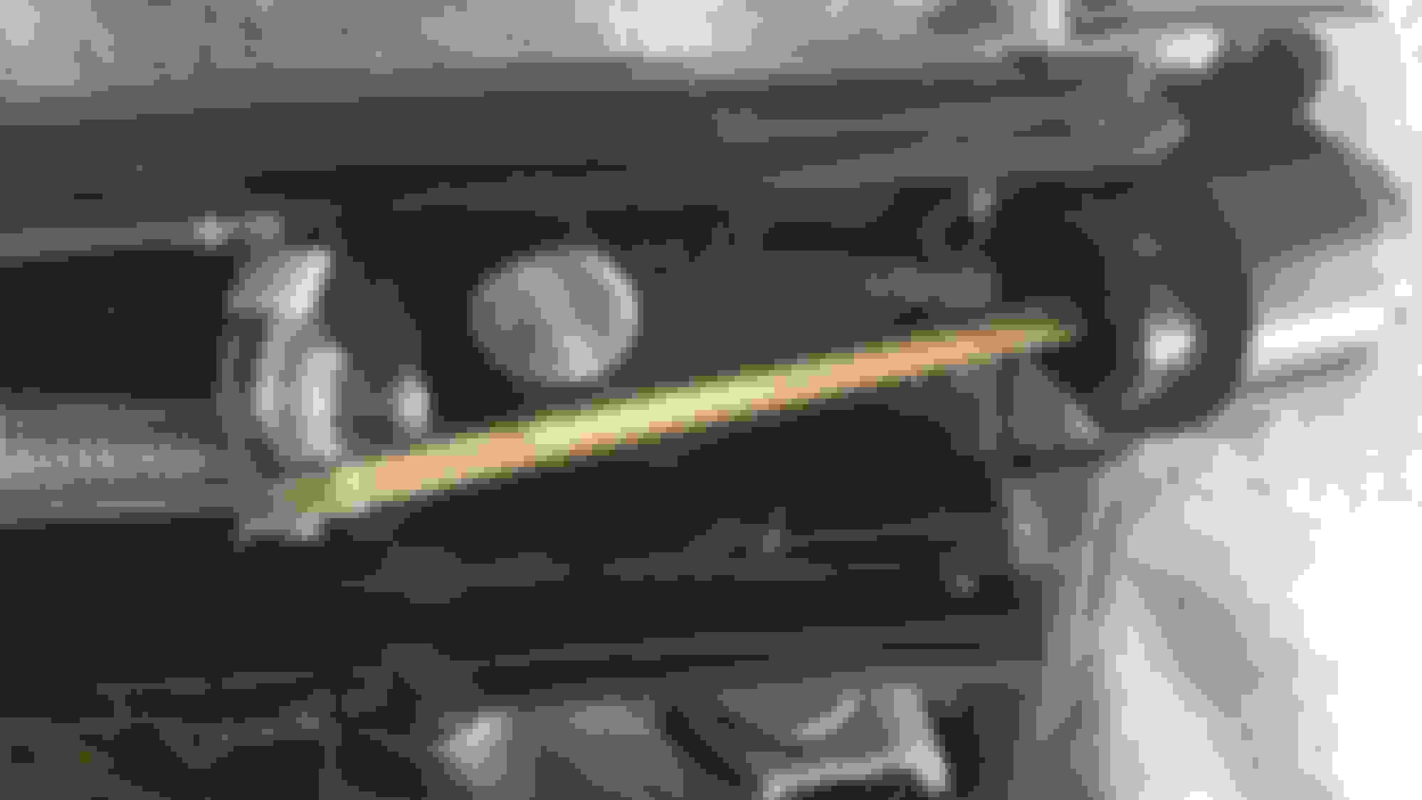
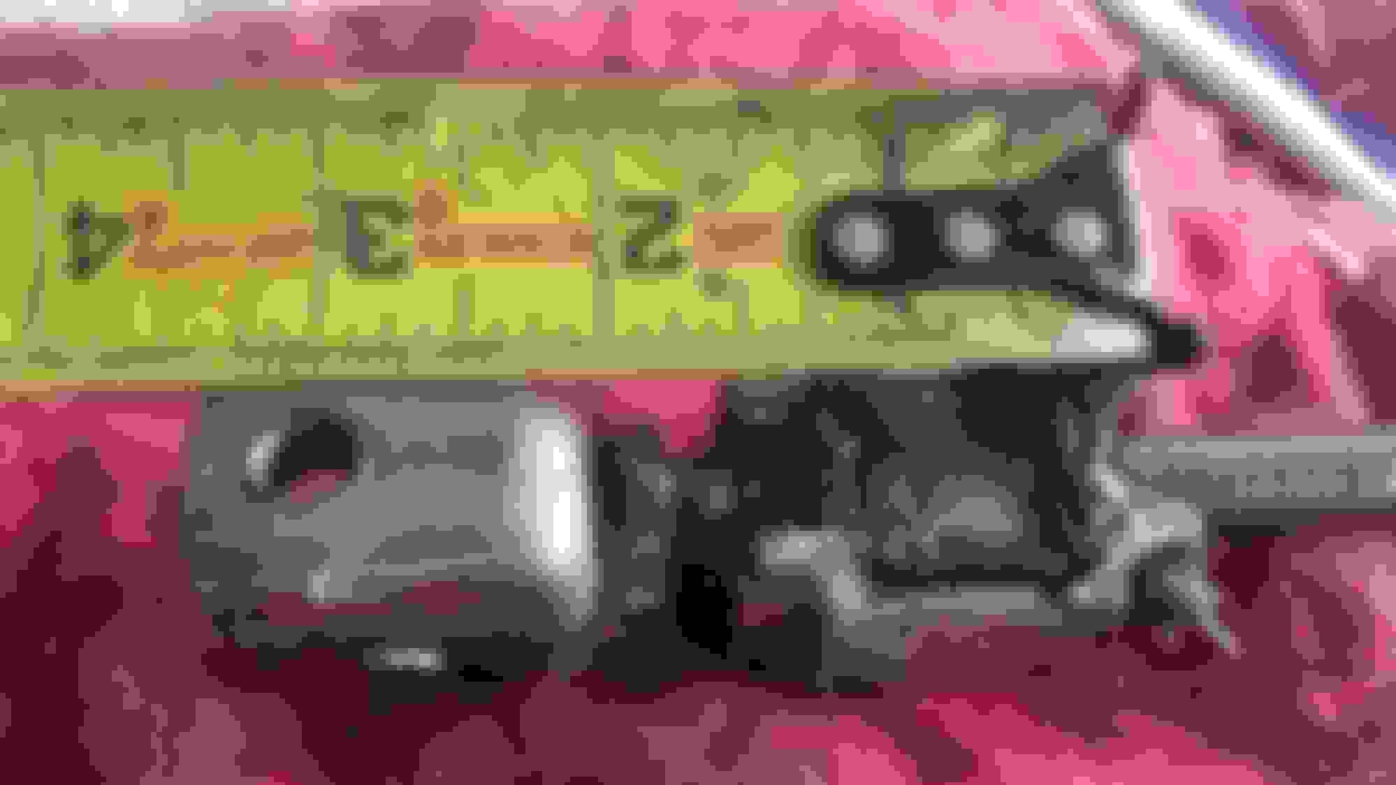
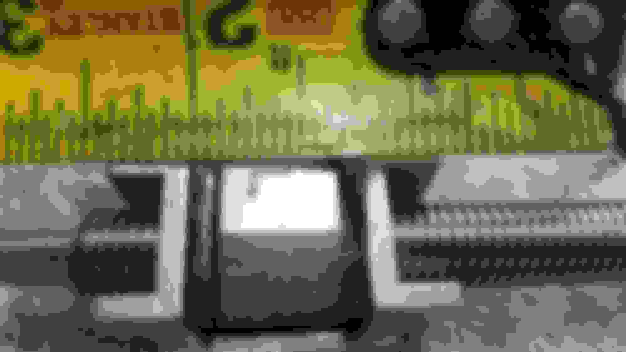
#11 - Mark both tracks with tape (blue in image) and cut so the can slide apart and note a precise measurement of a track are for future reference as well. Used for alignment when reassembled.
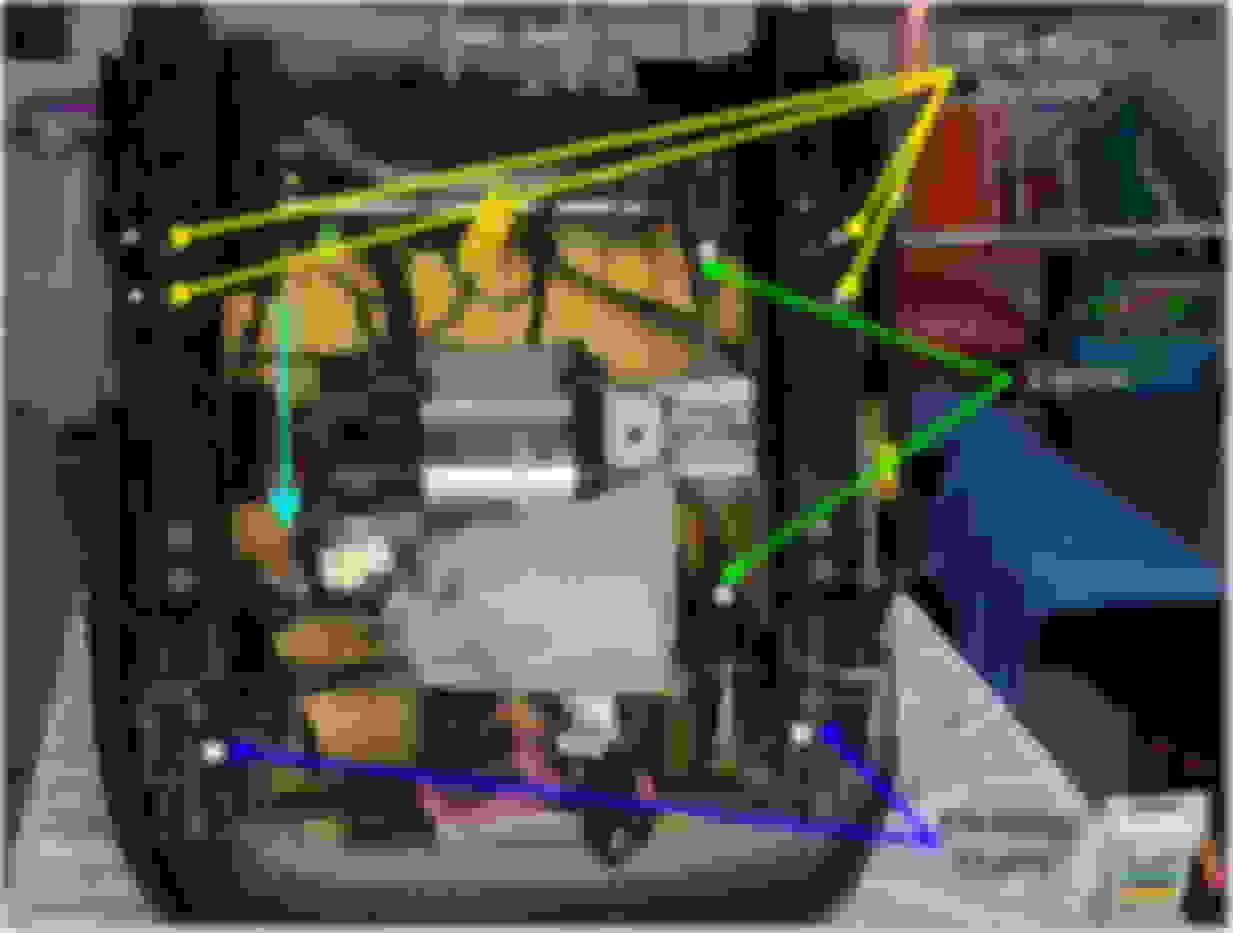
On the control panel side remove the 2 E12 Torx (Yellow) and I marked the openings (T)op & (B)ottom. This is a channel that will pass thru the similar u-shaped electrical/magnetic detector (Blue Arrow above)
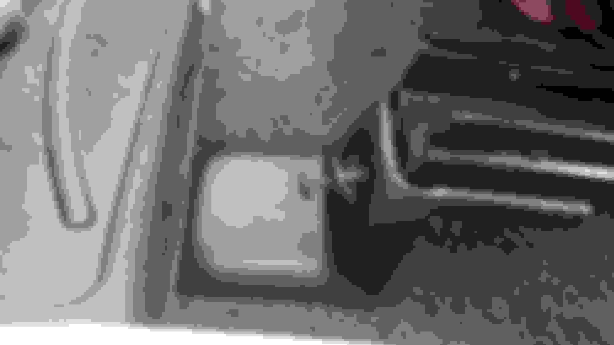
#12 - Remove 10mm (silver) screw on the top of the track by the seat belt screw stud that attaches the drive screw to the inner rail. Reference Silver Hex Cap Screw shown in image #5.
#13 - The entire mechanism will not slide out of the tracks
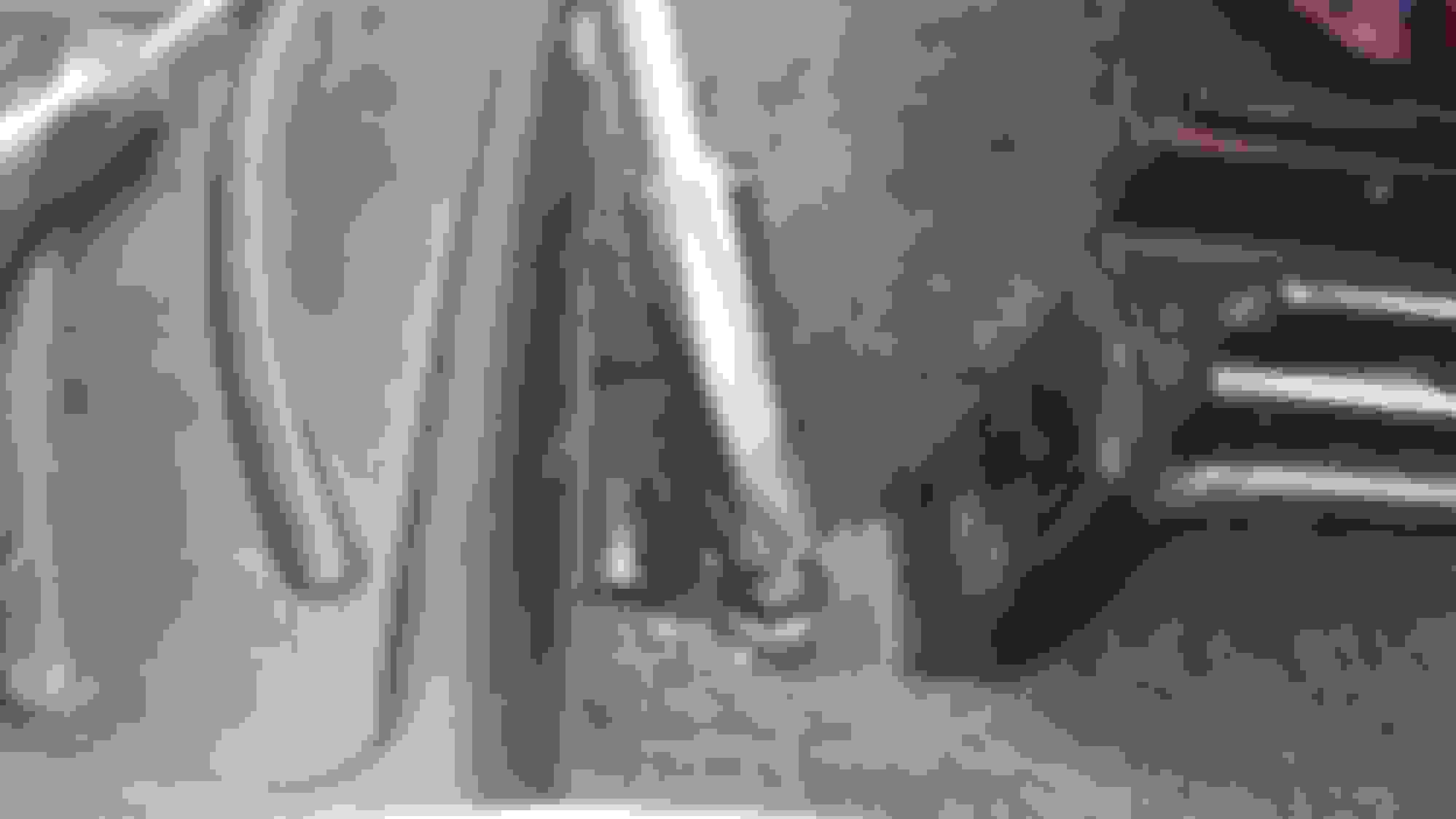
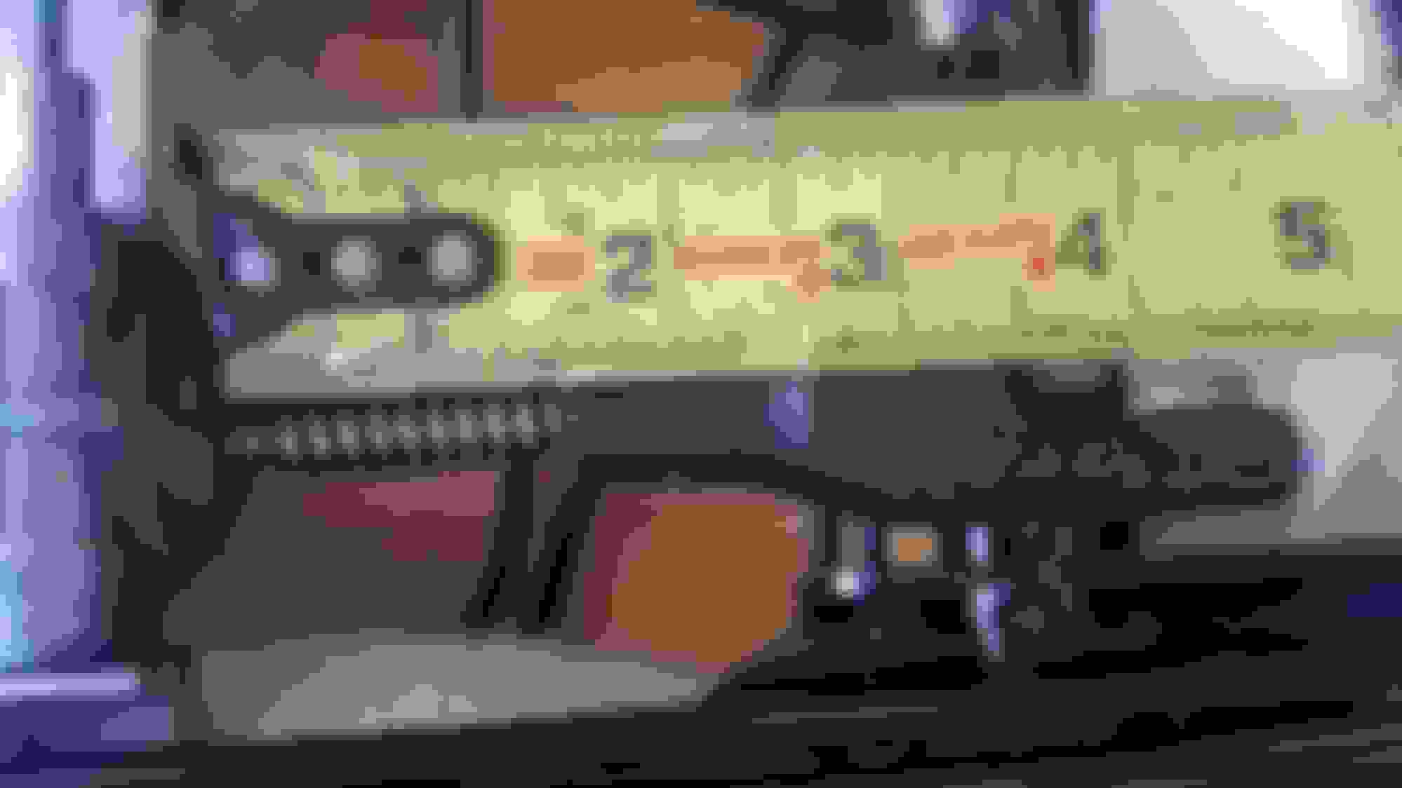
#14 - Note a precise measurement of the block location for reassembly [Yours will vary]. Unscrew the block assy from the screw drive
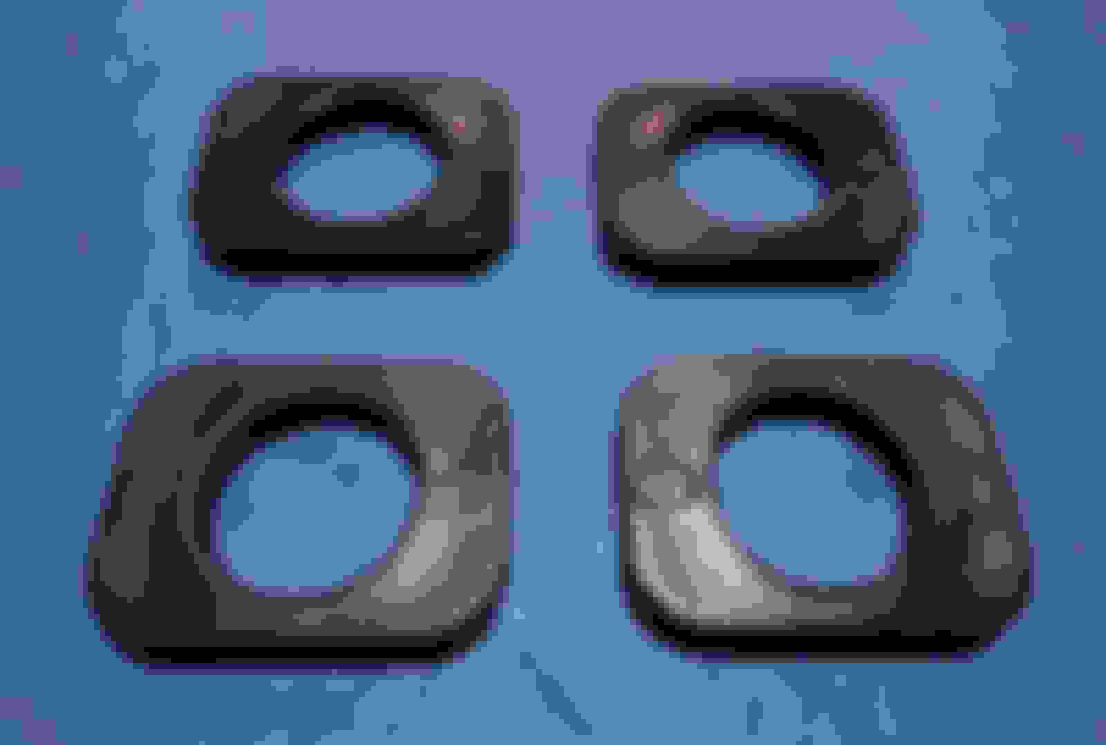
#15 - Block disassembled and cleaned. The rubber u-shaped bushing/grommet with holes in it inserts into the casting and then the block WITH V-SIDE UP (flat side down) inserts into the rubber bushing. Block Removed Block Disassembled. Again, note V-Side of Block Insert UP.
NOTE: My fix was to purchase 4 solid plastic inserts (2 per side) that replaced the rubber bushing insert. You can make them by griding thinner plastic washers and putting a flat edge on like a D-Ring, or purchase in sets from eBay, Amazon, and other 'vette part dealers. Search - C6 Corvette Seat Track Repair
#16 - Put the block assy back onto the screw drive to the measurement taken in #14 and (semi-generously.. you don't want so much it will drip off on the interior carpet when used) lubricate the long drive screw and insert it into the inner rail ensuring the flexible shaft ends are greased and FULLY SEATED into both ends. Note this flexible shaft is a square shape and must fully seat into both ends. If not properly seated the 10mm screw will not align with the track hole removed in #12.
#17 - Screw drive assy should line up with tap and screw holes marked T&B #12 ensuring the tape is aligned and the measurement is the same Blue Tape alignment verification Reconfirming earlier measurement
Reattach Plate marked T&B using EXTREME CAUTION AND DO NOT OVER TIGHTEN ANY OF THE E12 MALE TORX SCREWS. Very easy to strip these out.
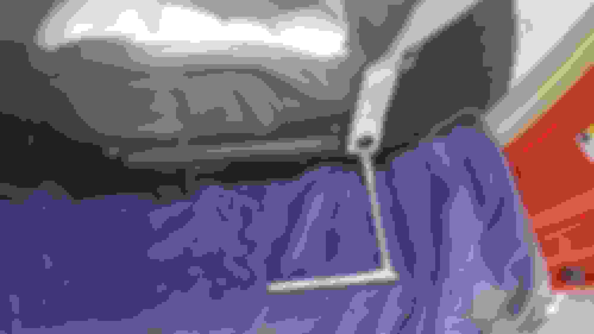
Also, ensure the plate channel lines up and will freely pass through the sensor channel. Screwdriver demonstrating alignment.
Right Side (Lap Belt buckle / Center Console side)
#1 - Exactly as on other side:
Note a precise rail measurement
Make with tape
Remove the 2 E12 Torx Head Screws
Remove the 10mm screw to release the Drive Screw Assy
#2 - Again, note a precise measurement of the Assembly for reassembly [Yours will vary].
#3 - Notice this inner block has an L stamped on it indicated Left Hand Thread
#4 - Reassemble as in #15-17 above, except w/o the Plate that had T&B marked on it that passed through the sensor.
Clevis (Rocking Seat on Acceleration repair). I removed them to inspect and lube threads as well.
#1 - Again, on each one note a precise measurement for reassembly
#2 - Remove the E12 Torx Shoulder Bolt from the Plastic Clevis, unscrew it and inspect for cracks, etc. and semi-generously lubricate the drive screw it was removed from.
NOTE: Web image of one with cracks EXAMPLE OF DEFECTS TO LOOK FOR
Image from this site showing if only cracked around threaded neck area repaired with a worm screw hose clamp ANOTHER THREADS HOSE CLAMP REPAIR
#3 - Screw the clevis back on to the drive screw to the earlier measurement and notice the E12 Torx screw only passed through the plastic clevis in one direction. One side allows it to pass through the plastic clevis, through the metal in the middle u-channel of the clevis and then screw into the other side of the plastic clevis for the connection.
Seat Re-installation:
*Reinstall the seat placing back on the 4 studs, connect the electrical connectors.
*Attach the lap belt 15mm nut and the the back 2 15mm nuts of the seat to the floor.
*Ensure there is nothing behind/under/etc. (tools, rags, etc) in the way of the seat retracting backwards.
*Attach the negative battery cable - In my case the seat automatically began full retracting to its preset programmed fully retracted exit location
*Attach the 2 front 15mm nuts and plastic covers.
Ensure any excess lubricant is wiped and does not get on carpet/interior.
DONE & Congratulations !! No sliding, rocking, or squeaking whichever you may have been going after if applicable here.

 09-01-2019, 11:26 AM