When you click on links to various merchants on this site and make a purchase, this can result in this site earning a commission. Affiliate programs and affiliations include, but are not limited to, the eBay Partner Network.
From: Henderson Nv-Rohnert Park/Sonoma C o. ca/born in NY Rockaway Beach.
Evap purge valve replacement.
Have the DIC p0449. Replaced the cap. Gonna replace the evap valve now.
What�s the best plan of attack to get it out.
im not the biggest of getting under a car alone. Do I go from the back of the car from the side ?
Only video I see only shows a fast shot of it and it�s position.
any help appreciated.
I just backed up on race ramps and did mine from the back.Kind of tight between the exhaust and frame but manageable.Hardest part was getting the spring clamp off the old one.Took longer to do that than anythind.Also a good idea to replace the clamp with a small worm clamp to make it easier if you have to do it again.Mine had to have an adapter harness also as the electrical connector was different.May want to make sure you have everything you need before starting this.DIY Fix for "Loose Gas Cap" indicator aka code P0449 w/Pics - CorvetteForum - Chevrolet Corvette Forum Discussion
This link may help.
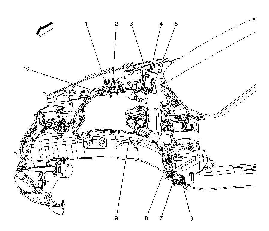
Before you replace the solenoid, pull the battery, and pull apart the connectors to clean the C180 and c184 connectors.
Locations 3 and 4,
Next pull the solenoid connector off, start the car, and check the pins on the connector with a multi meter to make sure you have 12 volts across the two pins.
The power and ground from the ECM to the solenoid connector runs through the C180 connector, then there is a wiring harness that runs to the back of the car down the torque tube off the C180 connector that has an S bend in it to clear the bell housing ,and the wires love to break at that S bend.
So it this harness that you see looped over the trans and running forward, but problem is up line at the bell housing.motor side isntead.
21/22/23 wiring harness that runs to the back of the car, through the torque tube tunnel area, and the wires live to break just after the bell housing, since it a hard point for the harrnes to be clipped to.
So no 12 volt power on the solenoid connector means either corrosion problem in the C180 connector, of wires broken at the S bend at the bell housing going back areas, that will need to be repaired isntead. To get to the S bend in the harness to repair the wires, muffler and torque tube cover needed to be removed.
If you do have power at the solenoid connector with the motor running, then bank that the solenoid is burnt out, and just needs to be replaced alone.
Have the DIC p0449. Replaced the cap. Gonna replace the evap valve now.
What�s the best plan of attack to get it out.
im not the biggest of getting under a car alone. Do I go from the back of the car from the side ?
Only video I see only shows a fast shot of it and it�s position.
any help appreciated.
Jack the rear high as you can; rest on pair of jackstands; remover right rear wheel; easy-peasey after that.
I don't think that my comment applies to you because you have lots of experience, but to someone new to these cars who is doing a search, make sure that you stop filling the tank when the nozzle shuts off the first time -- don't top off or overfill - and do sort of pull out on the gas cap as you tighten it. Crazy as it sounds, I got this code soon after purchasing my 2011 GS and treating it like other cars that I have owned. I tried these behaviors and haven't seen it sense.
Trick to filling the C6 with fuel, side ways the nozzle in the fill channel, with the hose on the nozzle aimed at the back of the car. When the nozzle clicks off, both tanks are full.
If you have the nozzle with hose downward towards the ground, nozzle is going to click off before the tanks are full, and your playing the multi click game trying to get the tanks full instead.
Hence C6 has two tanks, with a cross over tube between them, and with the hose of the nozzle pointing to the back of the car, allows the fuel to fill the tanks/pass through the cross over tube without pressure blocking the cross over tube from the stream of fuel out of the pump nozzle.
Before you replace the solenoid, pull the battery, and pull apart the connectors to clean the C180 and c184 connectors.
Locations 3 and 4,
Next pull the solenoid connector off, start the car, and check the pins on the connector with a multi meter to make sure you have 12 volts across the two pins.
The power and ground from the ECM to the solenoid connector runs through the C180 connector, then there is a wiring harness that runs to the back of the car down the torque tube off the C180 connector that has an S bend in it to clear the bell housing ,and the wires love to break at that S bend.
So it this harness that you see looped over the trans and running forward, but problem is up line at the bell housing.motor side isntead.
21/22/23 wiring harness that runs to the back of the car, through the torque tube tunnel area, and the wires live to break just after the bell housing, since it a hard point for the harrnes to be clipped to.
So no 12 volt power on the solenoid connector means either corrosion problem in the C180 connector, of wires broken at the S bend at the bell housing going back areas, that will need to be repaired isntead. To get to the S bend in the harness to repair the wires, muffler and torque tube cover needed to be removed.
If you do have power at the solenoid connector with the motor running, then bank that the solenoid is burnt out, and just needs to be replaced alone.
Sorry to revive an old thread. In the diagram you attaches, where are the c180a and c184 c0nnectors that you referenced? I have a 2013 Grand Sport that started giving me the "P0449 EVAP system vent valve control circuit/open" after I did a clutch job. It's also giving me a "U0122 Lost communication with Vehicle Dynamics Control Module" code and I wonder if I jacked up the wiring when I did the clutch job. Please help!
VCDM is the F55 module,and is located just above the ECM in the passenger side fender well (mounted to the sidewall cubby to the right of 5. Lost com on it (U code), may be the connector, or you forgot to reconnect its ground wire back to chassis.
3 and 4 are the connectors you looking for on the P0449 problem, so either behind the side of battery if wet sump motor, or behind the oil tank in dry sump.
As for P0449, disconnect the evap connector in back of car, put the car in run/motor off mode by pushing the bottom of start button for 5 seconds, and make sure you have 12 volts across the two connector pins for the evap. If you don't have 12 volts, then trace the wires back up the main connector above, disconnect the connector and check for voltage on the two wire pins on the ecm side of the connector. If voltage there, but not down line at back of car, then check the wires for continuity front to back each, and if you have a problem, going to be on the white 24 gauge wire, and at the S bend just before the thick plastic shield where the loom is connected to torque tube. if wire is cracked, don't bother splicing the connector, but pull a larger white shield wire, to replace the 24 gauge wire in the first place. Spice may hold for say a year, but with how thin the wire is, and it already cracked once, just a mater of time until it just cracks a few inches away from the splice again.
Chevrolet's "take a guess" parts number system along with many other design flaws
When you get a PO449. It's very confusing as to what you need to replace. When you ask a dealer parts dept. for the part number. They give you a number that you think is the emission purge valve solenoid. Most parts guys don't know what they are talking about. The number they give you, they say is for the emission purge valve solenoid. on the passenger side. But that's just a purge valve on that side. No solenoid. The purge valve solenoid and cannister combination is on the driver's side. I bought the part suggested by Chevrolet parts dept. called emission purge valve solenoid. No solenoid in this part. Just the purge valve. Very misleading, like everything made by GM. The actual selonoid combined with the cannister is on the driver's side. Parts guy won't even mention that part to you. And when you buy that combination part, it's a new version. Different electrical hookup. You need to buy a new type harness to be able to connect to system. They don't mention that. What a cluster. Like the other C6 screw ups. Want to drop your oil pan and change the gasket, you have to disassemble part of your front suspension. Want to change the transmission filter, you have to loosen the transmission and jack it up so you can get to the rear transmission bolts that are hidden by a cross member. Cars that you pay extra for navigation, doesn't give you a mp3 aux jack so you can play music from your phone. Cars without navigation have the jack installed. Does all this make sense to anyone. Automatics get stuck in park time after time. The seat foam has no layer of protection to keep the cushion wires from easily cutting through it which you need to replace. Can anyone defend any of these GM engineers design screw ups? A joke.
This �new type harness� you speak of is for the EVAP VENT VALVE and not the purge valve�there is nothing on the driver side engine compartment related to the purge valve if that is what you are taking about�the vent valve is on the passenger side rear frame rail�I could not see them selling you just the solenoid part of the purge valve�post a picture of what they sold you�this is the purge valve located on my 08 as well as yours�.you have to give them the correct information to get the right part.
The purge valve on the passenger side part # 12735397. The description of the part makes you think it has the solenoid included with it. Does not. The purge valve solenoid and small canister is on the driver's side. Not in engine bay. I think location is possibly a little forward of the location of the purge valve location on the passenger side, but on opposite side. After searching you tube, I never saw a reference to this solenoid and cannister on driver's side. When you ask parts people about replacing the evap purge valve solenoid, they don't even mention the part on driver's side. No videos on YouTube for purge valve emission solenoid replacement mention this part. They only show replacement of the purge valve next to gas tank on passenger side. Had replaced. Purge valve on passenger side was fine. It was the solenoid on the driver's side that was bad. The new part needed a redesigned harness to make connection. My code was PO449. Not specific on what part is defective. I finally found one description of the driver's side replacement part after a Google search. If you get a PO449 code, you will see what I i mean. I gave parts dept a proper description of the code and what it said the issue was. Not much else I could describe to them. But passenger side purge valve is the only part mentioned as a replacement. Cluster.
My Friend, you are VERY confused on the EVAP system nomenclature and locations...the EVAP purge valve and the electrical solenoid which it is attached to are BOTH in the engine bay PASSENGER side on the top picture...the solenoid is NOT separate and in a different location ...I have NEVER seen the solenoid sold separately as you can see by that part number....PLEASE enclose a picture of that solenoid as a separate part you received...the VENT VALVE and EVAP Cannister are in the rear of the car on the passenger side...the Vent Valve is the last picture and is taken looking up....the Cannister is behind an access panel in the right rear wheelhouse area...it is the 2nd picture and you can't see the entire cannister...if you don't believe me that's fine but whatever EVAP issue you have I hope you get it resolved !!!....if you have a 2008 like myself limit you YouTube video searches and locations of those parts just to the 2008 model year.
The evaporative emission (EVAP) control system limits fuel vapors from escaping into the atmosphere. Fuel tank vapors are allowed to move from the fuel tank, due to pressure in the tank, through the vapor pipe, into the EVAP canister. Carbon in the canister absorbs and stores the fuel vapors. Excess pressure is vented through the vent line and EVAP vent solenoid valve to the atmosphere. The EVAP canister stores the fuel vapors until the engine is able to use them. At an appropriate time, the control module will command the EVAP purge solenoid valve ON, allowing engine vacuum to be applied to the EVAP canister. With the EVAP vent solenoid valve OFF, fresh air is drawn through the vent solenoid valve and the vent line to the EVAP canister. Fresh air is drawn through the canister, pulling fuel vapors from the carbon. The air/fuel vapor mixture continues through the EVAP purge pipe and EVAP purge solenoid valve into the intake manifold to be consumed during normal combustion. The control module uses several tests to determine if the EVAP system is leaking.
Large Leak Test
This tests for large leaks and restrictions to the purge path in the evaporative emission (EVAP) system. When the enabling criteria has been met, the control module commands the EVAP vent solenoid valve ON and the EVAP purge solenoid valve ON, allowing vacuum into the EVAP system. The control module monitors the fuel tank pressure (FTP) sensor voltage to verify that the system is able to reach a predetermined level of vacuum within a set amount of time.
Small Leak Test
The engine off natural vacuum (EONV) diagnostic is the small-leak detection diagnostic for the evaporative emission (EVAP) system. While previous leak detection methods were performed with the engine running, the EONV diagnostic monitors the EVAP system pressure or vacuum with the ignition OFF. Because of this, it may be normal for the control module to remain active for up to 40 minutes after the ignition is turned OFF. This is important to remember when performing a parasitic draw test on vehicles equipped with EONV.
The EONV utilizes the temperature changes in the fuel tank immediately following a drive cycle to use the naturally occurring vacuum or pressure in the fuel tank. When the vehicle is driven, the temperature rises in the tank. After the vehicle is parked, the temperature in the tank continues to rise for a period of time, then starts to drop. The EONV diagnostic relies on this temperature change and the corresponding pressure change in a sealed system, to determine if an EVAP system leak is present.
The EONV diagnostic is designed to detect leaks as small as 0.51 mm (0.020 in). The diagnostic can determine if a small leak is present based on vacuum or pressure readings in the EVAP system. When the system is sealed, a finite amount of pressure or vacuum will be observed. When a 0.51 mm (0.020 in) leak is present, often little or no pressure or vacuum is observed. If the test reports a failing value, DTC P0442 will set.
Canister Vent Restriction Test
If the evaporative emission (EVAP) vent system is restricted, fuel vapors will not be properly purged from the EVAP canister. The control module tests this by commanding the EVAP purge solenoid valve ON, commanding the EVAP vent solenoid valve OFF, and monitoring the fuel tank pressure (FTP) sensor for an increase in vacuum. If the vacuum increases more than a calibrated value, DTC P0446 will set.
Purge Solenoid Valve Leak Test
If the evaporative emission (EVAP) purge solenoid valve does not seal properly fuel vapors could enter the engine at an undesired time, causing driveability concerns. The control module tests for this by commanding the EVAP purge solenoid valve OFF and the vent solenoid valve ON, sealing the system, and monitors the fuel tank pressure (FTP) for an increase in vacuum. If the control module detects that the EVAP system vacuum increases above a calibrated value, DTC P0496 will set.
Check Gas Cap Message
The control module sends a class 2 message to the driver information center (DIC) illuminating the Check Gas Cap message when a malfunction in the evaporative emission (EVAP) system and a large leak test fails.
EVAP System Components
The evaporative emission (EVAP) system consists of the following components:
EVAP Canister
The canister is filled with carbon pellets used to absorb and store fuel vapors. Fuel vapor is stored in the canister until the control module determines that the vapor can be consumed in the normal combustion process.
EVAP Purge Solenoid Valve
The EVAP purge solenoid valve controls the flow of vapors from the EVAP system to the intake manifold. The purge solenoid valve opens when commanded ON by the control module. This normally closed valve is pulse width modulated (PWM) by the control module to precisely control the flow of fuel vapor to the engine. The valve will also be opened during some portions of the EVAP testing, allowing engine vacuum to enter the EVAP system.
EVAP Vent Solenoid Valve
The EVAP vent solenoid valve controls fresh airflow into the EVAP canister. The valve is normally open. The control module commands the valve ON, closing the valve during some EVAP tests, allowing the system to be tested for leaks.
The fuel tank pressure (FTP) sensor measures the difference between the pressure or vacuum in the fuel tank and outside air pressure. The control module provides a 5-volt reference and a ground to the FTP sensor. The FTP sensor provides a signal voltage back to the control module that can vary between 0.1�4.9 volts. A high FTP sensor voltage indicates a low fuel tank pressure or vacuum. A low FTP sensor voltage indicates a high fuel tank pressure.