When you click on links to various merchants on this site and make a purchase, this can result in this site earning a commission. Affiliate programs and affiliations include, but are not limited to, the eBay Partner Network.
trying to diag my speedo not working, got under the car and saw this connector unplugged. any idea what it is? 2007 z51 that has been swapped to a base model t56. so idk if there is something extra on the z51 t56 or not. this photo is taken from the passenger side where the diff and trans meet.
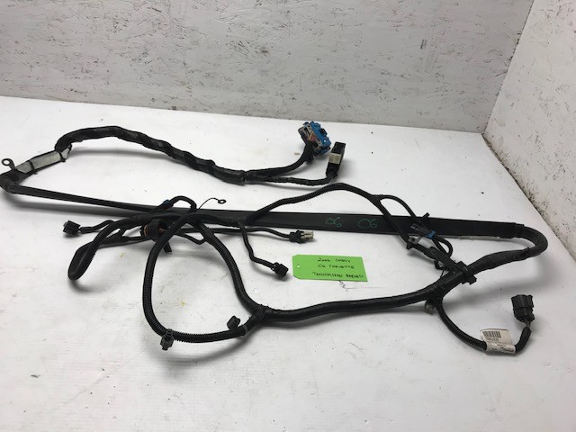
I unplugged and reconnected the VSS, and verified in hptuners that the vehicle speed is reading 0. Here is a photo of it next to the VSS connector. Im assuming this is just a temp sensor for z51 option? The second photo appears to be from a c6z and I dont see that wire present? Anyways I pulled the speed sensor because a new one is coming tomorrow. I sure hope that is the issue because I have a tune scheduled for Saturday and I am in scramble mode to get this figured out. I did already check the C180 and C184 connectors. They look very clean.
find the wiring colors on the VSS connector, then on the C connectors at the battery with them disconnected, jump the VSS connectors pins together with jumper, then check at the C connector to make sure that the wires are not broken in the harness in the torque tube area.
Or just swap the VSS sensor and pray like hell that the wires are not broken in the harness, and this causing the problem.
The C184 pinout I found online says VSS is yellow/purple.
When I got under the car the wire at the VSS is orange w/ black stripe and tan w/ white stripe. Guessing the diagram is wrong year/option, but its the only one I can find.
EDIT*
Those wires that are connected to my VSS connector according to the diagram are from trans fluid temp sensor. The speedo stopped working after I had someone change my clutch so I wonder if they re-connected the wrong connector somewhere.
Well I think yall just watched me figure it out. They mixed up the wiring. Found the yellow/purple wire on another connector but its slightly damaged because they put it in the wrong slot. Luckily I preemptively bought that but will try to repair it first.
Depending on the module, and even if F55or not, the pinning of the wires at the connectors are all different.
So short of pulling up GMSI and having your year and model with or without F55 to give you the correct wiring diagrams, easy way is to just look at the VSS connector wires colors, trace them back to the C connectors up front, and check to make sure that wires are not broken.
Also, be dam sure to check the connector wire colors both sides for match ups, since again, different pining of different model loom connectors and could be wires are fine, but rear wire loom changed and its not pinned the same as the car side of the connector.
Also, on the rear wiring loom, its loose with single protector wrap all the way to the start section of the Torque tube, and at that section going down the TT, extra plastic protector on the loom . So between motor heat, and Upper S part of the loom moving, but added plastic outer piece section not moving, it at this point that the wires love to crack.
The fact that all this started around the time of the clutch swap when the drive line was R&R, either swapped loom, or wires cracked when the loom was moved around with the Drive line Removal and reinstall.
As for if you do have cracked/split wires, cross pipe and tt cover plate have to be remove, and if you do need to repair the wires just in front of the added plastic wrap, do not solder splice the wires back in there. Pull back a section of the plastic hard shielding to put one section of the wire splice under it, then work your way back up the S bend to spice the other end up back up there. Hence brand new unmolested wire as the end of S bend to hard plastic outer shielding piece.
The person who did the swap tried to plug in the trans temp sensor wire into the VSS. Then smashed the VSS wire into a connector that it wasnt supposed to go to. IDK why that never threw any codes but after musical connectors I matched everything up properly and it works now. The connector that I mentioned at the beginning of this thread was what the VSS was plugged into. It goes on the drivers side of the trans. What is that?