When you click on links to various merchants on this site and make a purchase, this can result in this site earning a commission. Affiliate programs and affiliations include, but are not limited to, the eBay Partner Network.
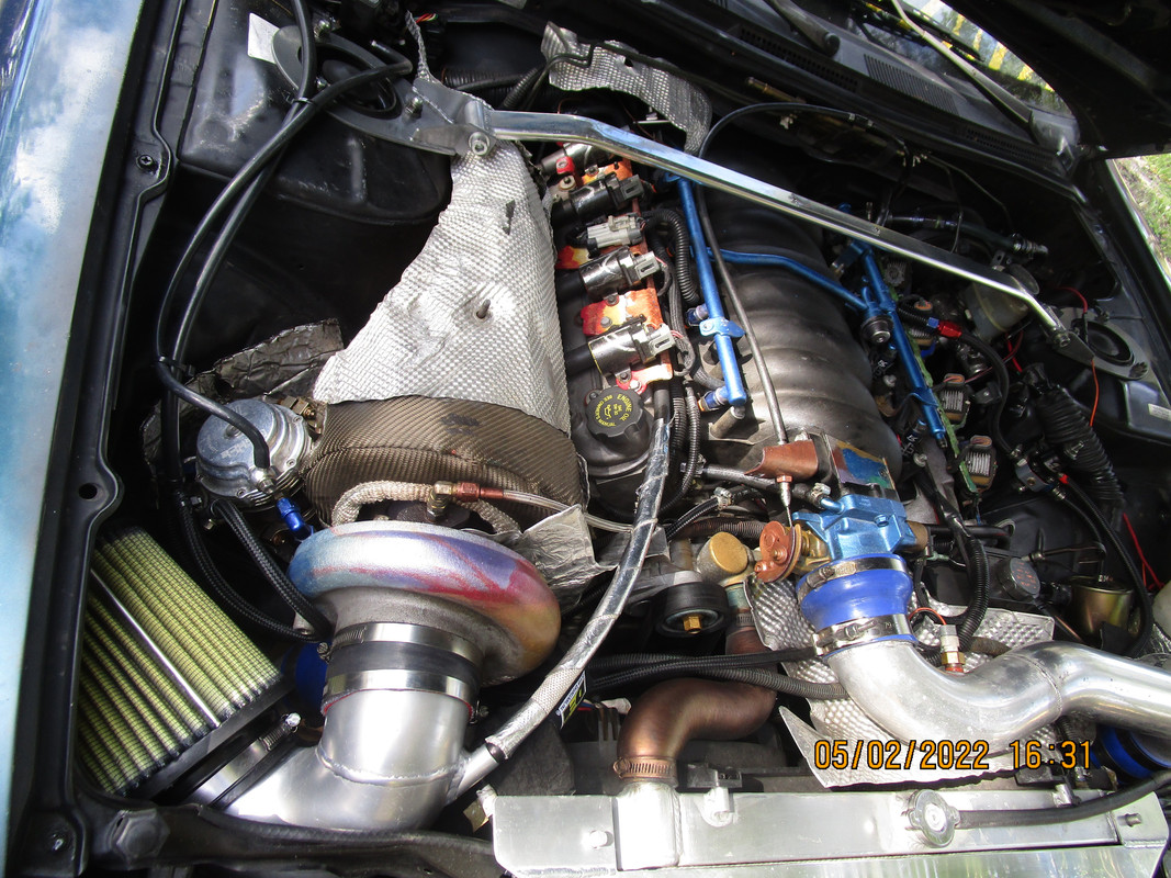
Many times, theories and "on paper" designs don't always work out in practice. Or work as well as originally thought. I have no interest in arguing with anyone here. But, I'd like a laymans, or technical explanation, as to why my built LS7 wet sump engine has now traveled over 52,000 miles, including over 2,000 in the last 6 weeks, and uses absolutely no oil......Well, MAYBE 4 or 5 ounces. Engine has almost 5,000 miles on this oil change (mobil 1 0w-40), and I've added 1/2qt. of oil. Engine has absolutely ZERO PCV setup. It has interconnected breather tubes venting to an opaque plastic bottle, which I drain once in awhile. Maybe every 2-3 months. A PROPERLY designed, and executed PCV system probably has advantages. With the OEM PCV system, I saw my intake filling with oil, some of which is STILL in there. IMHO, NO advantage with the very poor OEM design. My main point; venting to atmosphere was effective for the first 70 years of the ICE. I have proof under my hood that venting to atmosphere is not a death sentence for an engine. Please feel free to comment. I just don't want to argue about it.......
Stollen from internet:
Crankcase ventilation systems can be classified as either ingestive or non-ingestive. An ingestive system vents the blow-by into the engine where it returns to the combustion process. A non-ingestive system vents blow-by to the atmosphere.
OP's question was related to "ingestive" crankcase ventilation, which BTW is superior to just venting into atmosphere via breathers. Now, one can also use exhaust pulses to help with creating some vacuum in the crankcase. That would be third best option? First best option being installing a vacuum pump. It all works, just not equally well, performance wise, emissions wise and longevity wise.
Where do you vent the crankcase? Into the engine compartment?
Into a vented bottle near the bottom rear edge of the radiator......
OP did change his air filter to more open style which potentially reduced PCV system ability to evacuate gasses out of the crank case by lowering the vacuum signal in the tube out of the valve cover. Here is where his catch can is helping to collect the oil out of the valley cover, that is potentially due to altering PCV system by installing open element air filter.
The only way to know if this is the case would be to measure crankcase pressure with OEM air intake box/filter and with aftermarket air intake box/filter and see if there is any difference one from another. So the catch can in this case is only helping to PARTIALLY correct the issue of altering PCV system by collecting oil that shouldn't be there in the first place if the system was not altered. Ok, I would agree with this, however there is more to it. The engine will have some blow by when it's cold (not warmed up) or when it's revving high even if PCV system was not altered. From this perspective, catch can is still helping. This is why most people see oil in their catch cans during winter time, with lots of cold starts and cold running engine and if the engine is revved high and pushed hard, like in racing situations. Bottom line, catch can is not hurting, and it does help in certain situations. So far so good for the OP on catch can installation but not so good on open air filter element installation.
Now, with performance enhancement in mind, less restrictive air filters are better. Everyone knows this and wants this, we should be able to agree here. What do you think is the correct way to address PCV system issues caused by installation of less restrictive air filter? Vacuum pump is the only option? Or are there other options?
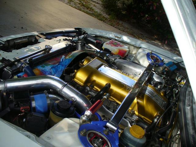
Turbocharger is the answer. Turbo offers the advantage of high vacuum inlet, high crankcase scavenging and as much power as you want. All my cars are turbo since 2002.
[/QUOTE] NEVER put a breather on any gasoline combustion engine crankcase. It must have pressure below atmospheric at all times. It must have a PCV system. A breather breaks the PCV system. The definition of PCV literally translates to 'positive crankcase ventilation' which implies pulling out combustion gas using a vacuum. A breather is not a vacuum, that is positive pressure and will contaminate the engine oil supply and lead to ruined piston rings.[/QUOTE]
It appears to me that this answer does not address the question of a breather with a check valve in it. If such a breather has a check valve that only opens and lets out crankcase pressure that is above atmospheric, and closes the moment atmospheric pressure and crankcase pressure equalizes (which is the case with this type of breathers as the check valve ball uses pressure difference, and also gravity, to open and close), wouldn't the breather in this case be aiding PCV system to help evacuate excessive crankcase pressure more effectively? Since it is not letting any air in into the crankcase, it is only letting the gasses out of the crankcase. Not as effective as a vacuum pump but helps?
In addition, the breather with check valve is typically installed on the same side valve cover that has evacuation tube in it, so it shouldn't affect direction of crankcase gasses flow, correct?
I'm sorry you don't seem to understand what a pressure scalar is because my response DOES address the question of breathers. Pressure has no direction like temperature it can only be measured in 1 infinitesimal location at a time. If you are measuring a positive pressure anywhere in the crankcase then this is not PCV. A positive pressure is needed to push oil vapors out of the engine like into the front main or rear main or valve cover seals, this is how oil seals begin leaking, and this is what will also blow out of the crankcase if you put a vent on the engine. Its like you connected an air compressor to the engine crankcase, not good. There is not a single engine ever produced from any manufacturer in the world since PCV has been invented which has a positive pressure in the crankcase at wide open throttle on a factory engine with factory paper filter. If it does then it is no longer OEM and original engine and will have a shorter lifespan. Modern engines have crankcase pressure sensors because it directly correlates to engine health. It is considered a performance engine necessity for the top engine tuners in the world for high output vehicles.
This information is available but it does not make anybody money. The people make money from catch can sales, not from keeping the engine factory original. So the attempt to sell cigarettes like catch cans over-rides the good information obscured.
Examples https://www.theturboforums.com/info/...rs-101.378656/
"you would never want to use a can with a breather on it, as that is breaking the evacuation cycle leaving the contaminants in the crankcase, and also allows pressure to build and be pushed out which is never proper. That technology went out with the 1980's."
"Further, as the piston rings rely on pressure above, and suction below to maintain proper stability, if a constant evacuation system is not used piston rings experience "Ring Flutter" that compounds the blow-by issue and results in even more problems over time."
----------------------------------------------------------------------- https://www.yellowbullet.com/threads.../post-27770338
"You don't just want to "vent" the case. You want vacuum on it, esp. in boost. Exhaust evac. kit is the cheapest and easiest way to get a decent vac pull on the crank case IMO.
I went a step further and used an electric pump as described above. My pump kicks on at 1lb of boost"
----------------------------------------------------------------------- https://www.yellowbullet.com/threads.../post-10377000
"You will also have oil leaks too with positive crankcase pressure."
-----------------------------------------------------------------------
"If you are building crankcase pressure (from blowby on the power stroke without proper evacuation), this pressure can also go the other way past the rings during the intake stroke. You can get oil ingestion to the cylinder past the rings without ever going trough the traditional PCV route (intake system)."
-Greg Banish
-Calibrated Success, Inc.
What I recommend is look at how OEM engines are configured, particularly Turbo factory engines, because turbocharged will produce far more blow-by per displacement than any natural aspirated engine should. It is harder to control turbo engines so if they can do it, you certainly should be able to. Look at 1995-2002 Toyota Supra and Nissan Skyline engines as a great example, they achieve 250,000 miles with Original equipment and come apart looking brand new after 20 years. On this site look for posts by LDB which exemplify the cleanliness action of PCV. Here is one of his quote
"The reality check problem I’ve always had with catch cans is that as far as I know, not a single car maker in the whole world uses them, not even the ultra high performance and price guys like Ferrari. They aren’t even used on diesels, all of which are direct injection, which kind of knocks out the C7 DI worry. So do I go with the unanimous vote of all the powertrain design engineers of all the world’s car makers, or the postings of some internet engineers and catch can salesmen. Hmmmm. Doesn’t seem like a tough choice." -LDB https://www.corvetteforum.com/forums...post1587279447
Another observation; PCV system will pull fresh air into the crankcase at idle due to crankcase pressure being lower compared to air intake tube pressure where valve cover evacuation tube is connected. Isn't this a crankcase breather of sort?
You have to look at the direction of flow to understand the conditions and the rate of change of pressure inside a crankcase. At idle and cruise the direction is towards the intake manifold PCV valve or restrictive orifice. At Wide Open Throttle the flow direction is reversed in the fresh air inlet which becomes the outlet instead. The difference is during idle and cruise the blow-by is extremely reduced so there is very little mass entering the crankcase which makes it very easy to evacuate the blow-by and maintain fresh air and low pressure. At wide open throttle the blow-by is increased and it is much more difficult to remove all of the blow-by so pressure might begin to build if there is insufficient evacuation in the form of a pressure gradient, which starts low behind the air filter and pulls on the crankcase from the factory. This is why all OEM engines use air filters which are slightly smaller than they seem to need- pick any engine from a corvette to toyota to subaru to nissan to honda- they all pick up power when a high flow filter is installed, some percentage like 2% or whatever it is. The power they gain comes from ruining the PCV system and allowing contaminants to stay inside the engine and letting the crankcase pressure rise and force oil into engine oil seals leading to oil leaks and stuck ruined piston rings and ruined cylinder walls. You are sacrificing the engine lifespan for a couple percent of power when you 'upgrade' the factory air filter of any engine.
The OEM engineers have already figured the PCV system. They (we can) calculated the mass of oil ejected, you have to when designing an engine and for it's baffle system considerations. Modern vehicles have crankcase pressure sensors to protect engine seals piston rings are engine seals and accumulate oil (which form hard carbon deposits over time and seize the ring destroying the cylinder wall) This is an extremely important topic.
When crankcase pressure rises combustion gas carries oil from the crankcase and moves up through the piston ring into the combustion chamber (ref: https://www.corvetteforum.com/forums...post1606142803)
The crankcase must be set to a negative pressure or it will blow oil droplets out from every seal and into every baffle.
If you do not measure the pressure its the same as installing a fuel regulator without checking or setting the fuel pressure.
-as the hoses becomes longer (friction) crankcase pressure rises and with it blow-by and oil liquid droplet size/density increase
-as hoses become larger (volume) crankcase pressure will be higher given some input energy availability
-as hoses become larger (volume) the rate of change of crankcase pressure is smaller given some input energy duration for wide open throttle
-cooling combustion gas reduces its average velocity and increases the energy requirement to move blow-by gas because less is supplied by the gas in form the heating
-as hoses become larger & longer (volume/friction) oil droplet radius and density increases in the blow-by gas
-the higher the pressure at the post air filter location the higher the crankcase pressure overall for wet and dry sump engines that do not have vacuum pumps at wide open throttle.
I have taken the time to show how one may mathematically approach this subject in terms of friction, gas density, oil droplet radius/density, and mass flow which can help visualize these outcomes using analytical solutions to compare scenarios.
1. Start with an equation predicting mass per unit time (mass/time) of combustion blow-by fluids produced at wide open throttle as a function of piston-wall clearance and crankcase pressure.
1A. Convert mass/time to volume/time using various temperatures for crankcase gas (a second equation that gives volume of crankcase gas based on temperature).
With #1 we have mass/time and volume/time blow-by gas equations
2. With a range of crankcase volumes (include all PCV lines and volumes) dedicated to containing gas as a mixture of combustion products and atmosphere, Determine the energy needed to move a mixture of blow-by combustion fluids contained within the crankcase and piston rings through a 1/4" and 3/8" and 5/8" Hoses/Volume from the crankcase (assume any static constant % of blow-by gas for all comparisons) being evacuated to any PCV pressure supplied by the air filter (or atmospheric pressure (vented) to assume no air filter or a perfect air filter) at varying lengths and frictions of hose and varying total volume.
With #2 we have energy necessary to organize and move blow-by mass/volume of gas through various hoses at various lengths (friction/volume) and temperature.
2B. Find available input energy (Head or velocity improver term) based on PCV supplied pressure above, same, and below atmospheric (Vacuum pump and/or Wet sump pressures: 10"Hg, 6"Hg, 2"Hg, Atmospheric pressure 0PSI, and positive crankcase pressure (1psi, 2psi, 3psi) Note: positive pressure adds energy and raises gas density but also increases blow-by, oil droplet radius, and oil droplet density.
3. Create an equation which will find resulting crankcase pressures with varying crankcase volumes, pipe wall friction(pcv hose length, gas volume and temperature) & blow-by gas mass/time based on energy supplied(pay attention to velocity in the tubes) using PCV applied absolute pressure at wide open throttle given different air filter pressure drop scenarios and pipe surface friction coefficient, do not use an ideal gas equation. Account for the sizes of molecules and use Reynolds for the varying pipe wall friction if possible. Make sure as #1 states to include blow-by as a function of crankcase pressure (more pressure in the crankcase = more blow-by = more mass to evacuate). Be sure to include temperature and it's impact on gas density and volume as it flows through a tube while cooling down at increasing large distances and volumes. You do not have to calculate temperature gradients it is okay to average temperature for the entire crankcase volume because temperature to volume is linear enough. Use temperature to find average velocity (change in x / change in time) of gas to get flow rate at some density. mass flow is equal to density*velocity*area
In #3 we take energy available and compare it to total volume/mass of blow-by gas and use these (energy vs mass and temperature) to determine resulting crankcase pressure based on crankcase volume (flow rate mass/temperature sets the pressure over time at different volume). Hint: equate input mass to output mass at some control volume V for compressible gas (neglecting Z axis or height from all equations).
4. Setup an equation which inputs crankcase pressure from #3 to find the magnitude of radius and density at varying crankcase pressures for oil droplets produced within crankcase using the equations from 'the oil drop experiment performed by Robert A. Millikan and Harvey Fletcher in 1909'. Find the volume of liquid oil droplets in a given volume (based on temperature and pressure, you may use ideal gas equation for oil as it travels with gas in a tube) and make sure to add that for a total volume of combustion gas with suspended oil droplet volume.
#4 we add oil droplet volume to crankcase gas and find new total volume (It can be a coefficient or analytic solution or series) which includes some density/radius of oil droplets.
5. Using oil droplet density & radius at varying crankcase pressures, find transported mass of oil at various resulting crankcase pressure and volume/time rates of evacuation (based on mass, temperature and pressure find volume gradient along the PCV system). It must be volume and not mass, the mass/volume of oil is moved with a transported volume of combustion gas at some oil droplet density, not its mass. Make sure to include temperature drop along some length/volume of tube as part of the gas density equation in longer sections of tube or volumes with a temperature drop.
#5 lets us know how much oil will be ejected with the blow-by gas and how much additional blow-by gas we would need to evacuate
Note
you may neglect reasonably large enough catch can volumes and other large volumes in series or parallel with WOT PCV from friction energy dependence but not volume of gas to energy dependence.
Have you ever considered making a tool for measuring this for a few different vehicles?
For racing community this is all common sense and been done 9999 times. On forums like this not oriented around the importance in racing & data collection are not used to this level of thinking.
I didn't make any of this up. I am only trying to bring it down from OEM level and Racing environments to general automotive forums like this. They make the catch can mistake on the racing forums, too. But as you can see many users are wise to the situation and using the crankcase systems with monitoring to keep oil inside the engine. Including myself I made a video of how to do it yourself the cheapest way possible and built a demonstration turbo vehicle for daily driving.
Of course! Just no vacuum, no PCV. If venting to atmosphere, if you don't direct the oil mist to some sort of container, it will end up all over the pavement and car. This would be nobody's idea of a good time. BTW, I'm still waiting for King Talon, or anyone else, to explain why my engine uses only 4-5 ounces of oil every 5,000 miles after accumulating over 52,000 miles, and has no oil leaks anywhere, with no PCV, no vacuum.....
Of course! Just no vacuum, no PCV. If venting to atmosphere, if you don't direct the oil mist to some sort of container, it will end up all over the pavement and car. This would be nobody's idea of a good time. BTW, I'm still waiting for King Talon, or anyone else, to explain why my engine uses only 4-5 ounces of oil every 5,000 miles after accumulating over 52,000 miles, and has no oil leaks anywhere, with no PCV, no vacuum.....
King Talon is odd duck. But don�t get me wrong, he does have many good points. Installing turbocharging system to correct an issue in normally aspirated engine PCV system may not be one of them. That just goes to tell you that even he doesn�t understand everything lol
King Talon is odd duck. But don�t get me wrong, he does have many good points. Installing turbocharging system to correct an issue in normally aspirated engine PCV system may not be one of them. That just goes to tell you that even he doesn�t understand everything lol
I find it hypocritical of you while using an obvious troll account to sling mud at him. Come use your normal account or was it banned?
For racing community this is all common sense and been done 9999 times. On forums like this not oriented around the importance in racing & data collection are not used to this level of thinking.
I didn't make any of this up. I am only trying to bring it down from OEM level and Racing environments to general automotive forums like this. They make the catch can mistake on the racing forums, too. But as you can see many users are wise to the situation and using the crankcase systems with monitoring to keep oil inside the engine. Including myself I made a video of how to do it yourself the cheapest way possible and built a demonstration turbo vehicle for daily driving.
Specifically to test crankcase pressure on the C6 LS2 could the driver rear valve cover port that is blocked be used for a two bar setup? Or should I think more like tapping a port in the valley plate? I will buy or build something. Fun project and learning!
Good idea. It is a fun project and not hard to do.
Here's a look at the setup I used, to give you some ideas. It's made up of off the shelf parts and pretty easy and inexpensive to put together. You could do the same or do something different.
First I got an AC Delco pressure sensor, part no. 19418807 the same one used as a MAP sensor on my car.
It was plumbed into the valve cover PCV line with a T fitting
Then I made up a little harness to provide 5v to the sensor and connect it's output to my MPVI 2+. Same as you would do adding a wideband sensor.
Now I can see crankcase pressure in real time, and record the data to look at when I'm not driving.
Here's an example of a log. Crankcase pressure is the red line on the bottom graph. Note how little it changes as MAP, MAF, RPM and throttle position change dramatically as I accelerate in 3rd and shift to 4th.
Bottom line is that crankcase pressure stays right where it should be, about 5kpa less than ambient barometric pressure. So the PCV system is doing it's job just fine.
BTW, this was with the MM 5+ catch can installed. YMMV
Thanks I can do that install and get that part easy. I am not sure 12v to 5v though. I do have a lap top with hp tuners for my car. I would think if I got a electric pressure gauge it would do the 12v to 5v. But if I wanted to display it in hp tuners I would have to figure out the 5v myself. How does your harness handle that?
The pressure sensor I used is connected to the car's 5v reference buss in it's stock application. You will notice in the picture it has 3 terminals labeled 5v (5v ref), Vout (sensor output), and GND (ground). To get the 5v I tapped into the wiring for the A/C pressure sensor, which is conveniently located close to the front of the passenger side valve cover. I made a little pigtail that connects between the A/C sensor connector and the connector in car's wiring. That's the two black connectors in the harness picture. The gray connector plugs into the MAP sensor. The long cable goes inside the car to connect to the MPVI 2+ using HPTuner's ProLink cable.
Watch my video I show exactly how to do it yourself. You can copy me exactly I used a 1-bar map from any vehicle and a multi meter on the crankcase very simple a baby can do it. also make sure to pressure test like my pressure test video- a different video that I show how to pressure test the plumbing properly and identify the pcv leakage and style. Its a demonstration car I make it clear how to build and tune the vehicle properly. My build thread contains everything from selecting a turbo to tuning it I provide a file and logs and what I do to the transmission etc... whole car thing done.
One of those critical steps is modifying the engine to make more power is turbo. Turbo lets you avoid making engine mods directly, you can keep a mostly factory engine and make limitless power to the capacity. Turbo engines have the least stress of any combustion engine. With a turbo I can select any power with the dial and it provides kinetic energy to evacuate the crankcase like a vacuum pump, both keeping itself clean and without sacrificing power. The turbo acting like a vacuum pump turns kinetic energy of exhaust into kinetic energy for intake air molecules producing a pressure drop which becomes the pressure ratio of the compressor. By selecting the correct filter we can achieve target evacuation pressure on the crankcase of 1.5 to 3"Hg of vacuum while also having as much power as wanted for the engine. This way the act of ruining the PCV system by upgrading the air filter is negated completely and power becomes limitless while cleanliness is superior to stock factory thanks to vacuum keeping the seals cleaner and oil out of combustion chamber when we choose lower pressures. Turbo is the safest and highest output configuration possible with cleanest crankcase evacuation for engines without vacuum pumps.
If you connect to HPtuners just like with a wideband there will be a voltage offset depending how the sensor is grounded and powered. And unlike a wideband the error is large because of the small voltage increments that a 1-bar map which has a very high range when only using a small portion of that range, resolution will be very poor and error will be high due to analog offset. If you intent to connect to HPtuners you must use a higher resolution sensor which can read inches of water, not in PSI. When I tried my sensor would show vacuum even when there wasn't any. So I do not trust any HPtuners results doing that way when input to the ECU due to ground offset issues. It can read a negative vacuum even when there is pressure. You should always verify with the multi-meter. It is not a can-bus there is no digital communication so the values you are logging with the ECU are always going to be different based on grounding and supply voltage.
The sensors used to measure crankcase pressure, ambient baro, and MAP are identical part no.s and are connected to the same +5v buss and ground that the entire car's electrical system uses.
I find it hypocritical of you while using an obvious troll account to sling mud at him. Come use your normal account or was it banned?
You are right. It is obvious troll account. Catch can t says it all.
He is also completely wrong about OEM cars not using catch cans. They do, and it�s called oil separators and baffles. With more and more DI engines, it is more and more common for OEM manufactures to find a way to incorporate oil separators. It helps to keep the valves clean since fuel injectors on DI engines can�t do the job of keeping it clean.
The reason OEM cars don�t have catch cans that can be emptied like aftermarket ones is that it is not reasonable to expect end user to keep up with it. And it can get clogged if not emptied or frozen in cold weather. Aftermarket catch cans are for people that baby their cars and keep up with it and understand it.
I am pretty sure King Talon knows this, he is a very sharp guy.
And no I am not sorry, just like I don�t need him to be sorry. It�s not ok to say I am sorry you don�t get it. It�s ok to explain things or move on. This is why I will not respond to his posts any longer.
The sensors used to measure crankcase pressure, ambient baro, and MAP are identical part no.s and are connected to the same +5v buss and ground that the entire car's electrical system uses.
The car's entire electrical system does not use 5v. Only a few sensors use 5v from the ECU. If you tapped into one of them then you've skewed both sensors. This is how I know your data cannot be accurate. This is why I supplied you with everything to do the job the correct way using a multi-meter but you decided to do things your own way and now you have no idea what you've done or if its accurate. Your data cannot be verified because it is analog and you do not provide any sanity comparison for the sensor. Exactly like if I connected a wideband to the ECU and did not calibrate the analog offset again my car's electrical system draw at wide open throttle, the values skew depending on the grounding during electrical load. For example with the sensor unplugged from the crankcase you could take the vehicle to wide open throttle and ensure it maintains a reading of 0.00psi gage pressure. This is one way you could begin to establish credibility. However I know for a fact when you do this the sensor will change and you will realize your mistake.
I provided you with a perfectly good separate 5v source and ground and multi meter to do this job correctly and a video how to but you still managed to do something completely wrong. And then got mad at me when I corrected your method.