When you click on links to various merchants on this site and make a purchase, this can result in this site earning a commission. Affiliate programs and affiliations include, but are not limited to, the eBay Partner Network.
My ECS Supercharged LS2 started to tick when it was first started it a few months back (seemed to go away once warmed up to operating temp), I do not drive it often but started to notice it more and more. A couple weeks ago it got considerably worse (movie attached), and after a short drive I pulled back in the garage to try to figure it out. Pulled the valve covers, no rocker damage, no broken springs, no bent pushrods, and lifters/valves all appeared to be functioning as they should. I then decided to cut open my oil filter and found a very small amount of ferrous metallic material, so decided to pull the heads and see.
I found a badly failed lifter on the intake port of cylinder 4, it appears the bearing had failed and stopped spinning, causing the lifter to drag on the cam grinding the lifter itself down and damaging the camshaft lobe.
During disassembly, noticed the balancer is in the process of failing, surprisingly wasn't wobbling noticeably, but about to go for sure.
My car was originally supercharged back in 2009@15k miles and they did a cam swap, springs, pushrods at the same time. Car has 73k miles on it today. I am going back with a similarly speced camshaft and a host of other parts listed below.
Johnson 2110R Lifters w/GM Replacement Trays
TSP �Bald Eagle Boost� Cam and retainer plate
TSP .660 Polished Dual Spring Kit, seats and seals
CHE Trunnion Upgrade kit
Romac Gold Balancer
Melling High Flow Oil Pump
OEM Timing chain
OEM Plug Wires
Associated hardware/gaskets as well as belts and hoses
Anything else I should replace while I am at it? I am planning to install everything and get it put back together over memorial day weekend, so I have about a week to order more parts. 😊 I'm right at 3k worth of parts now, turned out to be a somewhat expensive tick but glad I do my own wrenching.
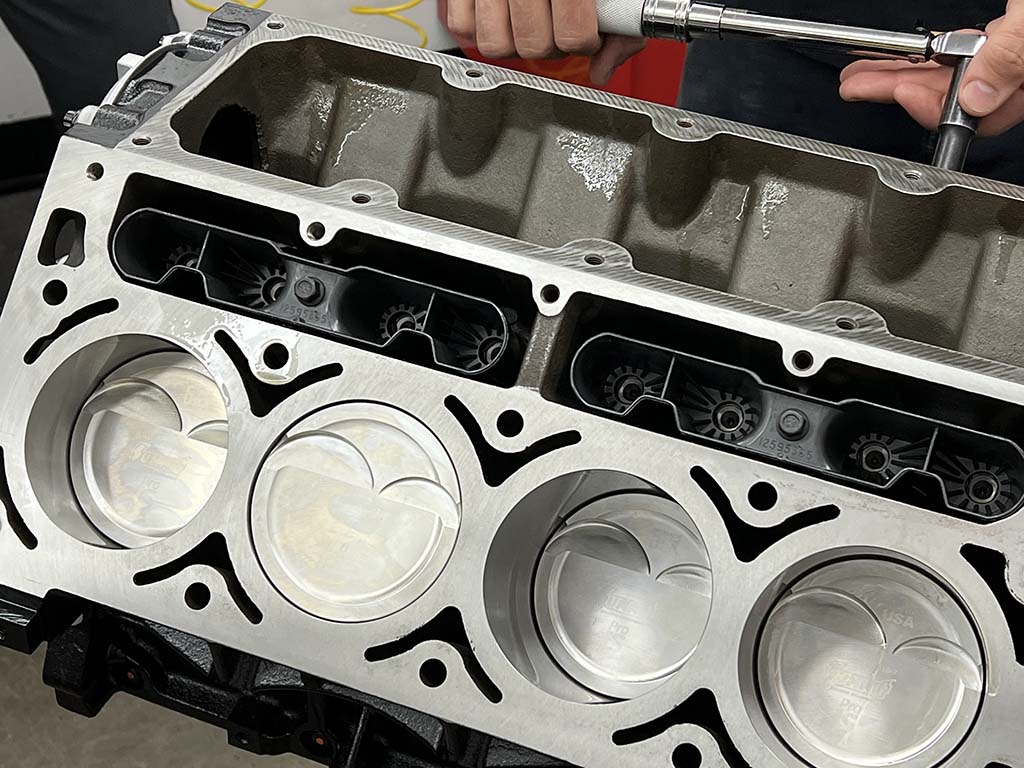
Work in progress table...you definitely have to remove a lot of parts to perform this job.
From my research and experience, LS Engine lifters seem to fail frequently for one of these primary reasons:
1. Aggressive lift
2. Aggressive lobe ramp
3. High spring pressure
4. Dirt, grit, contamination
I'll address each specifically next,
-Keep lift around/below .550-.580"
-Use a slow ramp profile, a daily driver lobe, not a 'racing' lobe
-Max spring pressure is around 130lbs seat, 300lbs open, only use single springs
-When the engine is open, it is surgery, do not touch parts with skin contact, skin will transfer contamination which nucleates failure point.
Especially Do not touch lifters or cam lobes with direct skin contact. When you receive the lifters and cam, oil them with new synthetic oil and new gloves, and then bag/wrap it sealed until installation. Do not allow them to sit in the box nor should you remove them and touch them with your skin contact.
Now, an example combination I know to be reliable from experience,
PAC1218 + TFS30602001
This spring and cam meets all of these requirements.
This cam+spring combo is good to around 800rwhp for LS1/LS2 applications and will ensure max reliability for daily drivers
Summary:
If the goal is reliability, do not select 'racing' parts and profiles. Use near-OEM quality parts with as close to OEM stress as possible.
Also if you think the engine has had metal inside the oil system, get a new engine block and replace all oil cooler lines/coolers/fittings to prevent metal debris from contaminating the new parts. Do it right or do it again
Hence only thing that is keeping the lifter roller tracking true the cam log,and when the tray wears out, allows the lifter roller to rotate against cam surface to skid and wear out the two surfaces.
So you can either keep changing the GM plastic lifter trays as needed (means pulling the heads to get to them), can go with metal lifter block guides to keep the lifters from rotating, or can go with pair linked lifters to keep the lifter from rotating isntead.
As for HB, what did you expect to happen with Oem unit and the added drag pull on it, and that should have been changed out to pinned ATI HB, when the SC was installed on the car.
lastly, stock lower block is good for about 650 hp for extended periods under boost, can be pushed to upwards of 700+hp for a few seconds hits or two of boost ever few mins, but will not hold up to to that HP when you into long duration's of constant Boost hits over and over again for mins at a time. The crank is fine for up to 1Khp, but need to change out connecting rods and pistons that will be rated for that HP, and make dam sure you gap the pistons correctly, so they heat grow to go zero gap, bind on the cylinder walls, and just rip the heads off the pistons. Top ring in the .028" gap range, and lower ring slighty more.
Note, on forged high HP pistons, top ring groove is lowered, to give more meat between the it and the top of piston.
We had a lifter failure on cylinder # 8 on an LS2 with a BTR Stage 3 cam. The car only had 40k miles, and the cam had been in it for much fewer miles than that.
After inspecting the lifter and tray, it was clear the lifter had rotated in the tray at some point, which ground it down flat. It was back in the correct position when we removed it, but it had already worn down, seized, and destroyed the cam. It failed while idling, was noticed immediately, and the car was shut down. But it still damaged the cam.
IMO, the factory lifters and any lifter tray style lifters are not going to be reliable in a cammed engine. The additional stress on the lifters will cause it to rotate in the tray at some point. Not going to link bar lifters when camming an engine is going to cost you a lot more money in the long run.
We swapped over to Johnson link bar lifters. Now that point of failure is no longer possible.
Or you can just use a near-OEM lift cam with a slow OEM-like ramp rate and the factory lifters and trays work just fine.
The problem isn't the trays its the ridiculous spring pressure and fast ramp rates putting stress on the valvetrain that ruins the weakest link.
Stop putting ridiculous heavy springs and high lift cams in an LS engine for no reason. With forced induction sub1k rwhp there is absolutely no reason, no excuse to do so.
People only do it because copy and paste , no thinking. So what if boost pressure is an extra 2 or 3psi? At least the engine can survive 250k instead of 40k
Again ask yourself, why do you want all that pressure and such a aggressive cam? Power is limited by the compressor, not the cam. You can make the same power on a stock cam it just takes more boost and a little bit of spring. Way more boost though. The trick to getting boost way down is duration, not lift, not spring pressure, not aggressive profiles. Spring pressure is for RPM, racing, 7k 8k 9k+ rpm all the time then you need a strong spring to close the valve at high RPM for many racing events, and those springs get changed frequently, well before 40k miles. If this is a daily driver sitting in traffic and fooling around on the street many may see that kind of RPM less than 0.11% of the time, making it a 99.89% poor decision to use that kind of camshaft in that type of vehicle.
I apologize in advance for replying to an old message but I'm afraid someone is going to find this thread from a Google search and not be aware of how hilariously asinine everything posted by this person is! Don't get fingerprints on the camshaft or touch the lobe? Really? Then he implies people are doing things wrong by increasing spring pressure on a boosted application. A boosted application requires more spring pressure but a hydraulic roller LS has less spring pressure than most engines on the road! There are dohc engines with more spring pressure than we run and obviously two valves share the pressure. I love it when guys engage in conversation about hot rodding and chastise everyone involved for hot rodding! I can't make myself comprehend why those who don't know anything about a subject will offer their advice.. Their WAY OFF BASE, inaccurate advice..
I apologize in advance for replying to an old message but I'm afraid someone is going to find this thread from a Google search and not be aware of how hilariously asinine everything posted by this person is! Don't get fingerprints on the camshaft or touch the lobe? Really? Then he implies people are doing things wrong by increasing spring pressure on a boosted application. A boosted application requires more spring pressure but a hydraulic roller LS has less spring pressure than most engines on the road! There are dohc engines with more spring pressure than we run and obviously two valves share the pressure. I love it when guys engage in conversation about hot rodding and chastise everyone involved for hot rodding! I can't make myself comprehend why those who don't know anything about a subject will offer their advice.. Their WAY OFF BASE, inaccurate advice..
Weird because I have a doctorate in mechanical engineering and 27 years building and tuning turbocharged daily drivers for high mileage reliability applications and engines with over 250,000 miles turbocharged many 20+ years on the clock following advice .. ah well I can't actually take credit, see. I learned from experience, which came from engineers that designed parts for turbocharged engines over 25 years ago... for example Greddy and HKS offer valve springs for 2jz-gte and sr20det and rb26dett turbo engines with low spring pressure (relative to say, comp cams and brian crower springs, for the same engine which are almost double the pressure iirc) that enabled the high mileage for the valvetrain... Because they use ENOUGH spring pressure to get the job done and not any extra, a SLOW lobe for control and LOW lift for minimizing wear/tear. The spring must complement the cam lobe and the low lift protects the hardware - this is the major concern for all engines, fast ramps fast lobes that require excessive spring pressure - It isn't the forced induction causing the problem its the lobe profile being jacked up as fast and high as it can go which calls for higher than necessary pressures and ruins the lifters in a LS V8 engine application and is completely unnecessary in hobby level applications. The key to longevity is LOW pressure and SLOW ramp rates on the lobes which can allow smooth excellent valve control for high rpm reliability. This is one critical aspect how to keep an LS and any other engine together with long term reliability turbocharged applications.
Here is an example I use frequently for LS turbo apps so you can get numbers. TFS30602001 and PAC1218. This cam and spring complement each other seemingly well, low enough pressure to enable 100 to 200k miles of reliability. SLOW ramp rate on the cam lobe profile for valve smooth control. LOW lift and LOW pressure and SLOW ramps = Long lifespan and high valvetrain reliability. And I will use this cam for 600 to 800rwhp forced induction 27 to 33psi of boost pressure gasoline and alcohol frequently for 10 to 15 years before changing the springs as a routine maintenance near 100 to 140k miles I suppose but more wouldn't hurt.
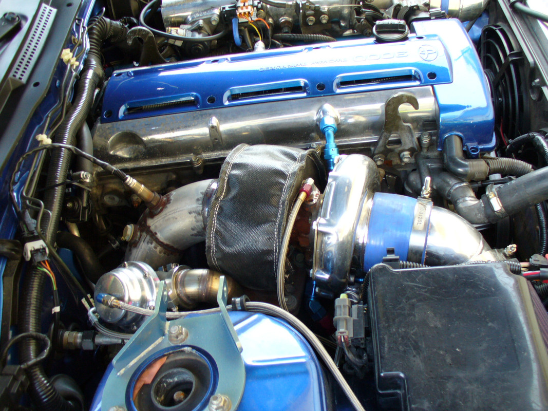
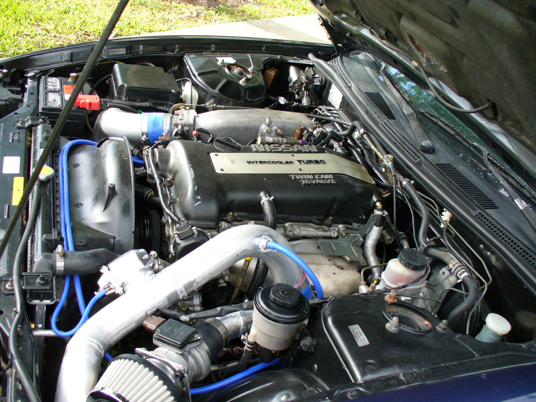
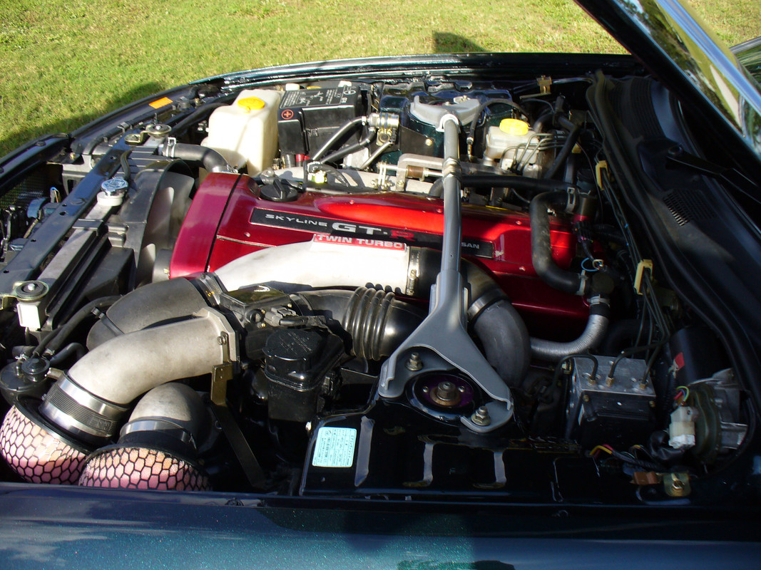
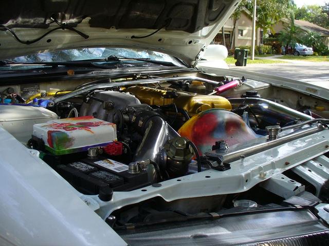
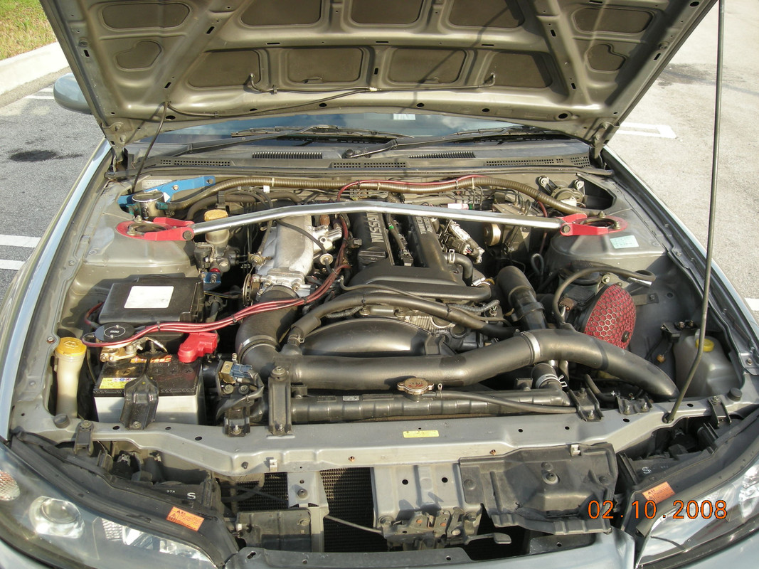
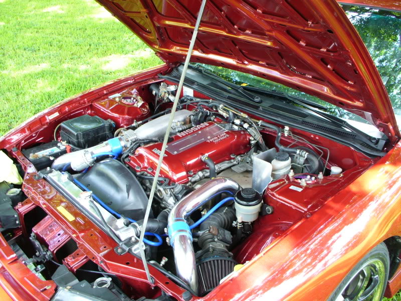
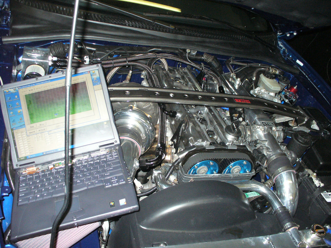
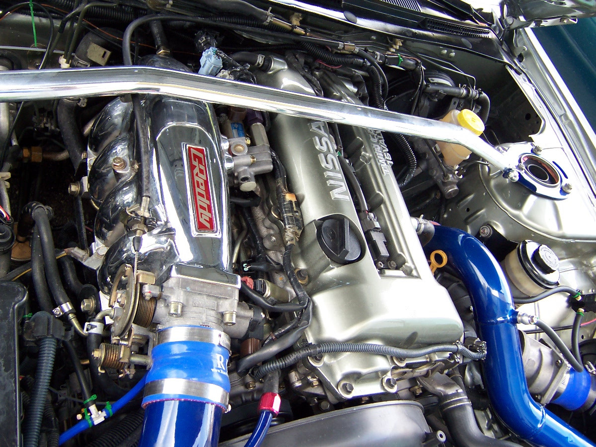
Here is some of my example engines, going back +25 years, LOW lift SLOW ramp 22 to 33psi of boost applications, high mileage capability daily drivers.
These are all roughly 150 to 250hp/liter turbocharged engines with low lift cams, light springs and slow lobes for reliability
I have complete build portfolio for almost all of these going back 25 years and same customers getting upgrades on the same engines for re-tunes decades later
The lessons are taken from engineers that figured this stuff out in the late 80's and applied it to the most famous turbo vehicles in existence such as Nissan Skyline and Toyota Supra
I learned those lessons and applied them back to the beloved LS applications and here we are, eyeballs crawling out of the wood work to scoff at the brilliance of Toyota and Nissan engineers meanwhile they can't keep a lifter happy and don't know why. If anybody could actually read what I write in the previous post they would notice I did not print any lift or spring pressure numbers. The term "low lift" and "light spring pressure" is relative to an UNKNOWN quality and quantity which is evidently sufficient given the products being offered specifically for forced induction applications for over 20 years used successfully by high end manufacturers!
The problem isn't the trays its the ridiculous spring pressure and fast ramp rates putting stress on the valvetrain that ruins the weakest link.
Stop putting ridiculous heavy springs and high lift cams in an LS engine for no reason. With forced induction sub1k rwhp there is absolutely no reason, no excuse to do so.
No numbers there! So how can you or anybody else possibly argue that my statement is incorrect or bad advice? If you have no idea what a "heavy spring" or "high lift cam" is based on that passage you cannot possibly argue any point. Maybe figure out what a heavy spring is and a high lift cam is first before trying to argue that the springs and cams I use for 25+ years successfully tuning sometimes 40 to 80 engines in a year somehow are "bad advice" even though they are all using sufficiently reliable turbocharger valve trains going hundreds of thousands of miles. Good day and good luck
Ah, totally forgot to do the dirty fingerprint discussion. The most important thing that nobody thinks of
This may come as a shock to many but hopefully it will wake you up
For this I will use copilot ai because there are so many interacting substrates it would take me wayyyy too long to make a reasonable explanation. I will proof read and adjust the responses to tailor to my liking and I've never used ai like this before in my life I usually just type everything myself but this one is... well you will see even I would have a hard time putting this together quickly enough for my time.
Let me start by saying people in the business of selling cams already have experienced this issue and relate to it to some extent
For example this Straub fellow from yellowbullet forum knows exactly what I am talking about, he is active forum vendor selling valvetrain items
Next I need to say something about what I do or did. I live in a lab environment where every bacteria is a source of potential contamination. The air itself must be purified and something as simple as fraction of human breath or touch ruins an experiment. Even without humans there is pollen and fungus and bacteria and water in the air at all times, particulate escalates from shoes and clothing and diffuses and dissolves into airborne droplets of water and debris spreading rapidly throughout a clean room environment and deposits to every surface. Most humans cannot comprehend the sheer complexity enumeration of such contaminants let alone their impacts. Furthermore the surface of objects is quite expansive and deeply carved with valleys and grooves and pits and microscopic crevices, even perfectly flat appearances are deceiving. For example if you place water into a glass beaker and boil it, the boiling bubbles can only form from pre-existing pockets of air trapped in microscopic air pockets in the irregularity of the glass(or whatever its made of). If there is no microscopic gouge in the surface with a trapped air pocket, the liquid water can never boil. Every surface no matter how clean and perfect and flat it appears likely contains innumerable tiny pockets, pits, gouges, irregularity, etc... where debris becomes trapped and 'seeds' future chemical and biological interactions.
This brings us to the surface of a camshaft lobe and what is placed there.
The cam lobe may look clean and flat but it contains many microscopic grooves gouges pits crevices and so on. Just because you can't see it doesn't mean it isn't there - humans especially mechanics seem to not realize this in so many cases and it leads to catastrophic results which is why I rarely recommend a cam swap or some internals work anymore for decades after seeing what is really happening during these installs when the engine is surgically opened up and filled with contamination to its microscopic parts. It is devastating to the metal materials when you make skin human contact or allow skin or biological-surface contamination to occur through any means such as leaving an engine part open to normal air for a day or two where pollen fungus debris can settle and make chemical contact to some exposed machine surfaces where the oil has been thinned out enough.
I cannot stress the importance of being surgically clean with internal engine parts anymore literally because I'm just sick of explaining it. So here goes the ai parts now. I will first break down what is inside a single fingerprint of a person who has been in contact with mechanical car parts, the surface area and then produce a step by step procedure for how we get to the ruined chewed up cam lobe we see in this thread from that starting point. Along the way I will input my human notes where needed to facilitate the explanation.
Start with the baseline human fingerprint
A. Biological (baseline human fingerprint)
• Sebum lipids
• Squalene
• Wax esters
• Cholesterol esters
• Triglycerides
• Free fatty acids (palmitic, oleic, stearic)
• Sweat components
• NaCl, KCl
• Ca�⁺, Mg�⁺
• Urea
• Lactic acid
• Amino acids (serine, glycine, alanine)
• Proteins (trace)
• Water
It is quite a list with some unknowns not shown. These biological contents deposit and adhere/disrupt the surface of a cam lobe even if your finger is absolutely clean.
What about mechanic 'fingers'
B. Shop‑environment contamination
• Metal fines
• Fe, FeO, Fe₂O₃
• Aluminum fines
• Copper/brass dust
• Stainless steel particles
• Abrasives
• Silica dust
• Aluminum oxide
• Garnet
• Carbonaceous material
• Soot
• Combustion carbon
• Graphitic wear particles
• Rust particles
• Fe₂O₃, Fe₃O₄ flakes
If you get any of that into your fingers and deposit to an internal engine part and think its okay well. @#*(& help you.
Next here are some automotive fluids that you may have contacted which can have impact in this
C. Automotive fluids
• Calcium sulfonates
• Molybdenum compounds
• Detergents/dispersants
• Grease
• Lithium complex
• Calcium sulfonate
• Moly grease
• Fuel residues
• Gasoline aromatics
• Diesel hydrocarbons
• Coolant
• Ethylene glycol
• Silicates
• Phosphates
• Brake fluid (glycol ethers)
• ATF (friction modifiers, esters)
And a few for the road
D. Environmental
• Road dust
• Tire rubber particles
• Pollen / Fungus
• Skin flakes
• Solvent residues (brake cleaner, acetone, toluene)
How large is a fingerprint?
A typical fingerprint contact patch is:
- 0.8–1.2 cm� for a light touch
- 1.5–2.0 cm� for a firm press
Let’s use 1.5cm� as realistic mechanic‑singlefingerprint to a cam value.
How many molecules are inside that single fingerprint to the cam? I want a physical quantity
This is where the ai really saves me time by calculating all of this. I checked some of it and the math looks good. I do teach math at university sometimes.
Lets start with a CLEAN fingerprint for somebody who has washed their hands from all shop-mechanic related debris
Holy cow look at that.
1E16 is 10,000,000,000,000,000 molecules of sodium chloride salt deposited by a single clean fingerprint.
I don't even know how to say that number out loud its enormous.
Look how much water makes physical contact - 200000000000000000 molecules of water to that cam lobe.
This stuff does not come off the cam lobe. You can wipe the cam lobe - maybe get half of it. But most of these molecules find surface imperfections and become permanent residents of the cam lobe. A thin oil film does not prevent dissolution, solvation, kinetic mixing / entropic distribution, and there is also surface interactions that HOLD these contaminants down, the metals and organics form polar and non polar interactions that increase their tenacity and pull them with time and movement into imperfections where nothing can dislodge them.
And so on. And this was the clean finger.
!@*&$ help you if your hands are dirty and you touch a cam lobe.
This next part is the play by play. Its sort of what I imagined in my head when I look at the pictures of chewed up cam lobes where the parts should all be compatible but the lobe roller chewed up. If you think about the cam material, the lifter roller, the pressure between them, and you've seen rollers and cam lobes come out of engines with 250,000 miles that look fine - you might start to wonder what went wrong in the lobes and rollers that don't come out looking fine since the metal materials seem to be up the challenge and experience nearly ZERO wear in factory assembled specimens with properly configured valvetrain components for millions of other engines. If we performed a statistical analysis I bet we would find that there is a massive confidence interval p << 0.05 for engines that were opened up by mechanic fingers for a cam installation which experienced dramatic lobe or roller failure in this fashion compared to factory engines using basically the same metal parts. And you could say 'well its the extra pressure or extra cam lobe rate or extra lift' and that is my originating point above - its not just ONE or TWO it is ALL of these things and they ALL need to be thoroughly understood and carefully thought about and mitigated as much as possible. The cleanliness, pressure, lobe ramp, and lift, all matter, all make a difference for reliability, and so parts need to be as CLEAN as possible, as LOW LIFT as possible, as SLOW as possible, and as LITTLE PRESSURE as possible, use enough but not EXTRA, and this is basically the ONLY WAY we can as hobby enthusiasts attempt to harness semblance of control over the longevity and reliability of our engines.
“Show me exactly how a fingerprint turns into a scuffed cam lobe, step by step”
Before the fingerprint matters, define the playground.
- Contact type:
Sliding/rolling line contact between cam lobe and follower (flat tappet, roller, bucket).
- Hertzian contact pressure:
approx 1-3{GPa} for a loaded valvetrain.
- Surface roughness:
Ra approx 0.05-0.2um for ground/honed cam lobes.
- Oil:
- Mixed/boundary at low RPM, cranking, starting.
- Hydrodynamic at speed, with oil wedge formation.
- Baseline protection (no contamination):
- Anti-wear film: ZDDP + other additives chemically react with the steel, forming a phosphate glassy layer (~50–200 nm).
- Oxide film: Native Fe-oxide passivation layer.
- Hydrodynamic film: Micron-scale oil thickness at speed.
The fingerprint doesn’t just “add gunk”; it locally modifies chemistry, roughness, and oil-film behavior in a specific patch.
^^ This is the big chemistry background moment that typical novices enthusiasts do not understand
2. Stage 0 – Deposition of the dirty fingerprint
You have a fresh cam lobe, then a dirty mechanic finger touches a lobe flank/nose.
- What gets deposited (locally on ~1.5 cm�):
- Biological:
Lipids, salts, amino acids, water.
- Shop contamination:
Metal fines (Fe, Al, Cu), abrasives (silica, alumina), soot.
- Fluids:
Engine oil, grease, coolant, fuel traces, brake cleaner residues.
- Geometric effect:
- Nonuniform film: Skin ridges create microscale “ridges and valleys” of contamination.
- Thickness variation: You might have tens to hundreds of nm of contaminants in some spots, less in others.
- Immediate surface implications:
- Local alteration of surface energy and wetting. Oil won’t wet uniformly. (This is easy for me to see working in a clean environment performing experiments I absolutely know this is some impact)
- Trapped contaminants: the fingerprint holds water, salts, and particles close to the metal surface. (we talked about this the main deposition and trapping within the irregular surface)
Think of this as laying down an inhomogeneous, reactive, slightly abrasive patch that the lobe will later run through.
3. Stage 1 – Chemical evolution before running
Time passes between assembly and first run: minutes to weeks.
- Moisture + salts (corrosion seeding):
- Chlorides + humidity start localized corrosion under the fingerprint.
- You get nanometer–micrometer scale pits and oxide thickening where sweat residue sits.
- Lipids and oil residue (varnish precursors):
- Squalene, fatty acids, fuel/oil residues begin slow oxidation, forming sticky, higher-polarity films.
- Dust + soot + metal fines embed in this sticky layer.
- Outcome of Stage 1:
- Slight micro-roughening from tiny pits.
- Patchy film that is:
- chemically different from base oil
- more polar, stickier
- loaded with particulate
You now have a chemically active, particulate-rich, microscopically rough patch sitting on what was a precision surface.
4. Stage 2 – First engine operation: interaction with lubrication
Once the engine starts and oil circulates, the cam-follower contact sees this patch under load.
4.1 Local disruption of hydrodynamic film
- Inflow region:
- Oil is trying to form a hydrodynamic wedge, but:
- Nonuniform wetting over fingerprint patch.
- Locally altered viscosity/chemistry (fingerprint lipids + degraded oils).
- Result: thinner local oil film over the contaminated patch.
- Mixed/boundary regime extension:
- Regions that should be hydrodynamic become mixed.
- The cam spends more of its rotation in conditions where asperities contact and additive films must carry the load.
4.2 Interaction with anti-wear films
- ZDDP competition:
- ZDDP tries to react with clean steel to form a glassy protective layer.
- But the fingerprint patch:
- physically blocks access in some spots (the fingerprint disrupts your protective films - forever)
- chemically competes with or alters the reaction kinetics
- Result: nonuniform or weaker ZDDP film exactly where you most want it.
- Abrasive inclusion in the boundary film:
- Metal fines, silica, and soot get embedded into:
- oxide films
- ZDDP layers
- organic varnish.
- These inclusions raise effective roughness and create local micro-cutting tips.
Outcome of Stage 2: you now have a zone with thinner oil, weaker anti-wear film, and embedded abrasives.
5. Stage 3 – Early wear and damage nucleation
Once this zone is repeatedly loaded, the damage transitions from “latent” to “active.”
5.1 Asperity-level contact and micro-cutting
- High-contact stress:
- Local Hertzian pressures in asperity contacts can exceed 1–3 GPa.
- What happens in the contaminated patch:
- Abrasive particles (silica, Fe oxides, soot aggregates) act like extremely localized cutting tools.
- Under each pass of the follower:
- Asperities plow, cut, and fracture the surface.
- You get micro-grooves aligned with sliding direction.
- Tradeoff with ZDDP film:
- ZDDP glassy layers can be protective but also brittle.
- Abrasives crack and spall these films.
- That leads to bare steel exposure, which re-oxidizes and reacts again, consuming additive.
5.2 Micro-pitting and stress concentration
- Corrosion pits from Stage 1 now see:
- Cyclic Hertzian loading.
- Sliding contact.
- Micropit evolution:
- Small pits act as stress concentrators.
- Repeated load cycles deepen pits and create subsurface cracks.
- Cracks can link up beneath the surface, leading to micro-spalls (tiny chunks of material detaching).
5.3 Debris generation and “self-feeding” wear
- Generated debris:
- Tiny steel particles, oxide fragments, fractured ZDDP film, and varnish flakes.
- Self-amplifying loop:
- New debris gets trapped in the fingerprint patch region.
- This debris further increases local abrasiveness.
- Wear rate in that patch accelerates with time.
At this stage, you can often see:
- Dull, slightly frosted patch on the cam lobe.
- Very fine directional polishing marks or micro-scratches in the contaminated region.
6. Stage 4 – Progressive roughening and mixed/boundary dominance
As damage accumulates, the surface roughness and local lubrication behavior change more dramatically.
6.1 Roughness growth
- Local Ra increase:
- From ~0.05–0.1 �m up toward 0.2–0.5 �m or higher.
- Consequences:
- Even with clean oil later, the rough patch maintains:
- Lower effective film thickness margin.
- More asperity contacts.
- ZDDP film regrows unevenly and keeps getting fractured under load.
6.2 Heat and boundary film breakdown
- More frictional heating:
- Increased asperity contact → more localized heat.
- Thermal effects:
- Local flash temperatures rise, which:
- Accelerates oil oxidation (varnish/sludge formation).
- Degrades boundary films.
- You can get brown/blue discoloration in severe cases from tempering or oxide changes.
The surface in this region transitions to a persistent hot spot with poor lubrication and unstable films.
7. Stage 5 – Macroscopic scuffing
Scuffing is the point where the contact goes from “controlled wear” to “surface failure.”
7.1 What is scuffing in this context?
- Definition:
A rapid, localized breakdown of the lubricating film with direct metal-to-metal contact, causing severe adhesive wear, tearing, and surface transfer.
7.2 How the fingerprint patch triggers scuffing
- Lead-in conditions:
- High local roughness from prior wear.
- Depleted additives locally (ZDDP largely consumed or fractured).
- Abrasive debris still circulating in the patch.
- Elevated local temperature from friction.
- Trigger event:
- A transient: cold start, high load, low RPM, poor oil, or a slight misalignment.
- The already vulnerable patch cannot sustain an oil film.
- Full boundary contact over a larger fraction of the contact patch.
- Scuffing progression:
- Steel asperities microweld under high pressure and temperature.
- On separation, tearing and material transfer occur.
- Each pass enlarges the scuffed area; the surface geometry worsens.
- This leads to:
- deep score marks
- pulled material “smearing”
- visible galling or tearing on the lobe and/or follower.
At this point, the original fingerprint has long since disappeared, but the damage cascade it seeded has permanently altered the contact.
Its hard to imagine 200000000000000000 of something but that number is real and its in a single fingerprint and its going to deposit permanently some things that disrupt the protective properties of fluids and leads to disaster. Do not touch open exposed engine internal parts with skin contact. This includes spark plugs. Have a nice day
The cam duration and valve timing make the radical potato noises, and have zero impact on reliability(as long as the valve doesn't smack the piston on the first rotation).
The lift, ramp rate, and spring pressure, all which impact reliability, have almost nothing to do with making the cam 'lumpy'. Actually having a very fast ramp should decrease the lumpyness because the valve is being snapped open and shut more quickly within some range giving less time for cylinder flow shenanigans. The reason my low lift cam makes the engine sound like that is because air is leaving some of the cylinders after it enters them as the valve is hanging open longer than usual due to it's duration - duration does not impact reliability only low speed performance hence the idle getting all unstable. When the air leaves the cylinder it rises pressure in the plenum which can be seen on the map sensor if sensitive enough as a subtle slight momentary increase. This slight rise of pressure changes the cylinder fill in the next cylinder to fire. And there is also the momentum of airflow being stopped or flowing in reverse via runners which causes air to stall in the plenum or other nearby runners which subtracts cylinder fill from those in a repeating fashion - which depends on the intake manifold design to some extent. So some intake manifolds like my LS1 there create a harmonic 'stable' lope sound where the same cylinder(s) are repeatedly starved at idle which gives us that consistent exhaust noise like a repeating decimal. Other intake systems and cam profiles cannot organize the airflow distribution like that and get a wild unstable idle without any noticeably repeating frequency.
In short. The lopey lumpy sound is mostly based on duration and valve specific timing (advanced, retarded valve events and how long that stay open) which does not impact reliability. Get as lumpy as you want. But if you want the engine to be reliable, have good valve control at high rpm, and keep the lifters and valve guides happy, then you will reduce the lift, spring pressure, and opening/closing ramp lobe rates as much as possible or feasible in your application. Hobby level installations have no business being high lift high pressure fast ramps - its your personal property, not a sponsership vehicle. That extra lift ramp and spring might give what an extra 20 or even 50hp but you can make an extra 400hp without it using forced induction and without ruining the engine and also where is the race worth winning to ruin the engine over? In a level playing field like nascar it makes sense to jack the compression lift lobe fuel etc... up as high as possible because that is a level playing field with sponsors and an engine you intend to destroy in the race, fine. But at a hobby level you are not a nascar level playing field, it is an unlimited class for most of us with no race to win and no money coming in for winning that race so by what logic would you ruin your engine for the extra 20 or 50hp ?


.jpg)