When you click on links to various merchants on this site and make a purchase, this can result in this site earning a commission. Affiliate programs and affiliations include, but are not limited to, the eBay Partner Network.
I posted this on the general board, but it was suggested to post it here.
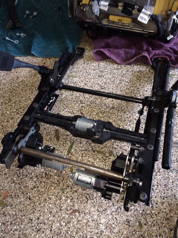
I need help. I'm installing C7 seats into my C3. The car's got a 480hp LS3 and all kinds of other mods. I picked up some C7 seats and I'm installing them. I've already determined I will need to remove the bottom C7 seat rails. This is a one piece unit that adjust all of the location adjustments on the floor.
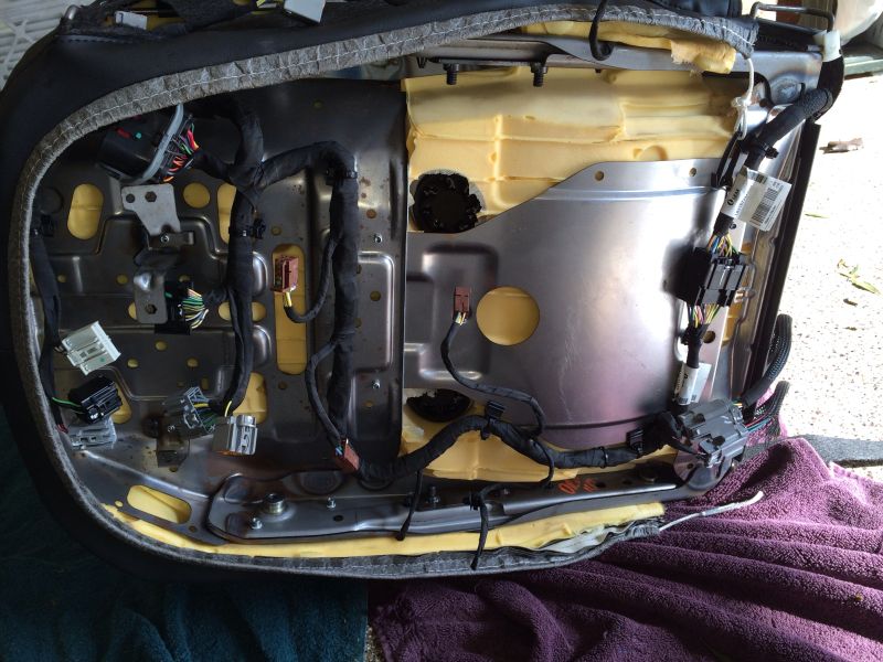
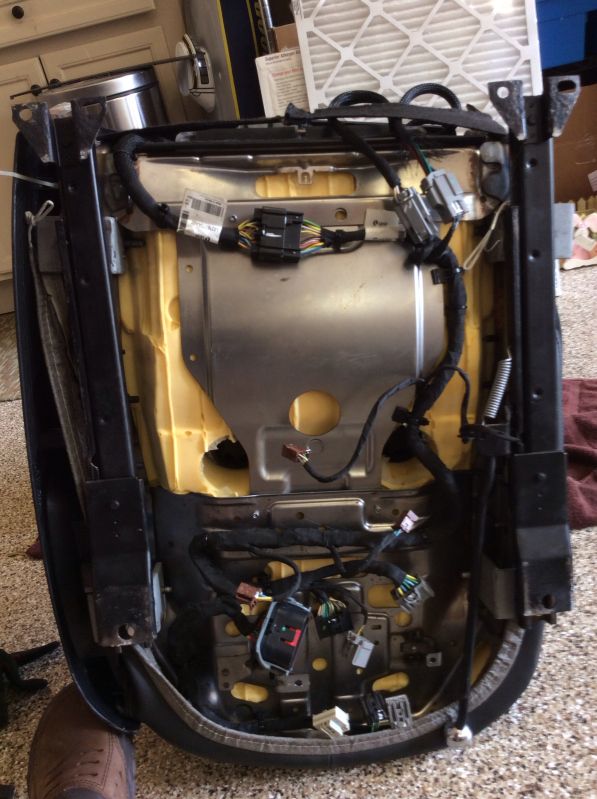
Seat without the seat rails (4 bolts holding it on)
And now with my seat tracks installed.
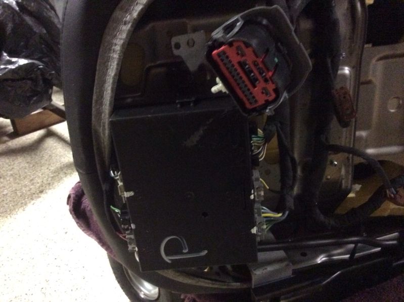
The help I need is figuring out the wiring on the seat so that I can still actuate the seat recline, air cooling fans, and lumbar control. As you can see on the seat bottom, there are all kinds of electrical connectors. I need a wiring diagram or shortcuts to get me to the finish line. I've done this before on my C2 with C5 seats. That was easy because their were only a few wires. This seat is very complex and I don't want to screw it up. The seat back is locked in a downward position right now and won't recline until I get power to it.
Any help is appreciated. I'm assuming I'm going to need custom switches for the fan control, but the side adjusters should work fine for the seat functions.
Most important first off is getting the seat to recline so I can custom fit the seats in the car. I've set them up in the car, but until I can get a recline, I can't truly see how well they are going to work.
Now I need a translation. I'm not as skilled as I may appear. I need to know where do I put power so it will work. Take a look at the pics There appears to be a main connector (large horizontal length) that looks to be the main source. Where do I connect power?
I can't seem to figure this one out. I'm no wiring expert so I need help. I've got my seat and a battery on a bench. I'm trying to just get the seat back to recline.
I know I've got to get power to the switch and the motor, and get some sort of ground.
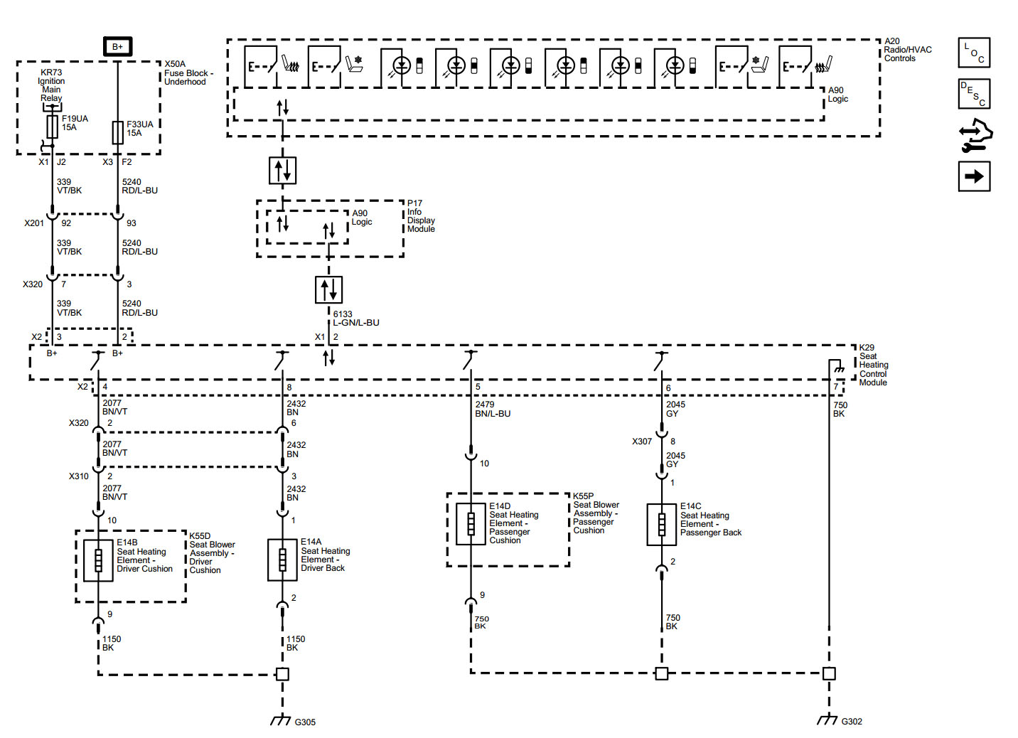
If you look at the first diagram, in the top left corner are two terminals labelled B+ . That's the 12V DC - it goes through some fuses and enters the K40D seat memory control module at connector X1, terminals X1 and X2.
I'd start with fused 12V connected there, and ground at connector X2 terminal 5.
The fact that there are numerous Data Control terminals suggest to me that there may be lots of issues with this plan. It gonna be tricky...
Keep an eye out for smoke, (no expertise intended or implied on my part)
You will only get the power features to work on the seats, basically the movements of the seat.
Unless....
You have the BCM and possibly ECM from the donor car the seats came out of. The memory seat module controls all other functions without the BCM and the switches not going to work.
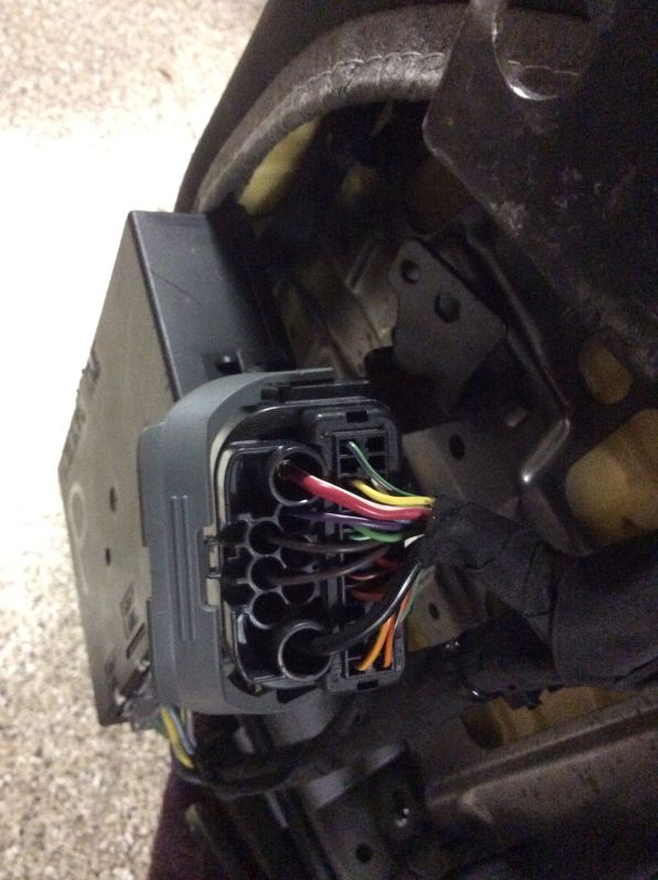
Get your power & ground they should work, if your not sure which wires show a detailed picture of the connector should be the 2 thicker wires in the connector.
another question...should I be getting rid of the side airbag? Someone told me to be very careful because I could set it off and seriously hurt myself.
For the seat fans, you will literally need to just do a power/ground setup, but be sure you're matching the voltage on the fans. I'm not sure if the fans are 5v or 12v. If they're 12v, you can essentially rig an SPST toggle to turn them on and off as you'd like.
As for the airbag comment, the person who told you that was correct. What I posted was essentially to be used on a professional level. You can seriously injure or even kill yourself if you trip one of the airbags while 'testing' wiring. Please be careful.
I have a set of seats I'm trying to retrofit into a 67 corvette. My goal is to make them fully functional - motion, heaters, and ventilation. I've connected 12V + to the terminal with the Red/white wire in the connector show in Post 12. I grounded the heavy gauge black wire on the same connector. Results were no motion. Any suggestions were to go from here to achieve motion? Is there a pin out list that shows what each wire in that big connector in Post 12 is for?
Air bags are blown, so no risk there.
I can simply hook up a toggle switch for the ventilators.
Perhaps a simple switch for the heaters as well, but no sure if there is a high or low feature built into the existing controls.
I tried jumping power directly to the motor that controls up/down front of the seat. I followed the following schematic with 12V+ to the red/white wire then alternated 12V-(ground) between the L-Gn/BN and L BU/VLT wire. I connected nothing to the BN/WH. Motor didn't move. I suspect 12V- should go to the BN/Wh wire as well, but wasn't sure what the device with the ? mark on it was supposed to be, maybe a resistor? Any ideas?
I tried jumping power directly to the motor that controls up/down front of the seat. I followed the following schematic with 12V+ to the red/white wire then alternated 12V-(ground) between the L-Gn/BN and L BU/VLT wire. I connected nothing to the BN/WH. Motor didn't move. I suspect 12V- should go to the BN/Wh wire as well, but wasn't sure what the device with the ? mark on it was supposed to be, maybe a resistor? Any ideas?
update on this project? I am currently trying to make c7 seats work in my c5 and i am hitting a lot of walls with this wiring
Post a picture of the large multi wire connector and I can help. I figured it out but its been 2 years and recall one ground wire and 2 hot wires are needed to make them work,