When you click on links to various merchants on this site and make a purchase, this can result in this site earning a commission. Affiliate programs and affiliations include, but are not limited to, the eBay Partner Network.
Okay I understand the concept is NEW but it is not very difficult. I will give examples to help you see how simple this really is.
First, yeh olde blown engine and excessive vent tube example, for wet sump engines using PCV valves (dry sump does not always have a PCV valve)
Notice the PRESSURE is a number, like tire pressure. You can measure tire pressure, right? Then you can measure crankcase pressure.
Look 0.5" Hg is PRESSURE. 0.5" Hg = -0.245PSI
Inches of mercury is a vacuum measurement that we can express in PSI.
The longer the 'venting' tube, the more energy required to move air molecules within that tube, the higher the pressure difference will become- since for all sub sonic flow exiting at atmospheric pressure, MUST exit at Atmospheric pressure. This is a fluid mechanics undergrad concept for freshmen engineering.
Similarly, we can use this example showing the same affect, for engine air pump (breathing = power)
Both the crankcase evacuation, and engine intake manifold, represent a pressure different from atmospheric at some time interval, and subject to flow rates that ultimately depend on the atmospheric supply for air molecules and pressure differences. They are both subject to the same universal natural laws with respect to energy, gas kinetics, turbulence, separation, etc... these are terms which help us visualize and understand fluid flows. Air is a fluid, water is a fluid. Both water and air behave similar under some circumstances, but differently in others due to density difference.
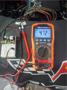
Next, a real world example measurement technique using 1-bar map sensor.
Here is 2009 C6 Z06, 40k ish miles. Stock motor internals, intake, exhaust.
A helpful member here supplied this data and there is more to come.
Connect map sensor to engine crankcase, shown
Reading with engine *OFF*
Reading with engine*ON* at IDLE:
Around 0.20v Drop from 1-bar map sensor is approx -0.6 to -0.8PSI of pressure drop at idle. Our target for performance engines is 0.5" to 3" Hg which is roughly -0.25psi to -1.5psi , so this is well within range. We can fairly assured there is no leak or interference from any modifications or issues with the engine, it seems healthy.
Next it should be measured at WOT but he has not had a chance to do this yet.
Here is a video how I Setup to measure crankcase pressure for the above experiment, except on a turbo wet sump vehicle (same setup, different engine/car).
I've measured around 20 different types of engines, ranging from honda, toyota, nissan, subaru, mazda, ford, chevrolet, whatever. All OEM use a similar technique to draw crankcase pressure down at WOT which depends mostly on the air filter. In dry sump applications it depends more on the scavenging pump, although the air filter still has some influence. In any case, if you learn to take this measurement, like tire pressure, you can begin to piece together the puzzle of influence which relates pressure, flow, velocity to oil droplet formation, oil condensation, oil control.
I think alot of people do not realize that oil should facilitate to exist as a gas state, not a liquid, in PCV flow. When blow-by gas enters the crankcase it very hot, fast moving gas, it contains some oil, gasoline, and other carbon byproducts related to oil and gasoline plus anything that passes the air filter and gets into the crankcase. Gasoline and oil associated closely, they are nearly identical configurations of hydrocarbon alkanes, carbon chains which hydrophobically interact. Oil can be broken down into gasoline provided the correct fracture points- although its flat configuration leads it to become a very low octane gasoline, perhaps 0octane (n-heptane) or close to 0.
The branching of hydrocarbons influences the steric hindrance- the ability of the hydrocarbon fuels to pack tightly and the availability of electronic configurations to approaching collisions of oxygen radicals which seek to forward chemical reactions.
Sorry, Its all chemistry at this point. You need be able to visualize an oxygen radical attacking a hydrocarbon chain to understand where fuel octane comes from in gasoline. Otherwise you cannot connect that idea to the concept of oil as a fuel, as a gas state, as an octane reducer, easily.
In any case. Oil as a gas , can become a liquid. Simply cool it, slow it down, condense it, like water. Imagine water vapors flowing in a tube. If you want them to turn to liquid, you would cool and slow them down, and then collect them.
In an engine, if this happens anywhere between the crankcase and intake manifold, the oil becomes a liquid deposit somewhere, such as the intake valve, or throttle valve. When the liquid is exposed to air (flow, or stagnant) the light chains of oil will leave, just like with gasoline sitting in a vented container such as a carb, causing the leftover oil to be mostly formed of long, sticky, closely associated chains, deposits, 'varnish'?, residues which are difficult to remove and may stick down somewhere leaving a deposit which can gradually harden.
A goal of PCV hoses/tubes is to prevent these deposits, to prevent condensation of oil and gas molecules, to prevent them from slowing down, prevent them from cooling. This is why we want very SHORT and Small diameter tubes leading from crankcase to intake manifold suction, these maintain high velocity gas flows, which helps the oil remain suspended as a gas, which allows it to enter the intake manifold and enter the cylinder without condensing on valves or causing puddles inside the intake manifold. Some gas state oil molecules of course impact the valves, cylinder walls, throttle valve, etc... metal materials which benefit from such 'dry lube' sort of coating over time. The deposits begin to form when the oil is able to collect heavy hydrocarbon chains due to excessive cooling or low velocity for some reason, such as unwanted external enlarged PCV hoses which reduce gas velocity.
....
Air is a fluid, water is a fluid. Both water and air behave similar under some circumstances, but differently in others due to density difference.
Sorry did not take the time to read all your theoretical diatribe. But when this post popped up on my email, I quickly saw this statement at the end! Hmm, major difference is air is compressible! My business involves small gas pressure differences, choked flow etc. Could not let it stand.
Second with all the theoretical examples you are missing a point. Dry sumps pull air with the oil and can cause a vacuum NOT pressure in the crankcase. GM quantified the "vacuum" in the LT6!
I love your question. As a chemistry/math tutor & PhD mechanical MS/BS bioengineering/chemistry/biological science/mathematics it is quite clear to me by inspection the behavior of gas kinetics what seems to elude practically everyone.... it is not a secret? It is really a conceptualization from a chemistry book, that is the 'secret'.
First the purpose of pcv, PCV is engine cleanliness
The PCV system is intended to provide engine cleanliness for the high mileage and health of an engine, the PCV system prioritizes the engine crankcase components (oil orifice quality, lubrication, bearings, oil flow, oil control, ring function, ring cleanliness, deposit formation, and other cleanliness and oil control aspects) above all else. Originally seen as an emissions device, PCV has evolved into an engine cleaning, seal function and oil control feature.
Gas kinetics
Gas density, velocity, and partial pressure are definable features inside the engine crankcase related to engine cleanliness.
Gas molecules near room temp move 500 to 1000mph, colliding constantly with each other and the wall of their containers. This is why tires stay inflated at rest.
Warmer = faster, you drive the car tire pressure goes up due to gas heating. Higher pressure = more elastic collisions per unit time.
Oil molecules originally as a gas state are forming liquid droplets in crankcase gas due to collision with each other and their container, oil sticks to itself as a gas or liquid as they interact hydrophobically (hydrophobic interactions) and high gas density facilitates large oil droplet formation. Oil droplets forming under high pressure scalars with low kinetic energy velocity components gives rise to even larger droplets per unit time.
If crankcase pressure rises for any reason- excess blowby, leaking valve cover gasket, improper air filter pressure drop, gas density increases with crankcase pressure causing large oil droplet formation and coalescence, oil begins collecting to tube walls, flow paths, etc... more rapidly
Oil separation efficiency
PCV primary oil control point is crankcase pressure (Gas density) and oil separation (utilizing kinetic energy distributed adequately) and additionally a cleanliness aspect is partial pressure (dissolved gasses which are able to enter and leave engine oil over time are based on pressure).
The OEM oil/air separators are very good, even since the 80's pretty good. But there is no stopping high gas density which carries large droplets of oil from flooding into and collecting in the separators and invading subsequent lines and manifolds. An OEM air/oil separator IS a catch can, it is intended to catch oil and force oil back to the crankcase by taking advantage of gas kinetics (kinetic energy of the gas moving with a specific direction) which is a vector quantity, unlike pressure which is a scalar and has no direction.
The pressure scalar is a system wide collision and diffusion component of the pcv system and engine crankcase, while the kinetic energy is a velocity vector component of the pcv system & crankcase, and the two must be treated separately when comparing flow of gas within the engine crankcase (by the engineers or us when we modify the system) and their influence respectively.
Without sufficient kinetic energy (too much added crankcase volume or reduced input energy due to improper air filter pressure drop or inadequate vacuum pump operation for example) there may be insufficient oil separation by the OEM separator, leading to oil aspiration and baffles filling with liquid oil, oil inclusion (oil going places it should not be able to reach if the system was setup properly).
A pressure scalar will not work well to perform oil/air separation, the pressure scalar has no direction and forces gas molecules to collide all directions at once for a net velocity of zero, oil can combine to form large droplets and collect while it has no significant direction magnitude or moving very slowly , time to "condense" oil gas to liquid droplets in the gas suspension or onto surfaces. Additionally a high pressure scalar will force oil into engine seals causing oil leaks, and it will impact piston ring performance, forcing early ring switching and potentially causing ring flutter and oil accumulation of the ring pack.
Notice the axial force of crankcase pressure is a component of piston ring sealing, piston ring function, piston ring tension. A high gas pressure scalar in the crankcase will reduce ring function leading to additional blowby which causes even higher pressure scalar within the engine crankcase.
Thus the PCV system is not only an oil control feature, and engine cleanliness, it also serves to protect piston ring function and reduce blowby, improving the efficiency of the engine cylinder.
My opinion (discussion)
If anybody has gotten this far and realized that PCV is actually quite complex- surely you must also realize the extent of the knowledge from which the original engineers must draw from to design such a critical and effective evacuation for a modern high quality engine. If you trust them to design the engine, you buy the vehicle, to give you something so incredibly complex and powerful, -this work of art meant to be thrashed while maintaining reliability- but then doubt they can effectively design the oil system and think that adding a small tin can to the side of such an extravagant device is necessary? Why stop there, why not doubt the crankshaft bearing and change those as well? why not the guides in the head? Why not the timing chain, replace it with something superior? Why do people suspect just the PCV system but assume all the other parts are working well enough to be left alone. Something strange, marketing perhaps?
When you see a billion dollars of engineering & computer modeling and then people want to stick a $1 container inline somewhere because they think that they know better than a billion dollars of engineering... I mean. I'm not saying catch cans are bad- they can be utilized effectively in some situations for typical engines with wet sumps that have been turned up to 3x to 4x factory output. But this isn't a typical engine... this is a CX dry sump engine we are talking about here, the epitome of PCV and oil control features, not some corolla or honda engine that needs holes drilled in the baffles to facilitate drainage because you've increased the redline to 9k rpm and tripled the power output using custom forced induction and nitrous components.
Should it shock us that metal parts desire oil lubrication? The throttle valve is made of metal, usually. It will rapidly oxidize when exposed to constant flow of oxygen. Even aluminum will oxidize over time, disintegrate. Turbocharger compressor wheels desire lubrication. Valves- lubrication. A small bit of oil film is desirable. The OEM engineers know how much oil is leaving the crankcase and they have tuned the mass of oil such that it will maintain the quality and longevity of these components, be it throttle valve, compressor wheel, intake valve. If you prevent the oil from reaching the throttle valve and take the vehicle to 200k miles I can assure you there will be deleterious consequences, it may stick, or it may deteriorate. Unless you are manually lubricating it at maintenance intervals. I always remove my intake tube and WD40 the throttle valve, clean it with a towel and a pick, get the bit of debris or grit out of it. Same thing with turbo compressor, it needs occasional WD40 or similar to maintain a protective oil film. Metal materials everywhere in the world will crumble to dust if some lubrication is not supplied.
Originally Posted by Kingtal0n
The air filter is by far the best example for this. "upgraded" air filters are often the first thing we do as a novice to our performance vehicle... and generally this is the worst possible thing you can do without proper education and experience of how it will impact the engine health.
If the filter quality is insufficient it will enable trash and debris to accumulate in the engine, which ruins the cylinder, embeds materials to the head and deck (or intercooler/turbo) , wrecks the piston oil seal and piston materials. 'dirt' sand, pollen, fungus, dust, debris, gets into the oil system and facilitates deposits and carbon conglomerates. What is pollen and fungus made of? Why, the materials of life, such as Iron, Molybdenum, Sulfur, Carbon, Chlorine, Potassium, Sodium, etc... pretty much the entire upper half of the periodic table is inside fungus and pollen. If I asked you, "would you like to send iron, potassium, sulfur, chlorine, sodium, etc... into your engine today?" Would you say it was okay? Of course not. And yet people don't think twice about filtration particulate quality which directly impacts the ability of an engine oil system to remain clean and clear and the function of the piston rings.
Next, we have the PCV pressure drop. Not a big problem for dry sump engines which utilize pumps to drive most of the pcv action... but this is a major source of frustration and confusion for wet sump applications where people do not realize the importance of the AIR FILTER in terms of Crankcase Pressure PCV action.
At wide open throttle the only place to find a suction is between the filter and the throttle valve/turbo. All engines from all OEM manufacturers in the world provide a pathway from this region which leads to the crankcase. However, if you remove the air filter or 'upgrade' the filter to the point where it is 'invisible' (flows too freely) there will be no pressure drop in this region and subsequently no PCV action at wide open throttle, causing crankcase pressure to rise and oil begins to blow into the intake manfold and out of every engine oil seal over time.
Originally Posted by Kingtal0n
Okay I understand the concept is NEW but it is not very difficult. I will give examples to help you see how simple this really is.
First, yeh olde blown engine and excessive vent tube example, for wet sump engines using PCV valves (dry sump does not always have a PCV valve)
Notice the PRESSURE is a number, like tire pressure. You can measure tire pressure, right? Then you can measure crankcase pressure.
Look 0.5" Hg is PRESSURE. 0.5" Hg = -0.245PSI
Inches of mercury is a vacuum measurement that we can express in PSI.
The longer the 'venting' tube, the more energy required to move air molecules within that tube, the higher the pressure difference will become- since for all sub sonic flow exiting at atmospheric pressure, MUST exit at Atmospheric pressure. This is a fluid mechanics undergrad concept for freshmen engineering.
Similarly, we can use this example showing the same affect, for engine air pump (breathing = power)
Both the crankcase evacuation, and engine intake manifold, represent a pressure different from atmospheric at some time interval, and subject to flow rates that ultimately depend on the atmospheric supply for air molecules and pressure differences. They are both subject to the same universal natural laws with respect to energy, gas kinetics, turbulence, separation, etc... these are terms which help us visualize and understand fluid flows. Air is a fluid, water is a fluid. Both water and air behave similar under some circumstances, but differently in others due to density difference.
Originally Posted by Kingtal0n
Next, a real world example measurement technique using 1-bar map sensor.
Here is 2009 C6 Z06, 40k ish miles. Stock motor internals, intake, exhaust.
A helpful member here supplied this data and there is more to come.
Connect map sensor to engine crankcase, shown
Reading with engine *OFF*
Reading with engine*ON* at IDLE:
Around 0.20v Drop from 1-bar map sensor is approx -0.6 to -0.8PSI of pressure drop at idle. Our target for performance engines is 0.5" to 3" Hg which is roughly -0.25psi to -1.5psi , so this is well within range. We can fairly assured there is no leak or interference from any modifications or issues with the engine, it seems healthy.
Next it should be measured at WOT but he has not had a chance to do this yet.
Here is a video how I Setup to measure crankcase pressure for the above experiment, except on a turbo wet sump vehicle (same setup, different engine/car). https://www.youtube.com/watch?v=0oRbfNPnHaI&t=5
I've measured around 20 different types of engines, ranging from honda, toyota, nissan, subaru, mazda, ford, chevrolet, whatever. All OEM use a similar technique to draw crankcase pressure down at WOT which depends mostly on the air filter. In dry sump applications it depends more on the scavenging pump, although the air filter still has some influence. In any case, if you learn to take this measurement, like tire pressure, you can begin to piece together the puzzle of influence which relates pressure, flow, velocity to oil droplet formation, oil condensation, oil control.
I think alot of people do not realize that oil should facilitate to exist as a gas state, not a liquid, in PCV flow. When blow-by gas enters the crankcase it very hot, fast moving gas, it contains some oil, gasoline, and other carbon byproducts related to oil and gasoline plus anything that passes the air filter and gets into the crankcase. Gasoline and oil associated closely, they are nearly identical configurations of hydrocarbon alkanes, carbon chains which hydrophobically interact. Oil can be broken down into gasoline provided the correct fracture points- although its flat configuration leads it to become a very low octane gasoline, perhaps 0octane (n-heptane) or close to 0.
The branching of hydrocarbons influences the steric hindrance- the ability of the hydrocarbon fuels to pack tightly and the availability of electronic configurations to approaching collisions of oxygen radicals which seek to forward chemical reactions.
Sorry, Its all chemistry at this point. You need be able to visualize an oxygen radical attacking a hydrocarbon chain to understand where fuel octane comes from in gasoline. Otherwise you cannot connect that idea to the concept of oil as a fuel, as a gas state, as an octane reducer, easily.
In any case. Oil as a gas , can become a liquid. Simply cool it, slow it down, condense it, like water. Imagine water vapors flowing in a tube. If you want them to turn to liquid, you would cool and slow them down, and then collect them.
In an engine, if this happens anywhere between the crankcase and intake manifold, the oil becomes a liquid deposit somewhere, such as the intake valve, or throttle valve. When the liquid is exposed to air (flow, or stagnant) the light chains of oil will leave, just like with gasoline sitting in a vented container such as a carb, causing the leftover oil to be mostly formed of long, sticky, closely associated chains, deposits, 'varnish'?, residues which are difficult to remove and may stick down somewhere leaving a deposit which can gradually harden.
A goal of PCV hoses/tubes is to prevent these deposits, to prevent condensation of oil and gas molecules, to prevent them from slowing down, prevent them from cooling. This is why we want very SHORT and Small diameter tubes leading from crankcase to intake manifold suction, these maintain high velocity gas flows, which helps the oil remain suspended as a gas, which allows it to enter the intake manifold and enter the cylinder without condensing on valves or causing puddles inside the intake manifold. Some gas state oil molecules of course impact the valves, cylinder walls, throttle valve, etc... metal materials which benefit from such 'dry lube' sort of coating over time. The deposits begin to form when the oil is able to collect heavy hydrocarbon chains due to excessive cooling or low velocity for some reason, such as unwanted external enlarged PCV hoses which reduce gas velocity.
Sorry did not take the time to read all your theoretical diatribe. But when this post popped up on my email, I quickly saw this statement at the end! Hmm, major difference is air is compressible! My business involves small pressure differences, choked flow etc. Could not let it stand.
Second with all the theoretical examples you are missing a point. Dry sumps pull air with the oil and can cause a vacuum NOT pressure in the crankcase. GM quantified the "vacuum" in the LT6!
Maybe you should read all of it, as the use of vaccum in the crankcase is clearly discussed, as is what happens when you mess with that system and turn negative pressure into positive pressure.
Second, water is compressible. If it wasn't we wouldn't need brake/hydraulic fluid. Fluids are commonly referred to as incompressible, but they absolutely are compressible. Technically everything is compressible with the right pressure - just ask a black hole.
Hmm, yep what happens when you only think theoretically! For PRATICAL purposes water can be considered non compressible!
SIDEBAR
Reminded of a 2-year consulting effort as an expert witness. Although my field is welding and what my report/deposition were based on the issue included motors having carburetors with a built-in fuel pump. That versus the separate pump used by the welding generator that the plaintiff was suing for $650 million dollars for a wrongful death and a badly disfigured welder, saying the fuel delivery hose from the pump leaked!
Turned out one of the prosecutors' 10 expert witnesses was a professor from a prominent University and his 20-page report was very well written. In fact, read it fully (as got paid handsomely to do that. Case paid for my 2017 Grand Sport!) I learned something about this unique carburetor that in fact no one in our industry used for motor driven welders! Recall mentioning his excellent report to the defense attorney who hired me. He said, yep have run into him in prior cases. He writes well but has not been out of school since kindergarten and has no practical experience!
I appreciate anybody that asks questions and thinks critically. I wish to remind everyone that I can't think of everything in every post, I always leave things out because there is too much to list, and some things more important than others, and some things I just forget, I am human and make mistakes. There is always more to discuss, I just write so much already it becomes daunting task to cover every little thing, and I really don't like to text-wall on forums even though it seems that I will frequently, its just literally ten books and 25 years experience of information I am trying to squeeze into a tight space as this.
JerryU I appreciate you and everybody asking questions and thinking for themselves.
I would like to read something from book of engineering fluid mechanics ISBN9780470086391
page12
"The density of some fluids is more easily changed than that of others. For example, air can be compressed at moderate pressure with a consequent density change, whereas a very large pressure is needed to effect a relatively small density change in water. For most applications, water can be considered incompressible and, in turn, can be assumed to have a constant density. Air, on the other hand, is a relatively compressible fluid with variable density. However, at velocities much less than the speed of sound, the air density changes only slightly and the air can also be treated as incompressible. Incompressibility does not always imply constant density. For example, a mixture of salt in water changes the density without changing it's volume. "
For the sake of our discussion involving PCV and the forces at work which move fluids from a crankcase, we can mostly treat the air as incompressible to make life easy for basic fluids calculation, which I derive the simplest math formula from the book to discuss.
One of my favorite concepts for PCV discussion is the Energetic and Hydraulic gradelines which allow us to consider the basic form of energy, pressure contained within a moving flow from the crankcase to intake tract
It gives us total head by (p/y + aV^2/2g + z) Where p is pressure, y is specific weight, V is velocity, g gravity, z is height.
For air in terms of an engine crankcase or intercooler system, the term z height is negligible because there isn't much energy per unit weight at the height differences, the gas kinetics of air within a container is by far dominant (gas molecule accelerate to all corners of their container with similar force at z height differences seen within our vehicle control volume)
That just leaves head in terms of p/y and alpha(V^2)/2g, which is pressure/specific weight and kinetic energy of fluid flow which is based on velocity.
Notice the pressure tap is higher when we add kinetic energy 'EGL' to the head measurement, the difference is alpha(V^2/2g) or kinetic energy.
Also notice the difference in height when we include kinetic energy (aV^2/2g) may be very small compared to the height of just HGL by itself.
The HGL style of pipe tap is what I've seen in majority if not all engine crankcase systems from every modern engine ever produced, where the crankcase is connected to the intake air filter tract, generally just before the throttle valve or turbocharger compressor wheel. This implies energy supplied to the PCV system at Wide open throttle is not derived using a venturi and independent of kinetic energy supplied head.
PCV at wide open throttle for typical wet sump engines relies heavily on head produced by p/y (pressure or pressure gradient within the tube) to provide head for fluid flow. That is, WOT crankcase pressure drop depends heavily on the pressure difference or p/y property supplied by the PCV system configuration which is generally related to air filter pressure drop and pressure drop due to velocity of the fluid flow (faster moving flows at subsonic velocity result with reduced pressure gradient as in a venturi).
However, a Dry sump system is not from a typical engine, dry sump style pumps supply energy to drive most of the PCV system. Loss of fluid velocity or air filter pressure drop is not going to completely ruin the PCV system of a dry sump engine. They can get away with things that would ruin typical wet sump engines over the course of high mileage.
Nevertheless, the crankcase pressure should still be measured to ensure quality oil control and engine longevity when modifying the PCV system of a dry sump engine. In fact it would seem to be even more important due to the powerful suction supplied by the dry sump pumping stages is capable of damaging itself due to the potential for an extremely high vacuum (very low pressure) inside the engine crankcase. In both wet sump and dry sump there is always a potential for mistakes, a wrongly positioned check valve or a blocked fluid passage by mistake, for example, may lead to significant issues or even engine failure. I would never modify a PCV system or perform high performance mods without also checking and adjusting the PCV flow and crankcase pressure myself, otherwise it would be negligence to an engine,we should not be working on the car without understanding the impact of what we are doing.
The GM engineersanswered this in an interview a while back. The way their dry sump system works that oil would have made it back into the sump not the cylinders.
My original question in post 20 was to Shoal07 in response to the above (post 9) and was "Did the engineers" meaning the GM engineers that made the statement, " elaborate on their explanation of why that oil", presumably the oil that found its way into the catch can ,"would make its way back to the oil sump"? I pretty much got the point that the catch can installation "could' cause oil to be in that line from the engine block valley to the intake manifold from post 18 that said "In other words: Just because you catch oil in the can, doesn't mean the oil would have been there without the can." I was looking for whether the GM engineer(s) said anything more specific about that. Did the GM engineer(s) say that no oil was in that line, or that a catch can can cause it to be there when it otherwise would not? Or that here was oil, but the amount was negligible? Or anything additional?
From reading photos of the UPR catch can installation, it can be seen that the tubing run from the engine valley to the catch can, then back to the intake manifold is a good bit longer than the the original tube. I note that the the original PVC valve remains in place for the installation. But in addition, there is an additional check valve added between the can and the intake manifold. While I get that all this could easily change the way the pressures behave, particularly with catch can between two check valves, and might cause oil to be drawn into that tube and the can, I was interested if the GM engineer said anything like that, or otherwise explained how "that oil" would make its way back to the sump.
Last edited by Andybump; 07-14-2022 at 09:52 PM.
Reason: incorrectly described the location of the original PCV and new check valve
Of course, you add a check valve and longer lines, you add resistance and friction, this takes energy out of fluid flow causing pressure to rise, increased pressure and reduced velocity and dropping temperature causes oil droplets to form and coalesce, and increased gas density carries more oil mass, and walaa you're catching oil that would not have been suspended in the fluid flow in the first place if you had left the high velocity, short small diameter lines, hot gas flow intact.
My original question in post 20 was to Shoal07 in response to the above (post 9) and was "Did the engineers" meaning the GM engineers that made the statement, " elaborate on their explanation of why that oil", presumably the oil that found its way into the catch can ,"would make its way back to the oil sump"? I pretty much got the point that the catch can installation "could' cause oil to be in that line from the engine block valley to the intake manifold from post 18 that said "In other words: Just because you catch oil in the can, doesn't mean the oil would have been there without the can." I was looking for whether the GM engineer(s) said anything more specific about that. Did the GM engineer(s) say that no oil was in that line, or that a catch can can cause it to be there when it otherwise would not? Or that here was oil, but the amount was negligible? Or anything additional?
From reading photos of the UPR catch can installation, it can be seen that the tubing run from the engine valley to the catch can, then back to the intake manifold is a good bit longer than the the original tube. I note that the the PVC valve is mounted at the intake manifold and remains in place for the installation. But in addition, there is an additional check valve added between the connection to the engine block valley and the catch can (to prevent oil from being sucked back out of the can into the block I suppose}. While I get that all this could easily change the way the pressures behave, particularly with catch can between two check valves, and might cause oil to be drawn into that tube and the can, I was interested if the GM engineer said anything like that, or otherwise explained how "that oil" would make its way back to the sump.
Prior to the installation of the CC the original hose goes from the PCV valve (dirty side) to the intake manifold (clean side) so without the CC the intake manifold is sucking in gunk that passes from the PVC valve�.not clean oil from the engine lube system. The stuff deposited in my CC is not clean and stinks not like an oil smell. I am not in my reply arguing the benefits of a CC I am simply trying to point out the PVC valve is not 100% oil.
Gases are formed in the engine when fuel is burned, and most of them end up in the exhaust, but some manages to �escape� and reach the crankcase. This is not a good thing because gases can mix with the oil in the crankcase and can form sludge, which leads to engine clogging. The PCV valve has the role to eliminate these gases from the crankcase by recycling these gases into the intake and mixing them with fuel to be burned in the engine.
Prior to the installation of the CC the original hose goes from the PCV valve (dirty side) to the intake manifold (clean side) so without the CC the intake manifold is sucking in gunk that passes from the PVC valve….not clean oil from the engine lube system. The stuff deposited in my CC is not clean and stinks not like an oil smell. I am not in my reply arguing the benefits of a CC I am simply trying to point out the PVC valve is not 100% oil.
Gases are formed in the engine when fuel is burned, and most of them end up in the exhaust, but some manages to “escape” and reach the crankcase. This is not a good thing because gases can mix with the oil in the crankcase and can form sludge, which leads to engine clogging. The PCV valve has the role to eliminate these gases from the crankcase by recycling these gases into the intake and mixing them with fuel to be burned in the engine.
Let us consider carefully. Blowby gas was inside the cylinder. At the exact instant it passes the cylinder rings, it could be inside the cylinder but it isn't. If it is directly routed back into the cylinder, while it is still hot and in an original configuration, then it went back right where it used to be, nothing changed. This is the goal, cylinder -> cylinder. As if it never left the cylinder is ideal. Instantly returned whence it came.
On the other hand, if you stop these carbon contaminants, lets say inside a can or some catch device. Now, they can react with water while they cool. Now, when you shut the engine off, water and carbon chains can interact in a cooling, unnatural (it wasn't part of the natural engine) container for some duration, forming unwanted byproducts further and further from what they used to be. Then, you run the engine again, they re-warm, forming new products and combining with water again, in different ways. And this cycle continues over and over until you empty the can. Water is formed from combustion, the crankcase is FULL of water on a running engine. The water travels along with carbon chains (combustion products and oil and partially reacted byproducts formed) and collects with oil, gasoline, byproducts, inside the can, forming new reaction products, new combinations of randomly associated carbon conglomerates, etc.. Some of these make their way back into the engine over time, from the can, due to warming of the running engine,
so you may get like this
cylinder -> can -> reactions inside can over time with water/fuel/oil/comtamination -> back into the intake manifold over time, whatever you formed -> cylinder contamination & intake contamination
Prior to the installation of the CC the original hose goes from the PCV valve (dirty side) to the intake manifold (clean side) so without the CC the intake manifold is sucking in gunk that passes from the PVC valve�.not clean oil from the engine lube system. The stuff deposited in my CC is not clean and stinks not like an oil smell. I am not in my reply arguing the benefits of a CC I am simply trying to point out the PVC valve is not 100% oil.
Gases are formed in the engine when fuel is burned, and most of them end up in the exhaust, but some manages to �escape� and reach the crankcase. This is not a good thing because gases can mix with the oil in the crankcase and can form sludge, which leads to engine clogging. The PCV valve has the role to eliminate these gases from the crankcase by recycling these gases into the intake and mixing them with fuel to be burned in the engine.
Yes, and you pointed out an error in my description, I think. Oops. I will go back and fix that. I knew that normally the PCV valve is on the block side of the tube in most cars (the dirty side you called it) and not at the connections to the clean side (the connection to the intake manifold). For some reason I misread something somewhere and thought (incorrectly) that that on the C8 the PCV valve was at the other end of the tube. Anyway, yes, the original PCV valve is at the end that connect to the the "engine block valley" and remains in place at that end. In the instructions that goes directly to the can after the PCV valve, and the additional check valve in the installation is on the other side of the can, between the can and the intake manifold. The can does still sit between two check valves. I am still wondering what, if anything, additional the GM engineers said about the installation of a catch can in that line.
From the instructions, finger on the connection where the PCV valve is.
From the instructions, showing the extra check valve with the flow arrow between the can and the intake manifold
I love your question. As a chemistry/math tutor & PhD mechanical MS/BS bioengineering/chemistry/biological science/mathematics it is quite clear to me by inspection the behavior of gas kinetics what seems to elude practically everyone.... it is not a secret? It is really a conceptualization from a chemistry book, that is the 'secret'.
First the purpose of pcv, PCV is engine cleanliness
The PCV system is intended to provide engine cleanliness for the high mileage and health of an engine, the PCV system prioritizes the engine crankcase components (oil orifice quality, lubrication, bearings, oil flow, oil control, ring function, ring cleanliness, deposit formation, and other cleanliness and oil control aspects) above all else. Originally seen as an emissions device, PCV has evolved into an engine cleaning, seal function and oil control feature.
Gas kinetics
Gas density, velocity, and partial pressure are definable features inside the engine crankcase related to engine cleanliness.
Gas molecules near room temp move 500 to 1000mph, colliding constantly with each other and the wall of their containers. This is why tires stay inflated at rest.
Warmer = faster, you drive the car tire pressure goes up due to gas heating. Higher pressure = more elastic collisions per unit time.
Oil molecules originally as a gas state are forming liquid droplets in crankcase gas due to collision with each other and their container, oil sticks to itself as a gas or liquid as they interact hydrophobically (hydrophobic interactions) and high gas density facilitates large oil droplet formation. Oil droplets forming under high pressure scalars with low kinetic energy velocity components gives rise to even larger droplets per unit time.
If crankcase pressure rises for any reason- excess blowby, leaking valve cover gasket, improper air filter pressure drop, gas density increases with crankcase pressure causing large oil droplet formation and coalescence, oil begins collecting to tube walls, flow paths, etc... more rapidly
Oil separation efficiency
PCV primary oil control point is crankcase pressure (Gas density) and oil separation (utilizing kinetic energy distributed adequately) and additionally a cleanliness aspect is partial pressure (dissolved gasses which are able to enter and leave engine oil over time are based on pressure).
The OEM oil/air separators are very good, even since the 80's pretty good. But there is no stopping high gas density which carries large droplets of oil from flooding into and collecting in the separators and invading subsequent lines and manifolds. An OEM air/oil separator IS a catch can, it is intended to catch oil and force oil back to the crankcase by taking advantage of gas kinetics (kinetic energy of the gas moving with a specific direction) which is a vector quantity, unlike pressure which is a scalar and has no direction.
The pressure scalar is a system wide collision and diffusion component of the pcv system and engine crankcase, while the kinetic energy is a velocity vector component of the pcv system & crankcase, and the two must be treated separately when comparing flow of gas within the engine crankcase (by the engineers or us when we modify the system) and their influence respectively.
Without sufficient kinetic energy (too much added crankcase volume or reduced input energy due to improper air filter pressure drop or inadequate vacuum pump operation for example) there may be insufficient oil separation by the OEM separator, leading to oil aspiration and baffles filling with liquid oil, oil inclusion (oil going places it should not be able to reach if the system was setup properly).
A pressure scalar will not work well to perform oil/air separation, the pressure scalar has no direction and forces gas molecules to collide all directions at once for a net velocity of zero, oil can combine to form large droplets and collect while it has no significant direction magnitude or moving very slowly , time to "condense" oil gas to liquid droplets in the gas suspension or onto surfaces. Additionally a high pressure scalar will force oil into engine seals causing oil leaks, and it will impact piston ring performance, forcing early ring switching and potentially causing ring flutter and oil accumulation of the ring pack.
Notice the axial force of crankcase pressure is a component of piston ring sealing, piston ring function, piston ring tension. A high gas pressure scalar in the crankcase will reduce ring function leading to additional blowby which causes even higher pressure scalar within the engine crankcase.
Thus the PCV system is not only an oil control feature, and engine cleanliness, it also serves to protect piston ring function and reduce blowby, improving the efficiency of the engine cylinder.
My opinion (discussion)
If anybody has gotten this far and realized that PCV is actually quite complex- surely you must also realize the extent of the knowledge from which the original engineers must draw from to design such a critical and effective evacuation for a modern high quality engine. If you trust them to design the engine, you buy the vehicle, to give you something so incredibly complex and powerful, -this work of art meant to be thrashed while maintaining reliability- but then doubt they can effectively design the oil system and think that adding a small tin can to the side of such an extravagant device is necessary? Why stop there, why not doubt the crankshaft bearing and change those as well? why not the guides in the head? Why not the timing chain, replace it with something superior? Why do people suspect just the PCV system but assume all the other parts are working well enough to be left alone. Something strange, marketing perhaps?
When you see a billion dollars of engineering & computer modeling and then people want to stick a $1 container inline somewhere because they think that they know better than a billion dollars of engineering... I mean. I'm not saying catch cans are bad- they can be utilized effectively in some situations for typical engines with wet sumps that have been turned up to 3x to 4x factory output. But this isn't a typical engine... this is a CX dry sump engine we are talking about here, the epitome of PCV and oil control features, not some corolla or honda engine that needs holes drilled in the baffles to facilitate drainage because you've increased the redline to 9k rpm and tripled the power output using custom forced induction and nitrous components.
Should it shock us that metal parts desire oil lubrication? The throttle valve is made of metal, usually. It will rapidly oxidize when exposed to constant flow of oxygen. Even aluminum will oxidize over time, disintegrate. Turbocharger compressor wheels desire lubrication. Valves- lubrication. A small bit of oil film is desirable. The OEM engineers know how much oil is leaving the crankcase and they have tuned the mass of oil such that it will maintain the quality and longevity of these components, be it throttle valve, compressor wheel, intake valve. If you prevent the oil from reaching the throttle valve and take the vehicle to 200k miles I can assure you there will be deleterious consequences, it may stick, or it may deteriorate. Unless you are manually lubricating it at maintenance intervals. I always remove my intake tube and WD40 the throttle valve, clean it with a towel and a pick, get the bit of debris or grit out of it. Same thing with turbo compressor, it needs occasional WD40 or similar to maintain a protective oil film. Metal materials everywhere in the world will crumble to dust if some lubrication is not supplied.
In contrast, there is no PCV valve in my Ferrari. Oil gets pumped from the crankcase into the dry sump. The top of the dry sump is the oil/vapor separator (funnel), the bottom is the oil storage. The oil/vapor separator has an outlet that flows vapor to the 2 Helmholtz resonators. There are no valves in the system.
In contrast, there is no PCV valve in my Ferrari. Oil gets pumped from the crankcase into the dry sump. The top of the dry sump is the oil/vapor separator (funnel), the bottom is the oil storage. The oil/vapor separator has an outlet that flows vapor to the 2 Helmholtz resonators. There are no valves in the system.
C6 dry sump doesn't have a pcv valve either. I've measured crankcase pressure on those engines and many others. It is no secret. PCV valve is useful as a fire suppressor, and a restriction orifice. The C6 Z06 dry sump uses a measured restrictor orifice instead and the valley cover baffle acts as the fire suppressor.
Lets calculate the flow rate of a .100" diameter circular orifice with a pressure differential of 0psi crankcase to 18" Hg intake manifold pressure.
I get 1.65CFM @ .1" Diameter
6.6CFM @ .200" Diameter
At WOT when intake pressure is near -0.5PSI , I get .65CFM @ .1" Diameter
So, Negligible flow even with a .2" hole twice the size!
because checkvalves/pcv valves consume energy, it is useful to remove them wherever possible, i.e. fuel pumps flow more fuel volume rate without checkvalves.
Let us consider carefully. Blowby gas was inside the cylinder. At the exact instant it passes the cylinder rings, it could be inside the cylinder but it isn't. If it is directly routed back into the cylinder, while it is still hot and in an original configuration, then it went back right where it used to be, nothing changed. This is the goal, cylinder -> cylinder. As if it never left the cylinder is ideal. Instantly returned whence it came.
On the other hand, if you stop these carbon contaminants, lets say inside a can or some catch device. Now, they can react with water while they cool. Now, when you shut the engine off, water and carbon chains can interact in a cooling, unnatural (it wasn't part of the natural engine) container for some duration, forming unwanted byproducts further and further from what they used to be. Then, you run the engine again, they re-warm, forming new products and combining with water again, in different ways. And this cycle continues over and over until you empty the can. Water is formed from combustion, the crankcase is FULL of water on a running engine. The water travels along with carbon chains (combustion products and oil and partially reacted byproducts formed) and collects with oil, gasoline, byproducts, inside the can, forming new reaction products, new combinations of randomly associated carbon conglomerates, etc.. Some of these make their way back into the engine over time, from the can, due to warming of the running engine,
so you may get like this
cylinder -> can -> reactions inside can over time with water/fuel/oil/comtamination -> back into the intake manifold over time, whatever you formed -> cylinder contamination & intake contamination
Let us talk facts instead of pontificating. The stuff coming out of the PCV goes directly back into the intake manifold then washes over the backside of the intake valves before every reaching the cylinders to be reignited. So it didn’t go “right where it used to be, nothing changed.” Everything has changed instead of filtered air and clean gas entering the cylinders a mixture (although small) amount of spent gas and dirty oil (carbon) from the crankcase went into the intake manifold and deposited this gunk on the valves which are no longer cleaned by fuel washing over them because of DI.
Lets us talk facts instead of pontificating. The stuff coming out of the PCV goes directly into the intake manifold then washes over the backside of the intake valves before every reaching the cylinders to be ignited. So it didn’t go “right where it used to be, nothing changed.” Everything has changed instead of filtered air and clean gas entering the cylinders a mixture (although small) amount of spent gas, carbon and dirty oil from the crankcase went into the intake manifold and deposited this gunk on the valves which are no longer cleaned by fuel washing over them because of DI.
There is no 'dirty oil'. The engine oil is very very clean inside a modern well maintained crankcase system. It must be to protect the ridiculously tiny engine oil orifices. The air filter is responsible for the cleanliness of the engine crankcase. Thus it is firstly the air filter we must look at when we consider engine cleanliness and oil system cleanliness, valve cleanliness, oil orifice protection.
Carbon products of gasoline are extremely similar to engine oil. Engine oil is basically a long chain of gasoline without much branching. They are miscible. They are compatible. They dissolve each other and can create similar deposits or residues within an engine intake or crankcase system. The places on overhead valve injection where the injector gasoline spray does not reach form deposits similar to what engine oil would form on a valve, leaving a clear 'clean' mark on the valve from the liquid spray area.
Oil being longer chains and straight chains- the difference is relevant to combustion but not the intake valve as a gas state. Oil molecules leaving the crankcase "clean oil" exist as a gas state when they are hot and moving quickly under LOW pressure, they are not a liquid solution but individual gas state molecules at first as a blowby gas of clean oil mixed with combustion products. These will easily enter the cylinder without forming harmful significant deposits if the PCV system is properly routed to utilize the hot high velocity flow leaving engine crankcase during situations of a powerful vacuum- the intake manifold suction side of the crankcase evacuation is protected by the partial pressure, or vapor pressure of the oil molecules which helps to maintain them as a gas state.
I think the realization of how clean engine oil gas state molecules can protect metal surfaces, and how gasoline can easily form deposits similar to carbon buildup of oil deposits, will help you notice that whether we are using DI or overhead injection, carbon turnover is a function of combustion engines in general, they will find a niche and form deposits over time no matter what, and it is the cleanliness of the engine oil, cleanliness of fuel, and maintenance devices which render those deposits negligible to operation.
The engineers know there is some oil involved and they have come to terms with that oil and made sure that it will not interfere with operation, and have allowed it to go places where it can do more good than harm, in a properly setup and maintained engine of any modern manufacture. Once in a while if we need to pull the intake to clean the valves or run some water injection to help clear out some of the carbon- it would be strictly for our own satisfaction, not necessarily a component of engine longevity or operation.
The big save a catch can does is the oil deposits that turn to carbon buildup on the intake valves. The factory engineering isn�t too concerned about this BC there are maintenance procedures to fix this, albeit incredibly expensive. Still the factory won�t be concerned
I would be on the fence installing one on an NA engine. Boosted is an entirely different situation. When I boosted my C6 it was foolish not to go with a catch can.
Agreed. I have catch cans on both of my supercharged C5s.
Let us talk facts instead of pontificating. The stuff coming out of the PCV goes directly back into the intake manifold then washes over the backside of the intake valves before every reaching the cylinders to be reignited. So it didn’t go “right where it used to be, nothing changed.” Everything has changed instead of filtered air and clean gas entering the cylinders a mixture (although small) amount of spent gas and dirty oil (carbon) from the crankcase went into the intake manifold and deposited this gunk on the valves which are no longer cleaned by fuel washing over them because of DI.
Yep! Lots of "dirty oil," described by GM as the streams and drops of oil leaving the crank and rod bearings being hit by that spinning mass onto the very hot undersides of the pistons and oxidizing. Quoting: "The slugs of aluminum inside your engine live in a fiery hell. At full throttle and 6000 rpm, a piston in a gasoline engine is subjected to nearly 10 tons of force every 0.02 second as repeated explosions heat the metal to more than 600 degrees Fahrenheit." My Note: Oil does not like to get that hot!
That oxidized, (black) oil mixes with a key product of combustion, water, that passes the rings! Creates a lot of "stuff' in the crackcase that before the early 1960's (when EPA said STOP) the "road draft tube" I had in my two flatheads and '56 small block Chevy, was just dumped it on the ground!
Also many of us who don't track with NA (non supercharged) engines only installed a ONE EXIT Can in the one hose from the crackcase past PCV valve to intake manifold.. In my 2014 C7 dry sump I collected ~1 oz of stuff/1000 miles in the can similar to many non-trackers reported
GM spent a heck of a lot of time and money "fixing" the early C7 dry sump with a much more complex PCV system. hoses going to each valve cover, baffles in the crackcase etc. (Note the C7 was the 1st Vette with DI andwhere BMW and others were using walnut blasting etc to remove coking on backs of intake valves.) Yep even the later PCV system still had a hose and PCV valve but also other places for some crackcase "stuff" to return back. They did that for a reason, NOT that coking was "mostly a cosmetic issue." With the same "can" I collected <half the amount and removed. (Was not going to sell the car with it installed as a reason GM doesn't use, the new owner would not empty as is required!)
As was posted for the Ferrari, Don Sherman described what is in the C8 dry sump tank, a partial "catch can" on the top of the tank that condenses some of the drops and returns them back to the tank. (BTW in a long forum post Tadge said that is what they did with the LT1 in Camaro's.)
Bottom Line
IMO GM no doubt did an even better job for the C8 than my 2017 Grand Sport dry sump and I will not add a "Can" on my street driven car. It you track with a high percentage of WOT the two exit "Can" may be useful-don't know how much.
I like pics so here are a few in order I discussed:
Single outlet "Elite Can" I added to my 2014 C7 Z51 dry sump. Collected ~1 oz/1000 miles of "stuff." BTW some was thick sticky black oil that I removed. (Heck most folks don't check their oil level as GM specifies. No way would they (or the EPA allow) ask folks to empty a catch can!)
Defined why Trackers use two exit Can with one line going to the air inlet tube BEFORE the throttle body when net "average" pressure MUST be higher than the manifold to flow air. Answer: Pressures in manifold are NOT simply, NOT one value. They vary in pulses as each intake valve opens etc! Note when using that 2nd line you must use a check valve!
Only two exit "Can" needs a check valve! Mine and many one exit "Cans" simply spliced in the PCV hose line.
GM put a lot of time and engineering effort to completely redesign the PCV system in later C7 dry sumps as I had in my 2017 Grand Sport. They did not spend that effort and cost because coking was "mostly a cosmetic" issue as Tadge said in 2014! I was collecting <half the "stuff" in my Grand Sport with the exact same can I removed from my 2014 Z51
Don Sherman is an engineer, racer, great automotive writer. Has lots of "inside contacts" at GM. In SAE International mag he said this about the "Catch Can" on top of the C8 dry sump tank. Yep the C8 still has a PCV hose and valve BUT SOME of the crackcase "stuff" gets condensed back into the oil in the dry sump tank. NOT ALL but IMO won't add one to me street driven C8. Your car your choice!

 07-13-2022, 08:45 PM


 Yep! Lots of "dirty oil," described by GM as the streams and drops of oil leaving the crank and rod bearings being hit by that spinning mass onto the very hot undersides of the pistons and oxidizing. Quoting:


