


632 Big Chief headers - finally...
Thread Starter
Drifting


Joined: Jul 2002
Posts: 1,820
Likes: 283
From: Puyallup WA
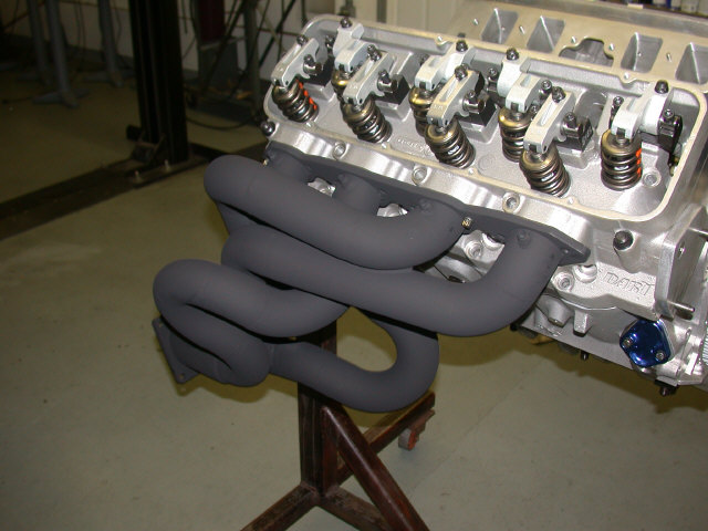
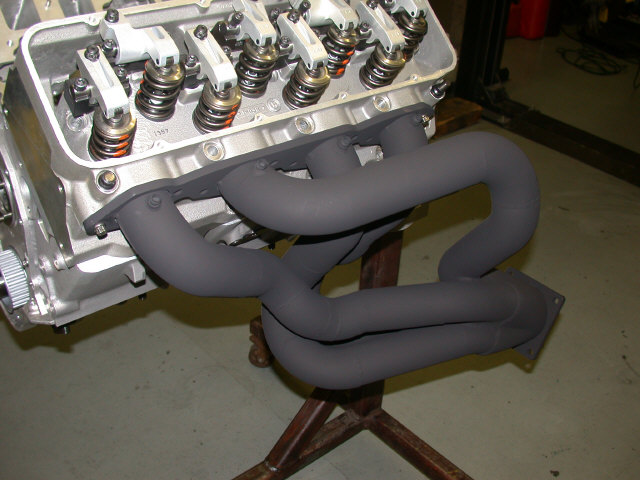
It took 8 weeks from start to finish but it was worth it. These headers were designed by a friend of mine - John Bzdel. I cut the pieces and TIG welded everything together. Johns part was much more difficult then mine.
They are 2-3/8" tubes with 4" collectors. The lengths are 28" +- 1/8". That's right, 1/8"! One of the reasons is took so long was John's obsession with getting the lengths as close as possible. He is a true perfectionist.
The material is mild steel tubing and I painted them with Plasti-Kote(sp?) header paint. I did not want to send these headers to get coated because with my luck they would get lost or something and the last thing I want to do is make another set.
Steve
[Modified by 542C2, 1:08 PM 11/17/2003]
Race Director


Joined: Jan 2000
Posts: 13,013
Likes: 2,253
From: Corsicana, Tx
2020 C2 of the Year - Modified Winner
2020 Corvette of the Year (performance mods)
C2 of Year Winner (performance mods) 2019
2017 C2 of Year Finalist
WOW!!!! :eek:
Those are fantastic looking. When do you think you can have mine done now that you have the bugs worked out? :D
Let's see...YOU're calling John a perfectionist? Jeez.....I doubt I could ever do anything to please him!! You're a little out there yourself you know!
Did you grind down all the welds or are they so pretty the black paint hides them? Either way, they sure look nice.
So I guess at this point, sticking together a Big Chief all aluminum 632", 1100 HP pump gas motor is chump work after building those dudes?
How's it coming BTW?
Congratulations.....I'm ready to go riding!
See ya,
JIM
PS- So much for all the big name shops that said it couldn't be done huh? What they meant to say was that THEY couldn't do it!
[Modified by 427Hotrod, 3:51 PM 11/17/2003]

Team Owner

Joined: May 2002
Posts: 29,017
Likes: 0
From: Clemson University SC
Cruise-In II Veteran
Cruise-In III Veteran
That's a very nice set of headers...there is no way in hell that engine will be limited by them. :cheers:
Thread Starter
Drifting
Joined: Jul 2002
Posts: 1,820
Likes: 283
From: Puyallup WA
Thanks, guys.
Jim: No welds were ground. They are just as they left my TIG welder. 1100 hp? I will be happy as heck with 1050 hp. 1100 hp would be nice but it may be out of reach. To all the shops that said it couldn't be done, here is the proof. Of course, I would have hated to have to pay one of those shops to try.
John: I will put it on the dyno as soon as I have it finished. The way that things go, this will probably be sometime in December or January.
TheWacoKid: I hope you are right. One thing is for sure, I will not be trying another set of headers on this motor while it is on the engine dyno.
As far as how things are going, I have finally got all the machine work done. This was a major nightmare. I am not at all happy with how long it all took but what can you do. I hope to order my pushrods tomorrow and that should be the last piece in the puzzle.
I coated the tops and skirts of my pistons and also the engine bearings. I was unhappy with how they turned out so I bought another set of bearings and I am sandblasting the coating off the skirts and applying a different brand.
Steve
Burning Brakes

Joined: Jul 1999
Posts: 922
Likes: 164
From: Hudson NH
WOW is right!!! This is an impressive piece of work. Whose collectors are you using? They appear short, although it may simply be an artifact from the picture angle. Are you going to run your existing exhaust system or do you plan to run even larger pipes?
Have you solved the hood height issue? I suspect you will run aggressive valve timing to exploit the flow of the Big Chief heads. How high do you plan to rev this engine?
Any guesstimates when you will run this engine in anger? Engine dyno or straight in your C2?
This is simply amazing. I am at a loss for words.
Take care,
Mark
Thread Starter
Drifting
Joined: Jul 2002
Posts: 1,820
Likes: 283
From: Puyallup WA
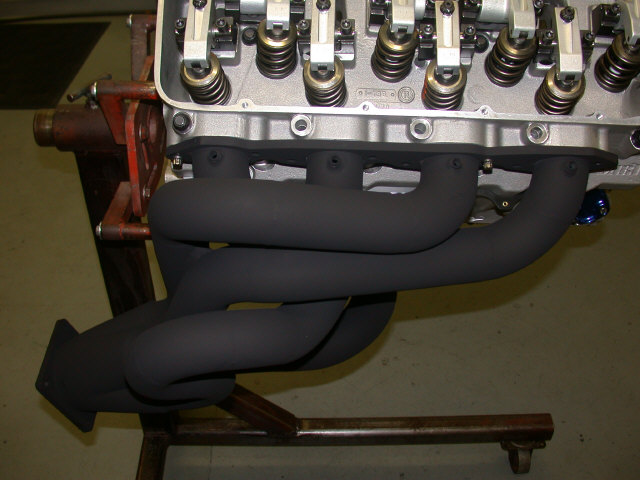
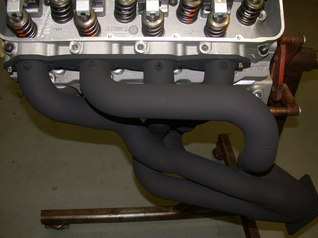
Thanks, Mark. All of the components came from Stahl. I spent about $900.00 for all the tubing, flanges, collectors, and shipping. By the way, I talked to Jere Stahl and he is one of the ones that said
The reason the collectors look short is because I cut them off. The flange that bolts to them will make the collectors 12" long when I run them open. My exhaust has been modified to connect up to the headers. The collector portion starts at 4" round then goes to 4" oval then finally to 3-1/2" oval. I will do testing to determine how much the capped up exhaust is costing me. If it is too high then I will fabricate a larger exhaust system. The good new is the increased ground clearance I have with this system.
Hood height has been successfully solved (with the help of Jim) and I do not need to fab another one(whew!). The cam for this motor is fricking enormous! I plan on posting a number of pictures of all the components as well as the assembly. There will be no "secrets" on this combination.
I want to keep the rpm under 7600. The piston speed will be more tolerable.
I will run the engine on an engine dyno first and then put it in the car - just like the last 2 times. I am hoping for a December or January time frame.
Steve
Corvette Stories
The Best of Corvette for Corvette Enthusiasts

Top 10 Corvette Engines RANKED by Peak Torque (70+ Years of Muscle!)
Joe Kucinski
Corvette ZR1X Will Be Pacing the Indy 500, And Could Probably Race, Too!
Verdad Gallardo
Top 10 Corvettes Coming to Mecum Indy 2026!
Brett Foote
Top 10 C9 Corvette MUST-HAVES to Fix These C8 Generation Flaws!
Michael S. Palmer
10 Revolutionary 'Corvette Firsts' Most People Don't Know
Joe Kucinski
5 Reasons to Upgrade to an LS6-Powered Corvette; 5 Reasons to Stay LT2
Michael S. Palmer
2027 Corvette vs The World: Every C8 vs Its Closest Competitor
Joe Kucinski
10 Most Common Corvette Problems of the Last 20 Years!
Joe Kucinski
5 MOST and 5 LEAST Popular Corvette Model Years in History!
Joe Kucinski
Safety Car


Joined: Dec 1999
Posts: 4,383
Likes: 1,183
From: Lexington,NC,USA
C1 of Year Finalist (track prepared) 2019
Steve:
Really sweet looking headers. I did a complete stainless steel exhaust system (from the manifolds back anyway) on a modified '62 so I can appreciate all the work that went into building them.
I am in the planning stage of another project that may involve building a custom set of headers, and I was wondering if you could tell me what you (or your friend John) used to "mock up" the primary tubes?
Charles
Thread Starter
Drifting
Joined: Jul 2002
Posts: 1,820
Likes: 283
From: Puyallup WA
Charles: The first thing John did was to get a couple of 24" lengths of flexible foil-type tubing in the correct diameter. He used this to get an idea of where the tubes would go.
I then cut up a bunch of J-tubes into 30*, 45*, 60*, 90*, and 120* sections - making sure to keep them on a perfect radius.. I also cut up some straight tubing (1 size smaller) into 3/4" long pieces. This was used to join the larger tubing together and keep everything properly aligned.
We used masking tape to hold everything together until all 4 tubes on each side were done. We then tacked all the pieces together. Next was TIG welding and finally the collector.
How is that for compressing 8 weeks into a few paragraphs?
Steve
Safety Car
Joined: Dec 1999
Posts: 4,383
Likes: 1,183
From: Lexington,NC,USA
C1 of Year Finalist (track prepared) 2019
Steve:
Thanks for the reply. A couple of other quick questions.
1. Do you know the brand name and/or source for the "flexible foil-type tubing" that was used?
2. What size tubing did you use for the primaries?
3. Regarding the small straight sections used to align the pieces - did you tack weld these into place on the inside or somehow secure them to one piece to prevent them from moving when you pushed the two outside pieces together? Were these pieces left inside the tubes after welding or did you somehow remove them after tack welding the joint?
Thanks,
Charles
Thread Starter
Drifting
Joined: Jul 2002
Posts: 1,820
Likes: 283
From: Puyallup WA
Charles:
1) The flexible foil-type tubing came from a local auto parts store. It is some kind of heat transfer hose between the exhaust manifold and the air cleaner.
2) The primaries are 2-3/8" diameter. I used the program from Headerdesign.com to come up with the diameter and length of the primaries and the collector size and length. They offer a great service.
3) The small straight sections were not tack welded into place. There is enough friction to hold them in place. Prior to removing ALL the masking tape, we used a magic marker to mark the position of the two pieces of tubing and then removed the small straight sections. We then lined up the marks and tack welded them.
I was actually quite concerned that we might have forgotten to remove some of the small straight sections so I bought a flexible articulating fiberscope from Powerhouse Products. This allowed me to look inside every tube to make sure that all the pieces were removed. I was also able to examine the inside quality of the welds.
Steve
[Modified by 542C2, 8:52 AM 11/24/2003]

Instructor

Joined: Mar 2002
Posts: 239
Likes: 0
From: Fredericksburg VA
Steve, that is one AWESOME job you did building those headers. I'm going to start turning a deaf ear to people who complain about fitting the proper size and length header into their engine compartments. You just made shorty headers obsolete.
As far as mocking up a set of custom headers, I usually suggest to people that they should cut appropriate lengths of flexible conduit. And, buy split foam pipe insulation to cover it at various points such that the approximate final pipe diameter is realized. This will make a near equal length header design by default. Then do this:
1. Cut the conduit to somewhat longer than the final primary length.
2. Stuff the foam covered conduit into the exhaust ports
3. Figure out the equal length geometry, use the split foam as needed
4. Block and clamp/strap the collectors into their final position
5. Cut and weld the flange plates to the first pipe pieces off the head
6. Install and mock it up again. You can slide the pipe pieces over the conduit.
7. Weld up the intermediate pipe pieces
8. Check out the alignment
9. Weld it up the rest of the way
You can easily aim the collectors at an x-pipe during this process if the header dimensions are long enough to clear the transmission. You can also aim the collectors at sidepipes, burying the proper collector length within the sidepipe body.
Thread Starter
Drifting
Joined: Jul 2002
Posts: 1,820
Likes: 283
From: Puyallup WA
Rodney, thanks for the compliments. I have to admit that I struggled with dimensions, theories, and design until I came across your website. I have recommended your site to a number of people.
It is very nice to have a source such as yours that has so much insight and information. I highly recommend anyone to take advantage of what you have to offer.
Steve
It is very nice to have a source such as yours that has so much insight and information. I highly recommend anyone to take advantage of what you have to offer.
Steve


Burning Brakes


Joined: Jul 2002
Posts: 1,126
Likes: 99
From: Nova Scotia
I want to keep the rpm under 7600. The piston speed will be more tolerable.
I will run the engine on an engine dyno first and then put it in the car - just like the last 2 times. I am hoping for a December or January time frame.
Steve
I will run the engine on an engine dyno first and then put it in the car - just like the last 2 times. I am hoping for a December or January time frame.
Steve