
New Way to do Electric Headlights
 08-16-2014, 04:28 PM
#1
Burning Brakes

Thread Starter

I have decided to convert the lights on my latest project (79 with a 454) to electric. I absolute despise the vacuum system and its Rube Goldberg approach to raising and lowering.
My son has a Pontiac WSR Firebird, and every couple of months he has to replace the drive gear in his pop up lights. So trying any of the GM approach has not appealed to me.
I'm going to try this my way, and not spend $1000.00.
First of all, I measured the distance I need to move the headlights, and found it to be about 2 1/2 inches. I scoured the web and stores looking for linear actuators that might fit the bill.
Found lots of them, but none that were about three inches. I found 2 and 4 were plentiful. The four inch actuators are too long to fit in the space behind the lights, and the 2 inch actuators don't have enough travel.
I was also concerned about stopping the actuator at the right time. Some of these have tremendous power. I didn't want the actuator to push the light assembly up out of the nose if something went wrong!!
And knowing me like I know me, if it can go wrong....well you know.
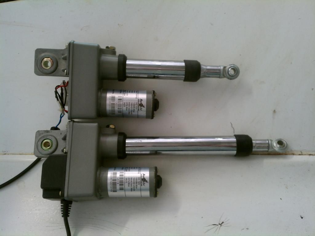
I decided on two actuators from Johnny Law Motors. They are 12 volt, Auto-Loc 4 inch travel, rated at pushing and pulling 150 lbs. $118.00 for both included shipping.
I also purchased the relay and switch system for an additional $50.00.
Well, I knew these were too long to fit in the space allotted, and 4 inches is too much travel, and 150 lbs would push the lights right out of the hood!!!
After talking to the folks at Johnny Law it was apparent I could make these actuators work. And one relay kit would work for two actuators.
Oh, if you go to the auto loc site, you will find the actuators but they are tremendously expensive there!
http://www.autoloc.com/catalog/Actua...near-Actuators
However, you can find these exact same actuators by auto-loc on Ebay at any number of places. I decided on Johnny Law motors because they apparently are also Auto Loc.
But this is the same actuator:
http://www.ebay.com/itm/Heavy-Duty-Linear-Actuator-150-lb-4-Inch-12-Volt-DC-PUSH-PULL-hot-street-rat-rod-/161387274810?pt=Motors_Car_Truck_Parts_Accessories&hash=item25936e623a&vxp=mtr
Now that I have the parts, it's time to go to work. The purpose of this installment of the project is to show how I went from 4 inch actuators to 3 inch actuators and made them so they fit in the allotted space.
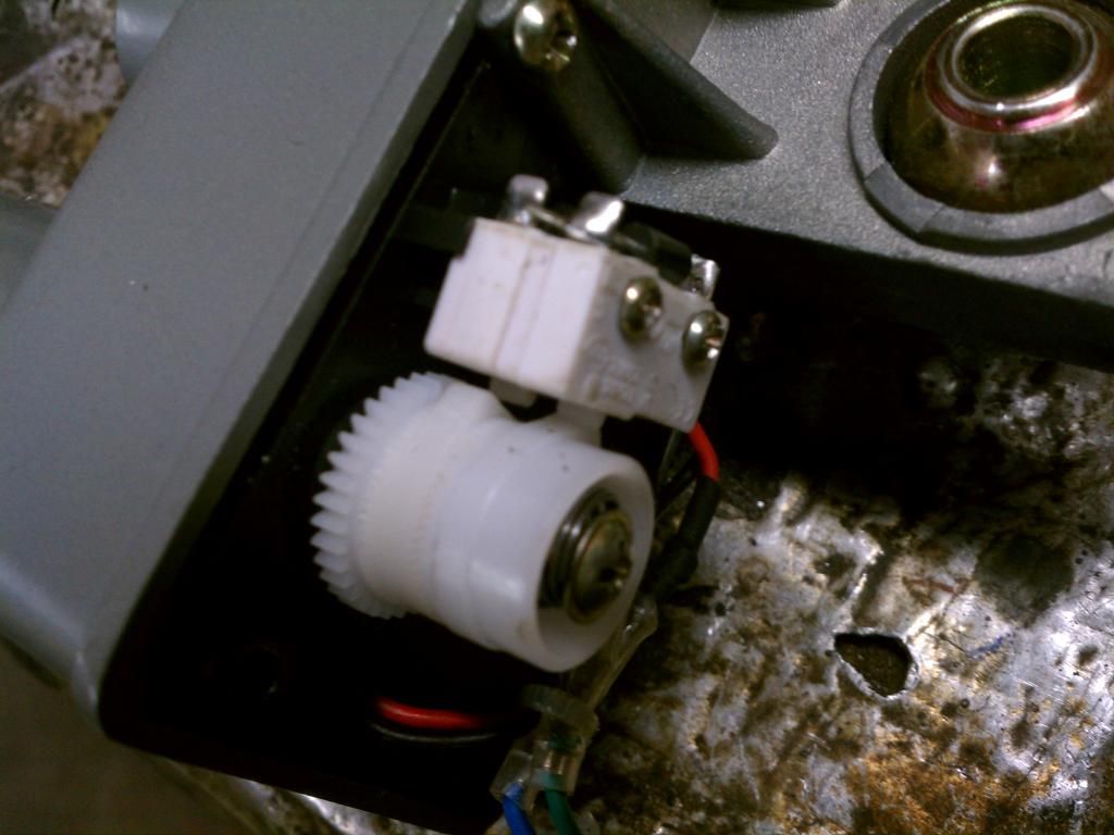
First of all, undo the bolt on top of the housing at the base of the chrome actuator. This will allow you to slide the assembly out of the housing. It is very simple. The chrome tube merely holds a threaded rod that slides into the gear housing and then up into the chrome tube. The actuator has a threaded sleeve that moves up or down as it rotates.
Amount of rotation is determines by two knots an wheels under the plastic cover. The limit of travel can be set anywhere you want. All you do is remove the spring loaded screw and adjust the geared plastic wheels to turn the motor on or off at a certain length.
This is all well and good, except the actuator is still too long to fit without hitting the radiator.
So it must be shortened
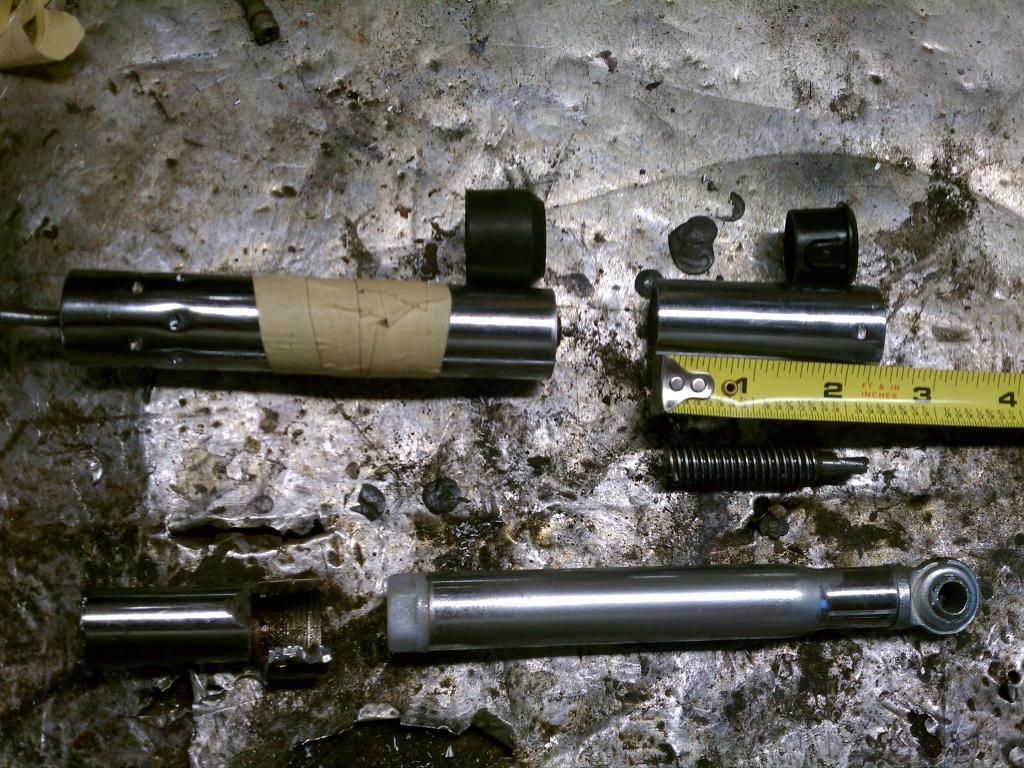
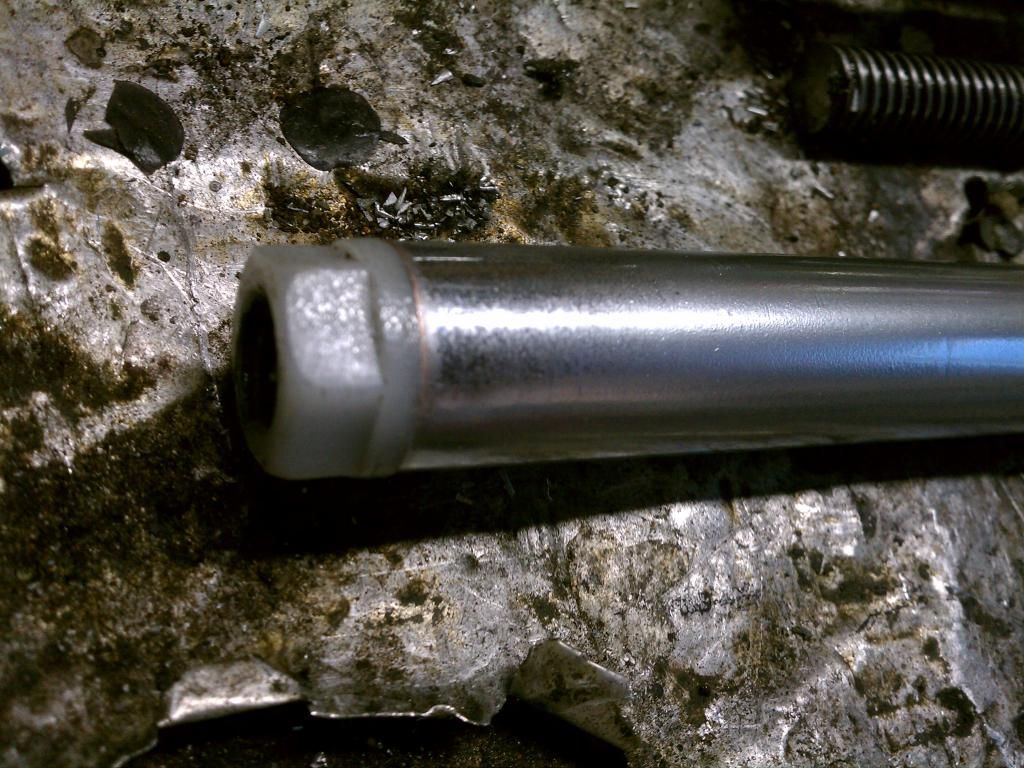
I carefully cut 2 3/8 inches off the drive screw housing. I did it with a cut off wheel on my grinder and was careful not to cut the drive screw on the inside. I wanted to cut the drive screw an 1/8 longer so I had room to properly trim and taper the end making it easy to thread into the sleeve. You can see the tip of the screw in the picture. Also the pieces I cut off. There is a plastic guide sleeve that is held in place on the end of the screw housing that is simply popped into place and secured in two holes. You can push those in and pope out the plastic sleeve. Drill holes in the cut end and replace the sleeve later.
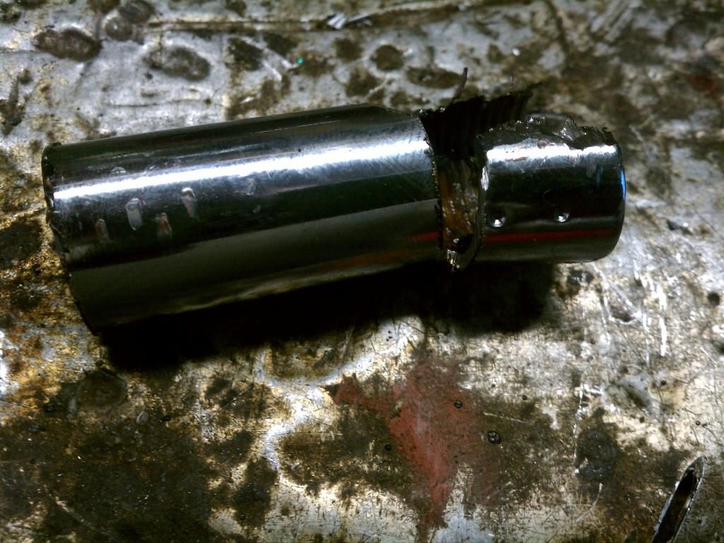
The actuator rod itself is a bit more of a challenge. The threaded insert is about an inch into the sleeve and is dimpled in place. DO NOT try to remove it with a wrench. You will ruin the insert. Simply measure up from the plastic insert 2 3/8 inches and cut the bottom off.
Then put the end in a vice, and CAREFULLY grind the metal away down to the nylon sleeve. NOT into the sleeve. Then you simply use vice grips to separate the end and get the threaded sleeve out.
There is also a small plastic washer that slides up into the actuator sleeve. Make sure you get that.
Now the hard part. You need a 5/8 by 18 tap for the end of actuator rod.
Simply tap the end, screw in the nylon insert (after pushing the nylon washer all the up into the top of the rod) and dimple the end with a punch to hold it in place.
I you don't have the tap and don't want to buy one, I suppose you could weld a nut in the end. That is what I was prepared to do, but I happen to have that tap in my tool kit.
Now I have the actuators ready and they will fit in the space allotted.
Next I am going to build the brackets for the actuator. This will involve cutting a slot in the housing as the actuator will angle downward to allow the hood to clear and the light cover to lock in the up position.
For that I am planning on using 1/8 inch sheet steel.
My son has a Pontiac WSR Firebird, and every couple of months he has to replace the drive gear in his pop up lights. So trying any of the GM approach has not appealed to me.
I'm going to try this my way, and not spend $1000.00.
First of all, I measured the distance I need to move the headlights, and found it to be about 2 1/2 inches. I scoured the web and stores looking for linear actuators that might fit the bill.
Found lots of them, but none that were about three inches. I found 2 and 4 were plentiful. The four inch actuators are too long to fit in the space behind the lights, and the 2 inch actuators don't have enough travel.
I was also concerned about stopping the actuator at the right time. Some of these have tremendous power. I didn't want the actuator to push the light assembly up out of the nose if something went wrong!!
And knowing me like I know me, if it can go wrong....well you know.
I decided on two actuators from Johnny Law Motors. They are 12 volt, Auto-Loc 4 inch travel, rated at pushing and pulling 150 lbs. $118.00 for both included shipping.
I also purchased the relay and switch system for an additional $50.00.
Well, I knew these were too long to fit in the space allotted, and 4 inches is too much travel, and 150 lbs would push the lights right out of the hood!!!
After talking to the folks at Johnny Law it was apparent I could make these actuators work. And one relay kit would work for two actuators.
Oh, if you go to the auto loc site, you will find the actuators but they are tremendously expensive there!
http://www.autoloc.com/catalog/Actua...near-Actuators
However, you can find these exact same actuators by auto-loc on Ebay at any number of places. I decided on Johnny Law motors because they apparently are also Auto Loc.
But this is the same actuator:
http://www.ebay.com/itm/Heavy-Duty-Linear-Actuator-150-lb-4-Inch-12-Volt-DC-PUSH-PULL-hot-street-rat-rod-/161387274810?pt=Motors_Car_Truck_Parts_Accessories&hash=item25936e623a&vxp=mtr
Now that I have the parts, it's time to go to work. The purpose of this installment of the project is to show how I went from 4 inch actuators to 3 inch actuators and made them so they fit in the allotted space.

First of all, undo the bolt on top of the housing at the base of the chrome actuator. This will allow you to slide the assembly out of the housing. It is very simple. The chrome tube merely holds a threaded rod that slides into the gear housing and then up into the chrome tube. The actuator has a threaded sleeve that moves up or down as it rotates.
Amount of rotation is determines by two knots an wheels under the plastic cover. The limit of travel can be set anywhere you want. All you do is remove the spring loaded screw and adjust the geared plastic wheels to turn the motor on or off at a certain length.

This is all well and good, except the actuator is still too long to fit without hitting the radiator.
So it must be shortened

I carefully cut 2 3/8 inches off the drive screw housing. I did it with a cut off wheel on my grinder and was careful not to cut the drive screw on the inside. I wanted to cut the drive screw an 1/8 longer so I had room to properly trim and taper the end making it easy to thread into the sleeve. You can see the tip of the screw in the picture. Also the pieces I cut off. There is a plastic guide sleeve that is held in place on the end of the screw housing that is simply popped into place and secured in two holes. You can push those in and pope out the plastic sleeve. Drill holes in the cut end and replace the sleeve later.
The actuator rod itself is a bit more of a challenge. The threaded insert is about an inch into the sleeve and is dimpled in place. DO NOT try to remove it with a wrench. You will ruin the insert. Simply measure up from the plastic insert 2 3/8 inches and cut the bottom off.
Then put the end in a vice, and CAREFULLY grind the metal away down to the nylon sleeve. NOT into the sleeve. Then you simply use vice grips to separate the end and get the threaded sleeve out.

There is also a small plastic washer that slides up into the actuator sleeve. Make sure you get that.
Now the hard part. You need a 5/8 by 18 tap for the end of actuator rod.

Simply tap the end, screw in the nylon insert (after pushing the nylon washer all the up into the top of the rod) and dimple the end with a punch to hold it in place.
I you don't have the tap and don't want to buy one, I suppose you could weld a nut in the end. That is what I was prepared to do, but I happen to have that tap in my tool kit.
Now I have the actuators ready and they will fit in the space allotted.
Next I am going to build the brackets for the actuator. This will involve cutting a slot in the housing as the actuator will angle downward to allow the hood to clear and the light cover to lock in the up position.
For that I am planning on using 1/8 inch sheet steel.


Last edited by commander_47; 08-17-2014 at 05:58 PM. Reason: Adding update 1
 08-16-2014, 04:38 PM
#2
Team Owner


I lost my entire headlight assy's to a damn Florida deer one night back in '98, the then easy evailable Eckler's sugar scoops ordered next day, and there was no salvage to the OEM stuff, as year went by, I decided to use lo profile later Camaro bulbs, and so junkyarded the entire setup, reduced the openings in the body by some 50% fore/aft and mounted the lights with camaro mounting hardware.....
I have always felt the old geeky looking headlights looked stupid on the car, when the doors were open, but it was what they had back when, I would sell off the operating mechanisms for about 1500 bux, and pocket the money for a couple trays, and some junkyard parts, and call it a day,....except for body work.....
 see my shutterfly account below for a few pix....
I have always felt the old geeky looking headlights looked stupid on the car, when the doors were open, but it was what they had back when, I would sell off the operating mechanisms for about 1500 bux, and pocket the money for a couple trays, and some junkyard parts, and call it a day,....except for body work.....
see my shutterfly account below for a few pix....
08-16-2014, 04:53 PM
#3


You could have simply used an external limit switch and diode, easy to adjust the stroke that way. I did my wiper door with a linear actuator a few years ago.
Probably do the headlights the same way if they go bad.
Probably do the headlights the same way if they go bad.
 08-17-2014, 06:15 PM
#4
Burning Brakes
Thread Starter
I opted not to use it for several reasons:
1. It would cost an additional $75.00
2. Since the actuators had to be shortened anyway, I could set how far the actuators actually could go.
3. I am comfortable with the mechanical switch shutoff.
Today I started on the brackets. I will tell you that there is no way these will fit if you have an air conditioner condenser, or electric fans on the outside of the radiator.
There simply isn't enough room.
I measured pretty carefully to make sure I could clear the radiator and that the hood could open.
I wanted at least 1/2 inch from radiator, and I need a minimum of 6 inches to clear the hood.
By shortening the actuator, I just barely make that goal. In fact, I'm at exactly 6 inches for the arc of the hood. I may have to relieve some from the sides of the brackets.
We'll see in the next few days when I put the hood back on for testing.
I clear the radiator pretty good. May be rounding off the end of the back bracket, especially on the outside as that pointy bottom looks scary pointing at the radiator.

I had to cut the bottom of the O out of the headlight bracket itself. The rod for the actuator passes through this area. I'm thinking of welding a simple reinforcing piece of steel connecting the bottom of the brackets just for piece of mind. They are pretty robust, especially with the two rods on the inside connected to the bottom two bolts.

I may need to cut arches out of the top of the brackets to allow the hood to open. I measured that I would need 6 inches, and I'm exactly at six now. I would feel better if I had 1/2 inch or so clearance. We'll know for sure in the next day or two. I have aluminum and nylon spacers to fit into the actuator mounting points, and I plan to use two of the return springs, not four.
I have a test video to post in a day or two.
 08-17-2014, 06:37 PM
#5
Race Director


commander47,
I can TRULY appreciate your dedication to doing this. God knows I have to implement systems in Corvettes that they did not come with.
I hope your tests go well.
I have had several Corvettes come in my shop with some type of electric conversion and I can say that on all of them I am not impressed. The headlight hit so hard and BANG when being raised and lowered.....so I would offer this....hopefully you can control the 150 pounds of force when they are being opened and closed. That amount of force is much higher than what is needed. BECAUSE on the Corvettes that have come into my shop like I wrote...the front end around the headlights would shutter when the headlights were raised and lowered...and I feel that it was worse than if they repaired the vacuum system.
Looks very CLEAN so far. And my only concern is if this system you are designing was installed in a Corvette with an A/C condenser.
DUB
08-18-2014, 06:34 AM
#6
Racer

Member Since: Jul 2008
Location: Gippsland, VIC Australia
Posts: 258
Likes: 0
Received 1 Like
on
1 Post
I'm interested.
It shouldnt be to hard to fine tune the speed & ram power with a dimmer switch.
I've got AC, so to get around the clearance issue, I'd probably set it up as a pull system to a common shaft between both sides with an acuator rod to each light...
It shouldnt be to hard to fine tune the speed & ram power with a dimmer switch.
I've got AC, so to get around the clearance issue, I'd probably set it up as a pull system to a common shaft between both sides with an acuator rod to each light...
08-18-2014, 12:05 PM
#7
Burning Brakes
Thread Starter
I was thinking of trying to do a pull system with only one actuator. Seems to me that with all the vacuum stuff out of the nose, an actuator could be located there facing toward the rear.
Then you would need linkage connecting the two lights in the center.
What I could not overcome with a design was the V shape from the lights. In other words, a straight shaft connected to one light, and then the other, will meet in the middle at roughly the same angle as the shark nose itself. Geometry won't let one actuator work unless the rods are straight across.
To me, a one actuator system is the ideal
 .
.I made a slight miscalculation with my clearance.
When I measured for the hood, the hood was up but I did not allow for the extra travel needed to lock in the support. So after pondering and considering several options, I decided to shorten the hood support.
This is surprisingly easy to do. I cut an inch off the bottom of the long end.

Then I drilled a new hole and and put in a new rivet.

It really doesn't look any different when it's locked into place:

But I have lots of clearance now and no issues with the radiator or the hood.
Next up is to take it all apart and work on the settings, and trimming the brackets.
 08-18-2014, 01:18 PM
#8
Melting Slicks

Seems that you could use a z-bar type arrangement, put the actuator low and parallel to the condenser, and leave the actuator length alone.That would give plenty of room for the A/C.
08-18-2014, 06:14 PM
#9
Burning Brakes
Thread Starter
commander47,
The headlight hit so hard and BANG when being raised and lowered.....so I would offer this....hopefully you can control the 150 pounds of force when they are being opened and closed. That amount of force is much higher than what is needed. BECAUSE on the Corvettes that have come into my shop like I wrote...the front end around the headlights would shutter when the headlights were raised and lowered...and I feel that it was worse than if they repaired the vacuum system.
DUB
The slot allows the ram to change angle and push it that last inch into lock. The springs maintain tension on the housing and lever so it doesn't "pop" into place.
Same when they come down. There is an inch of travel before they unlock. If the springs don't take up the slack, the light housing will literally fall an inch. That causes the clunk and shudder.
I have solved all my clearance problems now , and I've had it on the bench setting the limits of travel and making sure all is well.
I'm not sure if I posted the video right. Maybe you can see it operate in this video.
The only concern I have now is how loud the motor is. It kind of whines and seems like there's a dying cat under the hood. Might have to insulate this somehow.
http://vid1340.photobucket.com/album...ps6cfe2e71.mp4
08-18-2014, 07:03 PM
#10
Race Director
DUB
08-28-2014, 01:25 PM
#11
Burning Brakes
Thread Starter
Here is the latest update on this project. I was delayed just a little while I got the 454 ready for the machine shop. I have the aluminum rectangular port heads for it, and it's at the shop now getting its pistons fitted.
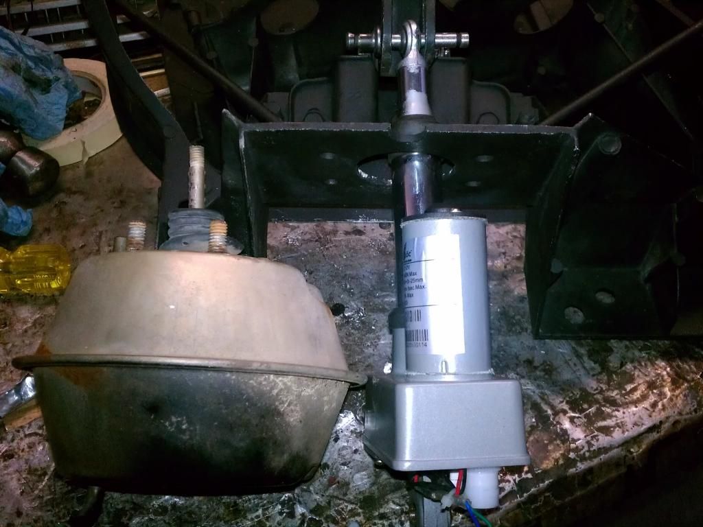
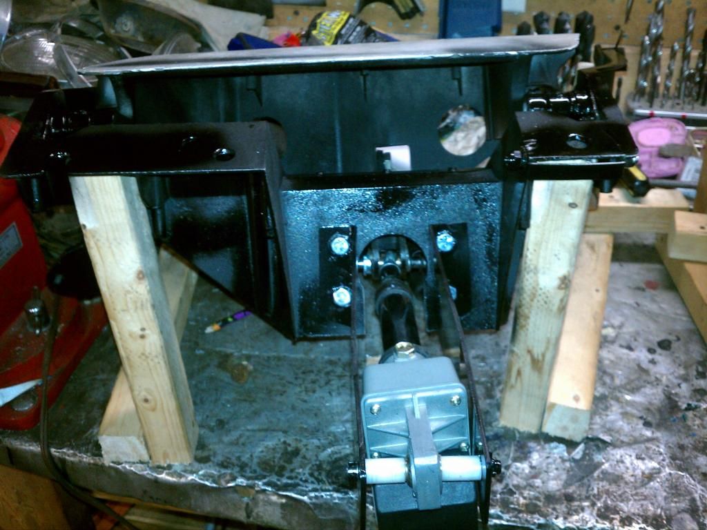
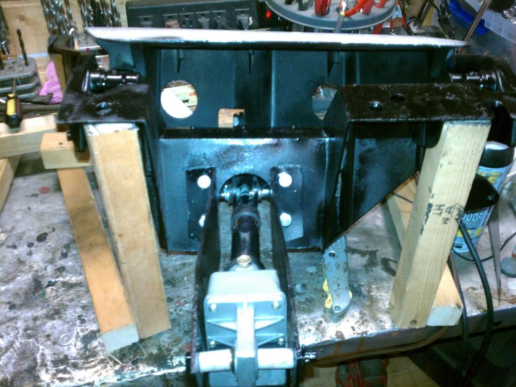
On the lights, I completed the right side and mounted both lights on the bench side by side for testing. I am very happy with the performance. And best of all, total cost for everything including the steel for the brackets, hardware, relay kit, motors et al was just shy of $200.00.
They both move up and down together and lock in place perfectly. By cutting the screw I don't have to worry about the length they travel.
Also, the motor shuts off at a set distance. So I am comfortable without buying extra limiters.
I have run them up and down about 25-30 times together now without a hitch. You can see them on the bench in this video.
http://vid1340.photobucket.com/album...psceb9c691.mp4
I did all the little things and wanted to let you all know the extras.
1. Use all the springs. The springs take up all the slack and govern the angle of the lights. These lock in the up position and have to be unlocked to come down. The springs assure this happens.
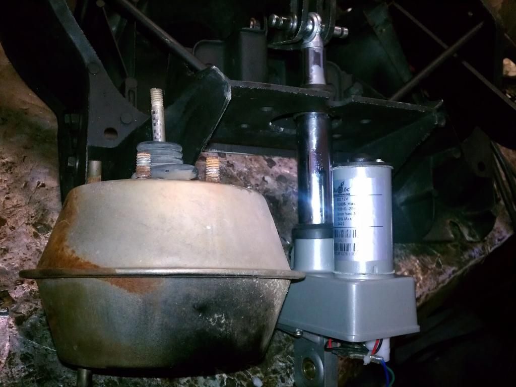
2. I turned down the small rear pin to fit the hole in the push rod clevis. I then turned a nylon busing with a collar to fill in the space. You can see it on the left in this picture.
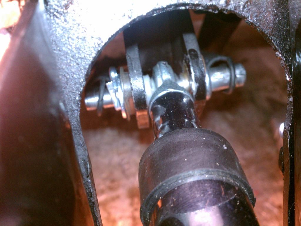
I also made some nylon bushings to center the motors at the rear and to keep the motor from touching the brackets. The motors twist a little bit and the brackets stop them from going too far. But looseness is the key!!! Not too tight.
Both motors will work off of one relay system. I plan to put the rocker switch on the console where the mirror select switch would go for electric mirrors. I'm going to just put a little round Corvette symbol where toggle switch goes. Haven't decided if I should wire these to a key switch or not. Since the lights can be turned on with the key off, I will probably make the motors run the same way. I just don't want my grand kids playing with the switch!!!!!!!
I will be putting these into the car in the next couple of weeks and will post how they look in the car. Now remember, this car is a work in progress, so forget everything else,
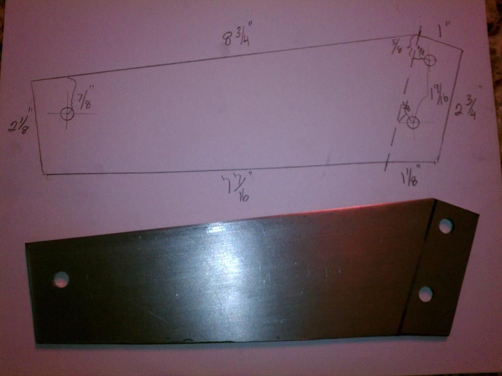
Anyone wanting to look into doing this might find the template helpful.
On the lights, I completed the right side and mounted both lights on the bench side by side for testing. I am very happy with the performance. And best of all, total cost for everything including the steel for the brackets, hardware, relay kit, motors et al was just shy of $200.00.
They both move up and down together and lock in place perfectly. By cutting the screw I don't have to worry about the length they travel.
Also, the motor shuts off at a set distance. So I am comfortable without buying extra limiters.
I have run them up and down about 25-30 times together now without a hitch. You can see them on the bench in this video.
http://vid1340.photobucket.com/album...psceb9c691.mp4
I did all the little things and wanted to let you all know the extras.
1. Use all the springs. The springs take up all the slack and govern the angle of the lights. These lock in the up position and have to be unlocked to come down. The springs assure this happens.
2. I turned down the small rear pin to fit the hole in the push rod clevis. I then turned a nylon busing with a collar to fill in the space. You can see it on the left in this picture.

I also made some nylon bushings to center the motors at the rear and to keep the motor from touching the brackets. The motors twist a little bit and the brackets stop them from going too far. But looseness is the key!!! Not too tight.


Both motors will work off of one relay system. I plan to put the rocker switch on the console where the mirror select switch would go for electric mirrors. I'm going to just put a little round Corvette symbol where toggle switch goes. Haven't decided if I should wire these to a key switch or not. Since the lights can be turned on with the key off, I will probably make the motors run the same way. I just don't want my grand kids playing with the switch!!!!!!!
I will be putting these into the car in the next couple of weeks and will post how they look in the car. Now remember, this car is a work in progress, so forget everything else,
Anyone wanting to look into doing this might find the template helpful.

Last edited by commander_47; 08-28-2014 at 01:27 PM.
08-29-2014, 06:44 PM
#12
Le Mans Master

i applaud your ingenuity and craftsmanship, once i learned to work on the vacuum system it is actually simple.

 08-29-2014, 08:58 PM
#14
Burning Brakes
Thread Starter

I do know that I didn't want to spend hundreds and hundreds of dollars. I also wanted something easy to maintain.
My motors are held in place with two pins. I can replace the entire motor in about 5 minutes if I ever have to. Of course, I will need to have a motor pre shortened to do that.
Also, these motors are cheap. 56.00 each and I don't have to hunt them down in a junkyard. The little wheels in the trans am and Camaro are $25.00 plus!!!!
If I was to do this again, I believe I would do a single motor system. I believe it would be very easy. A simple Z bar arrangement connecting the two lights, and one motor in the nose pointing to the rear.
Quite honestly, I can't stand the vacuum system. It is overly complicated and totally clutters up the engine compartment with a lot of hoses and doo dads.
I don't know if this system is better than some others or not. I guess you just have to decide for yourself.
I am merely offering another alternative.
08-29-2014, 09:45 PM
#15
Le Mans Master
There was a gent at Carlisle this year that was demo'ing a system that used Miata headlight motors and could be used with the original headlight switch or changed out with a C4 Corvette headlight switch (depending on whether you wanted to go behind the dash or not). It appeared to be a very smooth and efficient system and pretty well engineered. He was selling the complete system for $495. (If anyone would like his contact information, just PM me.)
By the way, I do admire anyone willing to spend the time and energy to try and improve some of the old systems on these cars. I'm all for anything that makes owning one of these gems less painful and expensive. Thanks Commander for your efforts, without which many of these old "relics" would have been retired long ago... and that would be a tragedy.
Good luck... GUSTO
08-29-2014, 11:59 PM
#16
I don't know anything about the Miata/Probe switch.
I do know that I didn't want to spend hundreds and hundreds of dollars. I also wanted something easy to maintain.
My motors are held in place with two pins. I can replace the entire motor in about 5 minutes if I ever have to. Of course, I will need to have a motor pre shortened to do that.
Also, these motors are cheap. 56.00 each and I don't have to hunt them down in a junkyard. The little wheels in the trans am and Camaro are $25.00 plus!!!!
If I was to do this again, I believe I would do a single motor system. I believe it would be very easy. A simple Z bar arrangement connecting the two lights, and one motor in the nose pointing to the rear.
Quite honestly, I can't stand the vacuum system. It is overly complicated and totally clutters up the engine compartment with a lot of hoses and doo dads.
I don't know if this system is better than some others or not. I guess you just have to decide for yourself.
I am merely offering another alternative.
https://www.corvetteforum.com/forums...c-new-way.html
That is a swap that uses Miata or Probe motors. They can be had for 25 bucks a pop from http://www.planet-miata.com/ no junk yard searching needed.
Keep up the good work on the actuator setup, I personally like it a lot!
08-30-2014, 08:42 AM
#17
Burning Brakes
Thread Starter
When you get bored and want to read a long long thread:
https://www.corvetteforum.com/forums...c-new-way.html
That is a swap that uses Miata or Probe motors. They can be had for 25 bucks a pop from http://www.planet-miata.com/ no junk yard searching needed.
Keep up the good work on the actuator setup, I personally like it a lot!
https://www.corvetteforum.com/forums...c-new-way.html
That is a swap that uses Miata or Probe motors. They can be had for 25 bucks a pop from http://www.planet-miata.com/ no junk yard searching needed.
Keep up the good work on the actuator setup, I personally like it a lot!

I like how they operate with the switch. Definitely a clean set up.
There was an issue with the wheel cracking in one of the posts. That is something I was trying to avoid.
Also, seems like that system solves the clearance problem.
I like the way mine come up. Kind of dramatic.
I do believe I'll put some sort of insulation around them to quiet them down a bit. Not sure that will matter if the engine is running.