
Gen/Fuel Light with Autometer Gauges
 09-20-2016, 10:30 PM
#1
Instructor

Thread Starter
I've been going through all the threads I can find regarding aftermarket Autometer gauges for my 1980 corvette. Everything I finding just shows everyone wiring up the gauges, but there is no mention of keeping the Low Fuel or Generator lights. Does everyone just discard the low fuel/gen lights? If not, how do you install them without the original metal housing that the stock gauges were in?
Second, I thought we needed the gen light to be functional for the alternator/charging system to work correctly. Is this not the case?
Any help would be appreciated. Pictures would be great. Thanks
Second, I thought we needed the gen light to be functional for the alternator/charging system to work correctly. Is this not the case?
Any help would be appreciated. Pictures would be great. Thanks
 09-21-2016, 04:35 AM
#2
Melting Slicks


 09-21-2016, 08:53 PM
#3
Instructor
Thread Starter
Just checking back. Still trying to figure out if I can wire the gauges without the fuel/gen light, or if they are required? Anyone.....Bueller.....
09-27-2016, 02:57 AM
#4

Hope this helps.
10-01-2016, 12:31 PM
#5
Instructor
Thread Starter
Thanks for the reply. I'm trying to visualize what you did. Did you keep using the original printed circuit board then, or only the metal plate?
10-03-2016, 12:02 PM
#6
Race Director

Member Since: Apr 2007
Location: South Western Ontario
Posts: 11,061
Received 845 Likes
on
721 Posts

You need the generator light or a resistor to make it charge. You can just use a 75 ohm, 5 watt resistor to replace the light.
You could just eliminate the low fuel light.
You could just eliminate the low fuel light.
10-12-2016, 07:57 PM
#7
BBB
I did not use the stock circuit board. I took a schematic and figured out what wires in the stock harness went where and then just soldered into the harness and made my own harness for the idiot lights and the gauges. To make room for the gauges you cannot use the circuit board.
This is not the best shot of the gauges but here it is.
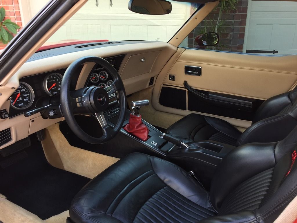
I used the angle rings to angle the center stack toward the driver. The gauges are not recessed at all.
This is not the best shot of the gauges but here it is.

I used the angle rings to angle the center stack toward the driver. The gauges are not recessed at all.
10-13-2016, 05:43 PM
#8
Racer
Member Since: Apr 2015
Location: Carrollton, Georgia
Posts: 412
Likes: 0
Received 12 Likes
on
7 Posts
BBB
I did not use the stock circuit board. I took a schematic and figured out what wires in the stock harness went where and then just soldered into the harness and made my own harness for the idiot lights and the gauges. To make room for the gauges you cannot use the circuit board.
This is not the best shot of the gauges but here it is.
I used the angle rings to angle the center stack toward the driver. The gauges are not recessed at all.
10-13-2016, 06:13 PM
#9
Yes. So does the seat belt and in my case the check engine light.
10-15-2016, 07:21 PM
#10
Instructor
Thread Starter
BBB
I did not use the stock circuit board. I took a schematic and figured out what wires in the stock harness went where and then just soldered into the harness and made my own harness for the idiot lights and the gauges. To make room for the gauges you cannot use the circuit board.
This is not the best shot of the gauges but here it is.
I used the angle rings to angle the center stack toward the driver. The gauges are not recessed at all.
I did not use the stock circuit board. I took a schematic and figured out what wires in the stock harness went where and then just soldered into the harness and made my own harness for the idiot lights and the gauges. To make room for the gauges you cannot use the circuit board.
This is not the best shot of the gauges but here it is.
I used the angle rings to angle the center stack toward the driver. The gauges are not recessed at all.
Wouldn't it be easier to just use the plastic line splicers that just snap onto the original wire? Why go the soldering route?
10-16-2016, 11:04 AM
#11
Melting Slicks
Thanks for the info, your car looks great. I've been noticing a lot of people when they're talking about wiring up the gauges, many say they soldered into the original harness. I'm guessing you didn't cut the original plug off. Did you just strip some insulation off of each wire, wrap the new wire into it, and then solder them together?
Wouldn't it be easier to just use the plastic line splicers that just snap onto the original wire? Why go the soldering route?
Wouldn't it be easier to just use the plastic line splicers that just snap onto the original wire? Why go the soldering route?
I know your dash doesn't have to be waterproof, but even the moisture in the air can eventually corrode wire. You can solder if you want, but even solder can corrode and should be protected from the environment, and obviously insulated at a minimum. I know go a little overboard, but it's because I build wire harnesses for a living.
 10-18-2016, 06:17 PM
#12
Thanks for the info, your car looks great. I've been noticing a lot of people when they're talking about wiring up the gauges, many say they soldered into the original harness. I'm guessing you didn't cut the original plug off. Did you just strip some insulation off of each wire, wrap the new wire into it, and then solder them together?
Wouldn't it be easier to just use the plastic line splicers that just snap onto the original wire? Why go the soldering route?
Wouldn't it be easier to just use the plastic line splicers that just snap onto the original wire? Why go the soldering route?