




Points Install Question

Thread Starter
Cruising

Joined: Oct 2006
Posts: 13
Likes: 0
From: Annapolis MD
 Points Install Question
My 67 327 has developed a bad miss and is not burning all the fuel under load. I have changed everything electrical possible, plugs, wires, cap, rotor, coil, etc. No change. The only component I have not changed is the electronic points replacement unit (Pertronix) the previous owner installed. To eliminate this as a possible cause, I want to install a set of points.
My question, do I just run a single wire from the points to the positive side of the coil? Appreciate any help.
My question, do I just run a single wire from the points to the positive side of the coil? Appreciate any help.

Tech Contributor


Joined: Aug 1999
Posts: 14,384
Likes: 6,412
From: At my Bar drinking and wrenching in Lafayette Colorado
Wire goes from the points to the negative side of the coil. Make sure you still have the ballast resistor installed in the positive feed circuit.

Team Owner


Joined: Oct 2000
Posts: 38,897
Likes: 1,927
From: Washington Michigan
You might also check where the red power feed wire from the existing Pertronix unit is connected; it needs a full 12 volts to operate properly (especially at high rpm), and if it's connected to the coil (+) terminal, it's only getting 7-8 volts (assuming your ballast resistor is still installed). 
Thread Starter
Cruising
Joined: Oct 2006
Posts: 13
Likes: 0
From: Annapolis MD
Thank you for the quick reply and proper wiring for the points. The Pertronix unit was wired directly to the negative and positive terminals on the coil and I do have the original ballast resistor in place. Not sure how it was running well prior to this problem. When testing the voltage on the positive side of the coil I read 4.81 VDC with the key in the on position and 10.30 VDC when cranking the engine. Thanks again for the support.

Burning Brakes

Joined: May 2003
Posts: 990
Likes: 4
From: DAVIE/FORT LAUDERDALE FL
Originally Posted by JohnZ
You might also check where the red power feed wire from the existing Pertronix unit is connected; it needs a full 12 volts to operate properly (especially at high rpm), and if it's connected to the coil (+) terminal, it's only getting 7-8 volts (assuming your ballast resistor is still installed).
Ken
Last edited by kenEDMUNDS; Oct 11, 2006 at 03:56 PM.

Safety Car


Joined: Feb 2006
Posts: 4,142
Likes: 705
Originally Posted by kenEDMUNDS
John, if you used a Pertronix, how would you wire it? I have installed a couple of them using the ballast resistor am not sure I am getting full performance. Also, I would not think a Pertronix would cause a miss-more like a run/no run situation?
Ken
Ken
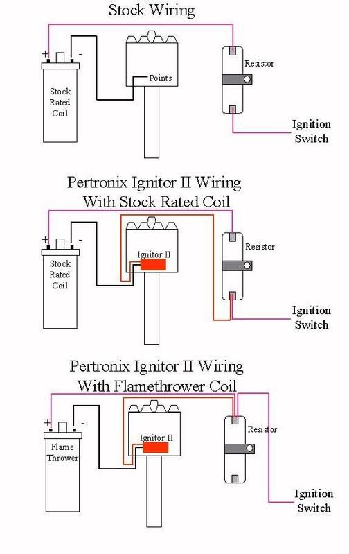
I stole this diagram from JohnZ...............who apparently stole it from someone else on the forum..................hmmm....his name has escaped me for the moment.
Disclaimer: Apparently, even the people at Pertronix are not sure how to wire them so use this diagram with discretion.
Corvette Stories
The Best of Corvette for Corvette Enthusiasts

Corvette & Porsche 911: How Two Icons Conquered the Last 25 Years
Joe Kucinski
2027 Chevrolet Silverado 1500 First Look: Everything You NEED to Know!
Michael S. Palmer
5 Best & 5 Worst Corvette Daily Drivers
Joe Kucinski
The Headlights of Every Corvette Generation Explained
Joe Kucinski
5 Best & 5 Most Overrated Corvette Track Packages of All Time!
Joe Kucinski
Every 2027 Corvette Engine Explained
Joe Kucinski
Designer Imagines A Corvette That Looks More Like a Corvette Than the Corvette
Verdad Gallardo
10 Ugly Corvettes That We Still Kinda Love
Joe Kucinski
Top 10 Most Expensive Corvettes Ever Sold on Bring A Trailer
Brett Foote
Tech Contributor


Joined: May 2005
Posts: 15,576
Likes: 118
From: Conroe Texas
Originally Posted by buns
I stole this diagram from JohnZ...............who apparently stole it from someone else on the forum..................hmmm....his name has escaped me for the moment.
Disclaimer: Apparently, even the people at Pertronix are not sure how to wire them so use this diagram with discretion.
Disclaimer: Apparently, even the people at Pertronix are not sure how to wire them so use this diagram with discretion.

That diagram is probably the only thing I've done on the forum lately that doesn't sound like whining and complaining
Tech Contributor
Joined: May 2005
Posts: 15,576
Likes: 118
From: Conroe Texas
Originally Posted by piper
I have some information on this How do i attact something into my post I have scanned something i want to post thank You Ed
http://forums.corvetteforum.com/show...t=post+picture
Burning Brakes

Joined: Oct 1999
Posts: 1,016
Likes: 1
From: Maine
I can not get it to work sh-- I have the direction on the Flame Thrower and the Pertronix and it said to leave the ballast resister along Just hook the red wire from the Ignitor to the ignition switch side of the resister and you still have the positive side of the coil wire going to the resister Maybe that is the way the picture shows it but I do not see the other wire I have two good pictures of it but I can not get them on
PS This is the 1.5 ohm Flame Thrower
PS This is the 1.5 ohm Flame Thrower
Last edited by piper; Oct 12, 2006 at 12:09 AM.
Tech Contributor
Joined: May 2005
Posts: 15,576
Likes: 118
From: Conroe Texas
I have the direction on the Flame Thrower and the Pertronix and it said to leave the ballast resister along Just hook the red wire from the Ignitor to the ignition switch side of the resister and you still have the positive side of the coil wire going to the resister Maybe that is the way the picture shows it but I do not see the other wire I have two good pictures of it but I can not get them on
The red wire from the Pertronix goes to the ignition switch side of the ballast resistor.
The black wire from the Petronix goes to the negative side of the coil.
The coil side of the ballast resistor (the wire that goes to the + side of teh coil) should be moved to the other side of the resistor, where the pertronix red wire, and the ignition wire, are located.
The end result is you'll have 3 wires on the same terminal on the resistor, no wires on the other terminal on the resistor.
Burning Brakes
Joined: Oct 1999
Posts: 1,016
Likes: 1
From: Maine
The direction for the Pertronix and the flame throws said,Do not take the ballast resister out of the mix. I have three things scanned now and I do not know how to post them but I can send them to anybody that want them and it shows that you do not wire it the way you say Mine is wired the way the direction are and was done 2 years ago and it is find Maybe lars can jump in
Last edited by piper; Oct 12, 2006 at 08:37 AM.
Tech Contributor
Joined: May 2005
Posts: 15,576
Likes: 118
From: Conroe Texas
Originally Posted by piper
The direction for the Pertronix and the flame throws said,Do not take the ballast resister out of the mix. I have three things scanned now and I do not know how to post them but I can send them to anybody that want them and it shows that you do not wire it the way you say Mine is wired the way the direction are and was done 2 years ago and it is find Maybe lars can jump in

Thread Starter
Cruising
Joined: Oct 2006
Posts: 13
Likes: 0
From: Annapolis MD
Thanks to all for the input and diagram. Installing the points did not correct the problem, so I will move on to timing and the fuel system. Quick question, I am still trying to determine if I have a ballast resistor. Where would it be located on a 67? I want to ensure I re-install the Pertronix correctly.
Tech Contributor
Joined: Aug 1999
Posts: 14,384
Likes: 6,412
From: At my Bar drinking and wrenching in Lafayette Colorado
Should be right on the firewall, near the wiper motor. If you read about 5 volts at the coil with the key on, you have a ballast installed.