


Pertronix Wiring Help
Thread Starter
Melting Slicks


Joined: Nov 2006
Posts: 2,618
Likes: 149
From: Anaheim California
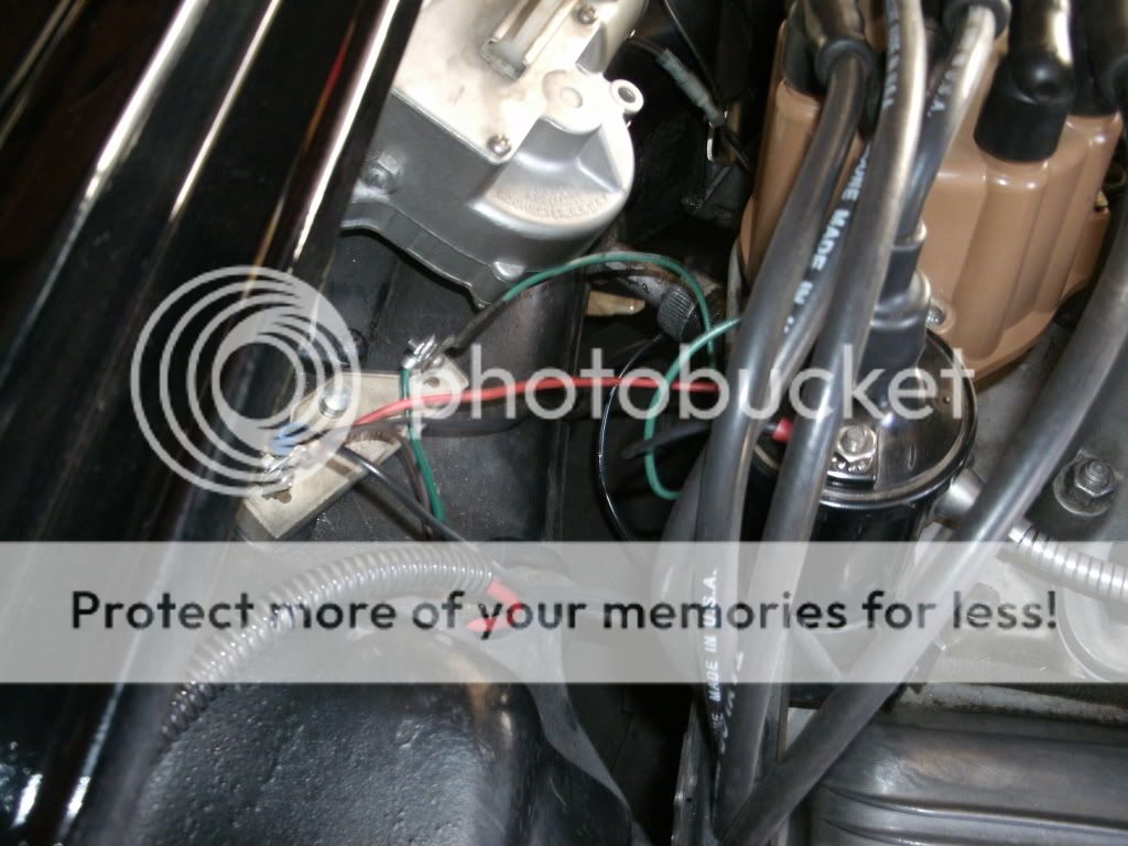
I am going from a Pertronix I to Pertronix III. In the photo below the current hook up has a green wire going from the + coil to the right (low voltage) side of the resister. Do I move the green wire from the right (low voltage side) resister to the left (12 volt side) and leave the other end connected to the positive side of the coil? Thanks

Team Owner

Joined: Aug 2007
Posts: 58,061
Likes: 7,146
Army
I don't see a green wire in your photo where I would normally expect the "low voltage" side of the ballast resistor. The photo is sort of upside down so I don't know what you consider "left" or "right"...normal convention is the driver's side is the left side. Its better to use "passenger" and "driver" designations.
Here is what you want to end up with....(see picture of my '61).
Basically you want BOTH the Pertronix power feed (usually a red wire) AND the positive side of the ignition coil going to "switched", full-time 12V from the ignition switch....whichever side of the resistor that is located. Remember the Ignitor III rev limiter is set to 5,500RPM by default (in case you want to change the max RPM limit).
Last edited by Frankie the Fink; Dec 3, 2011 at 07:17 PM.

Team Owner


Joined: Oct 2000
Posts: 38,897
Likes: 1,926
From: Washington Michigan

Team Owner
Joined: Aug 2007
Posts: 58,061
Likes: 7,146
Army
Generally true, however I ran my Pertronix II with the stock Delco coil for about 1-1/2 years with no problem with the ballast resistor bypassed.....maybe just the luck of the draw...
I DO run a FlameThrower III coil with the Pertronix III however. I would recommend the OP upgrade the coil to a 0.3 ohm or 0.6 ohm coil and then run the full 12V to it.
I DO run a FlameThrower III coil with the Pertronix III however. I would recommend the OP upgrade the coil to a 0.3 ohm or 0.6 ohm coil and then run the full 12V to it.
Thread Starter
Melting Slicks
Joined: Nov 2006
Posts: 2,618
Likes: 149
From: Anaheim California
If you look at the picture. The right side of the resister has a green wire with black tape on it (low voltage). That wire currently goes from the low voltage side of the resister to the + coil. The 12 volt side has the red wire that goes to the pertronix module.
I am not sure what to do with the green wire once I install the pertronix III. Do I just move the green wire from the low voltage side of the resister to the 12 volt side and the leave the other end connected to the positive coil? I don't think I would be removing this wire all together.
Right now my pertronix I has the red wire going to 12 volt resister. The black to - coil and the green wire from
+ coil to low voltage resister
Last edited by jtranger; Dec 3, 2011 at 08:07 PM. Reason: add
Team Owner
Joined: Oct 2000
Posts: 38,897
Likes: 1,926
From: Washington Michigan
If you look at the picture. The right side of the resister has a green wire with black tape on it (low voltage). That wire currently goes from the low voltage side of the resister to the + coil. The 12 volt side has the red wire that goes to the pertronix module.
I am not sure what to do with the green wire once I install the pertronix III. Do I just move the green wire from the low voltage side of the resister to the 12 volt side and the leave the other end connected to the positive coil? I don't think I would be removing this wire all together.
Right now my pertronix I has the red wire going to 12 volt resister. The black to - coil and the green wire from
+ coil to low voltage resister
I am not sure what to do with the green wire once I install the pertronix III. Do I just move the green wire from the low voltage side of the resister to the 12 volt side and the leave the other end connected to the positive coil? I don't think I would be removing this wire all together.
Right now my pertronix I has the red wire going to 12 volt resister. The black to - coil and the green wire from
+ coil to low voltage resister
Team Owner
Joined: Aug 2007
Posts: 58,061
Likes: 7,146
Army
Pretty sure those are from Jeff....best you hook up as John has said although if you call Pertronix they will give you conflicting info about including the ballast resistor (as I found out). I'd still upgrade the coil if it were me.
Tech Contributor


Joined: May 2005
Posts: 15,576
Likes: 118
From: Conroe Texas
Yeah that's from me.
In the bottom diagram the ballast resistor is simply serving as a junction block for the wiring. An alternative for the bottom configuration, which looks a bit cleaner under the hood, is to run the red Pertronix wire directly to the + terminal on the coil, reducing the number of wires that are all hanging out at the single connection on the ballast.
In the bottom diagram the ballast resistor is simply serving as a junction block for the wiring. An alternative for the bottom configuration, which looks a bit cleaner under the hood, is to run the red Pertronix wire directly to the + terminal on the coil, reducing the number of wires that are all hanging out at the single connection on the ballast.
Corvette Stories
The Best of Corvette for Corvette Enthusiasts

Every 2027 Corvette Engine Explained
Joe Kucinski
Designer Imagines A Corvette That Looks More Like a Corvette Than the Corvette
Verdad Gallardo
10 Ugly Corvettes That We Still Kinda Love
Joe Kucinski
Top 10 Most Expensive Corvettes Ever Sold on Bring A Trailer
Brett Foote
10 Things Every Corvette Owner Needs (2026 Edition)
Michael S. Palmer
8 Most "Only Corvette Owners Understand" Quirks and Problems
Pouria Savadkouei
10 Reasons the C6 Z06 is Still A Performance Benchmark After 20 Years
Joe Kucinski
How Much Horsepower Every Corvette Engine "LOST" in 1972
Joe Kucinski
Top 10 DOs and DON'Ts for Protecting Your Convertible Top!
Michael S. Palmer
Thread Starter
Melting Slicks
Joined: Nov 2006
Posts: 2,618
Likes: 149
From: Anaheim California
Yeah that's from me.
In the bottom diagram the ballast resistor is simply serving as a junction block for the wiring. An alternative for the bottom configuration, which looks a bit cleaner under the hood, is to run the red Pertronix wire directly to the + terminal on the coil, reducing the number of wires that are all hanging out at the single connection on the ballast.
In the bottom diagram the ballast resistor is simply serving as a junction block for the wiring. An alternative for the bottom configuration, which looks a bit cleaner under the hood, is to run the red Pertronix wire directly to the + terminal on the coil, reducing the number of wires that are all hanging out at the single connection on the ballast.
Thanks Guys!
Tech Contributor
Joined: May 2005
Posts: 15,576
Likes: 118
From: Conroe Texas
Noooo, if you do that then your coil won't get power from the ignition switch circuit. Leave that wire in place and connect the red pertronix wire to either the + coil or the resistor where the + coil wire terminates.
Team Owner
Joined: Oct 2000
Posts: 38,897
Likes: 1,926
From: Washington Michigan
Tech Contributor
Joined: May 2005
Posts: 15,576
Likes: 118
From: Conroe Texas
That will have his Pertronix module running on resistor-reduced current, which isn't a good idea. The red wire should go to the 12V (ignition switch) side of the resistor. The other (resistor-reduced) side of the resistor should feed the (+) side of his stock coil. His setup should be exactly like the center diagram.
Last edited by 62Jeff; Dec 4, 2011 at 02:44 PM.
Thread Starter
Melting Slicks
Joined: Nov 2006
Posts: 2,618
Likes: 149
From: Anaheim California
That will have his Pertronix module running on resistor-reduced current, which isn't a good idea. The red wire should go to the 12V (ignition switch) side of the resistor. The other (resistor-reduced) side of the resistor should feed the (+) side of his stock coil. His setup should be exactly like the center diagram.
Tech Contributor
Joined: May 2005
Posts: 15,576
Likes: 118
From: Conroe Texas
John, I am aware that everything is hooked up correctly now for the stock coil. I am going to the pertronix III with pertronix III coil. Where does the wire that is now going from the + coil to low voltage go when I change to the pertronix III igniter and coil? That was my original question.