Wiring Harness
 12-06-2011, 07:23 PM
#1
Instructor

Thread Starter
Member Since: Feb 2011
Location: Crestview Fl
Posts: 207
Likes: 0
Received 0 Likes
on
0 Posts
Hey Gang, I need a little help wiring.
There is a large black wire with white strip coming off my the main harness (Lectric Limited) attached to the fuse box. It appears to be used as a ground for FI. Did anyone run across this issue? Does anyone have any idea if it needs to be grounded and where if you are not Fuel Injected?
Thanks
Rog
There is a large black wire with white strip coming off my the main harness (Lectric Limited) attached to the fuse box. It appears to be used as a ground for FI. Did anyone run across this issue? Does anyone have any idea if it needs to be grounded and where if you are not Fuel Injected?
Thanks
Rog
 12-06-2011, 07:28 PM
#2
Tech Contributor


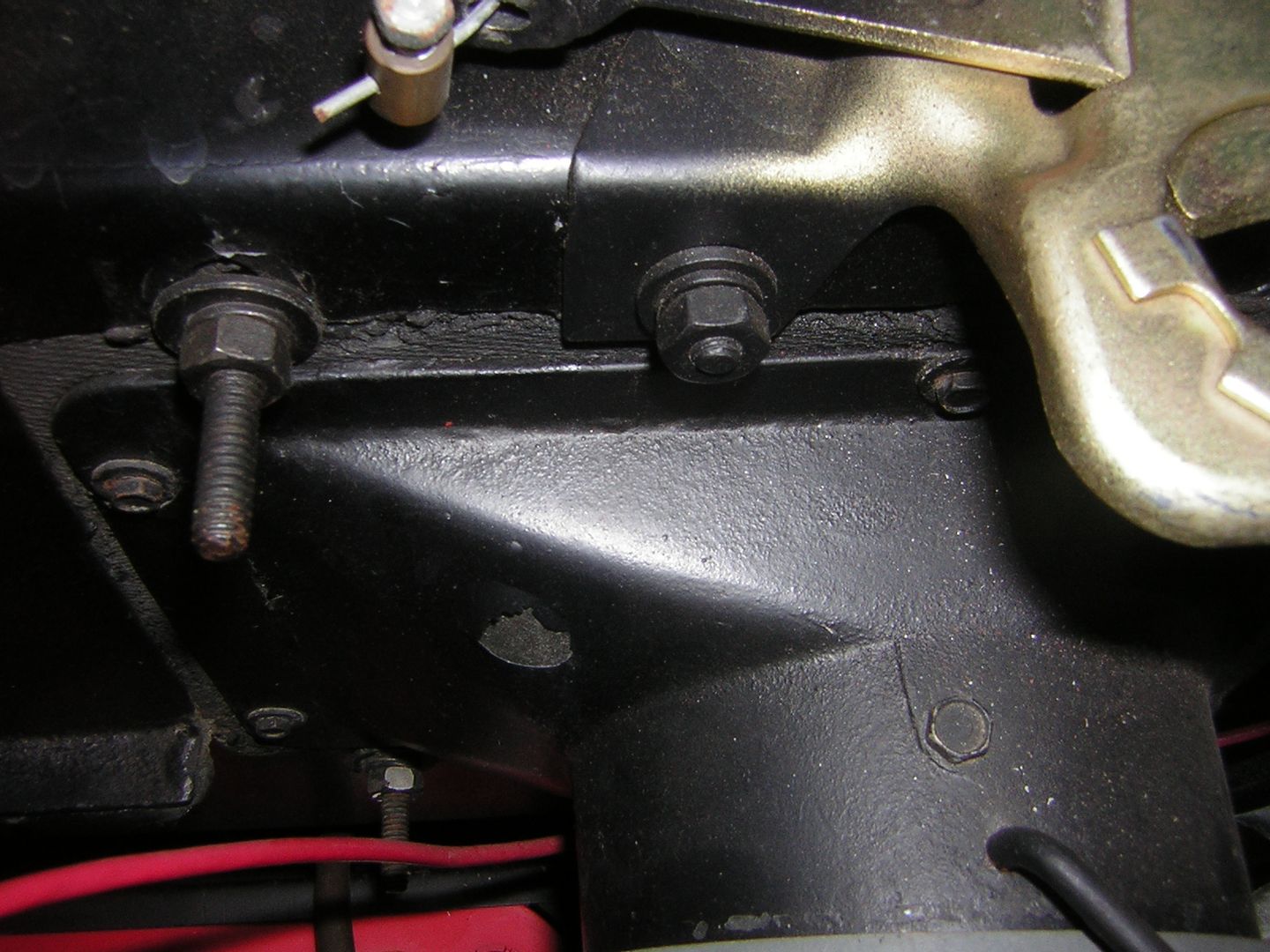
At first blush sounds like the ground wire that connects to driver's side valve cover at the rear inner mounting screw.
Last edited by 62Jeff; 12-06-2011 at 07:32 PM.
12-06-2011, 07:52 PM
#3
Team Owner


Jeff is no doubt right but the Dr. Rebuild schematic should clear it up for sure.
12-06-2011, 08:31 PM
#4
Instructor
Thread Starter
Member Since: Feb 2011
Location: Crestview Fl
Posts: 207
Likes: 0
Received 0 Likes
on
0 Posts
That is what the wire looks like, however it appears on the Dr rebuild Schematic it is for Fuel Injection. I guess it couldn't hurt to have another ground if that is what it is?
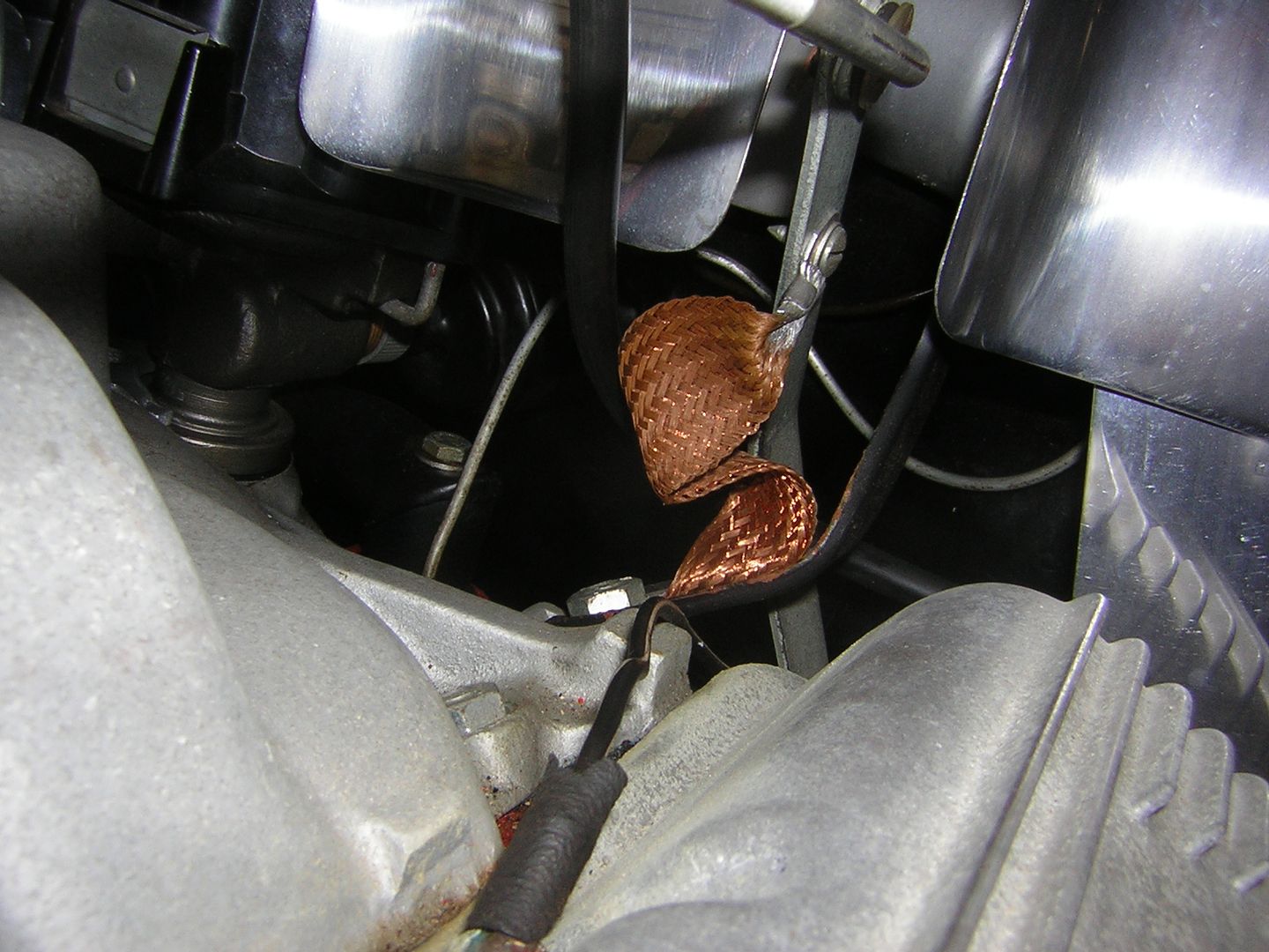
Jeff, by the way what is that copper ground you have to the rear of the valve cover. From what point to what point does that one attach?
Thanks
Rog
Jeff, by the way what is that copper ground you have to the rear of the valve cover. From what point to what point does that one attach?
Thanks
Rog
12-06-2011, 08:56 PM
#5
Tech Contributor
 12-06-2011, 11:55 PM
#6
Instructor
Thread Starter
Member Since: Feb 2011
Location: Crestview Fl
Posts: 207
Likes: 0
Received 0 Likes
on
0 Posts
Thats for the photo. I have a ground strip kit and was trying to figure out where all the grounds went. So it appears the black wire with the white strip goes to the DR side valve cover screw? Do you know if that is where it went orginally?
Thanks
Rog
Thanks
Rog
12-07-2011, 12:07 AM
#7
Instructor
Thread Starter
Member Since: Feb 2011
Location: Crestview Fl
Posts: 207
Likes: 0
Received 0 Likes
on
0 Posts
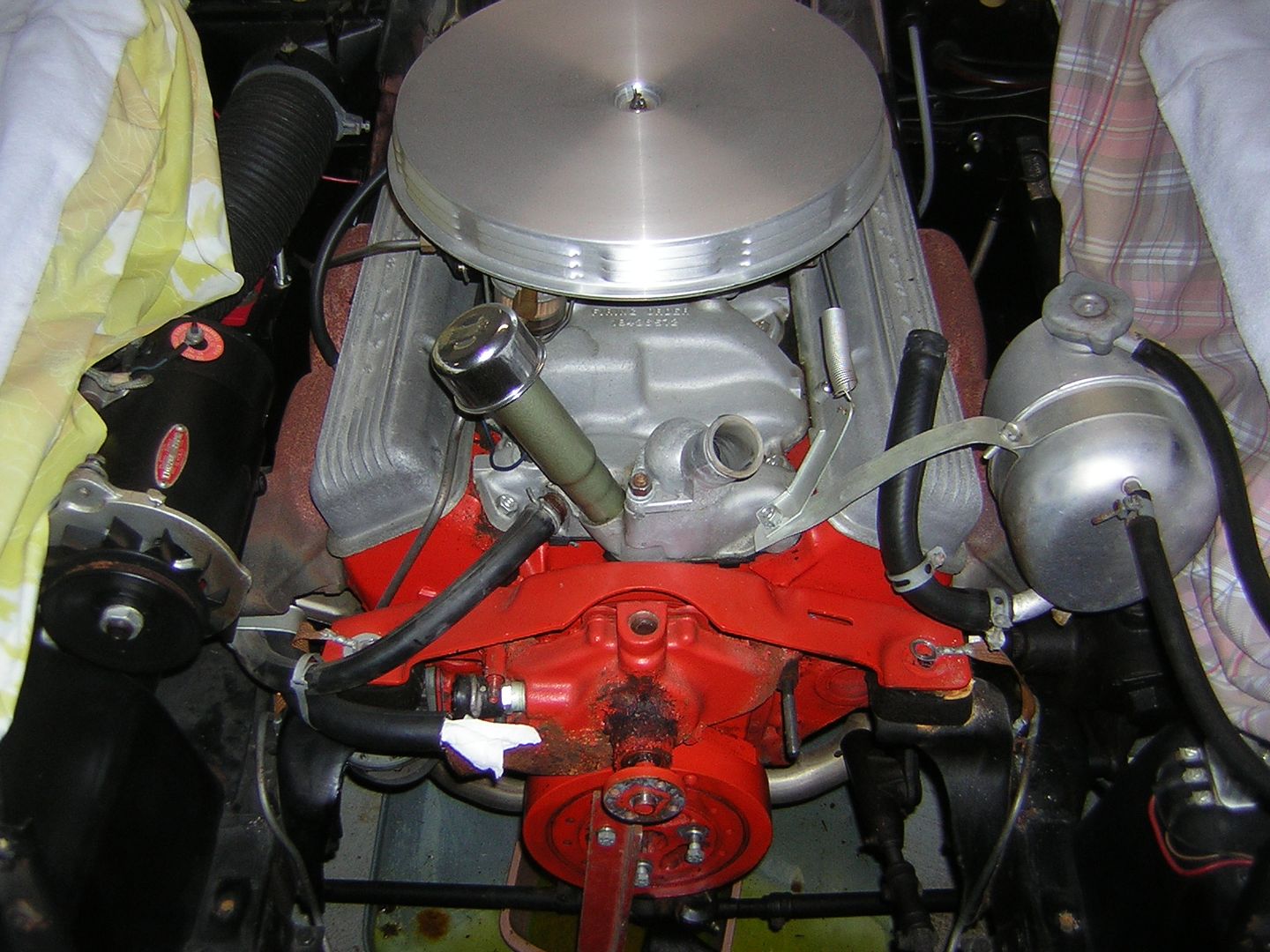
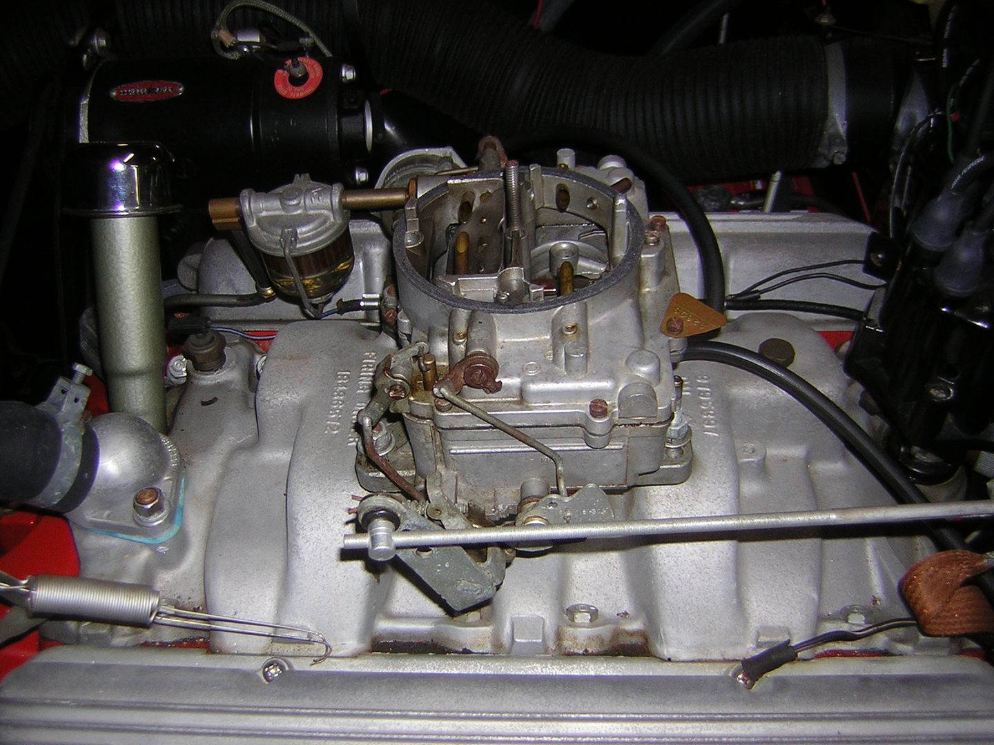
By the way do you guys have any idea how many grounds there are in the engine bay. I know I have one going from the PS Front motor mount to the frame. As your picture indicates above, there is one from the throttle linkage to the DS manifold bolt, and the black/wire to the DS valve cover. Is there anymore?
Thanks
Rog
Thanks
Rog
12-07-2011, 05:17 PM
#8
Instructor
Thread Starter
Member Since: Feb 2011
Location: Crestview Fl
Posts: 207
Likes: 0
Received 0 Likes
on
0 Posts
Finished the wiring today. Now I am waiting for the gauges to return so I can put the cluster housing back in the dash. Cant wait to get them back and check out the wiring to determine if it all works. It sure looks like alot less wiring went in than came out.
12-07-2011, 05:32 PM
#9
Team Owner
I'm sure it'll be fine...you've been extraordinarily careful and checked with the online gurus at each step. As I've said make sure the 30 AMP ATC ammeter fuse is in place first then put the individual fuses in, one-at-a-time, observing things as you go. Most schematics on C1s show the ammeter wires reversed...won't hurt anything if they are...ammeter will just read backwards...so then swap the wires and rock on.
Never hurts to have a fire extinguisher nearby...Halitron extinguishers are best.
Never hurts to have a fire extinguisher nearby...Halitron extinguishers are best.
12-07-2011, 05:41 PM
#10
Instructor
Thread Starter
Member Since: Feb 2011
Location: Crestview Fl
Posts: 207
Likes: 0
Received 0 Likes
on
0 Posts
Got the 30 Amp in the Ammeter and an inline to the cigarette lighter. I was looking at one of the guage restoration tip lines and they indicated putting another inline to the clock. A low amp 2.5. Are you familiar with that recommendation?
Rog
Rog
12-07-2011, 07:54 PM
#12
Team Owner
Yes - if you have a factory clock...the points can stick together and shunt current through the clock mechanism overheating the wiring. A fuse wouldn't hurt.
If you run a quartz repro clock then you can leave it alone.
If you run a quartz repro clock then you can leave it alone.
12-07-2011, 08:10 PM
#13
Tech Contributor
As your picture indicates above, there is one from the throttle linkage to the DS manifold bolt, and the black/wire to the DS valve cover. Is there anymore?
Thanks
Rog
Thanks
Rog
Jeff
12-07-2011, 09:05 PM
#14
Instructor
Thread Starter
Member Since: Feb 2011
Location: Crestview Fl
Posts: 207
Likes: 0
Received 0 Likes
on
0 Posts
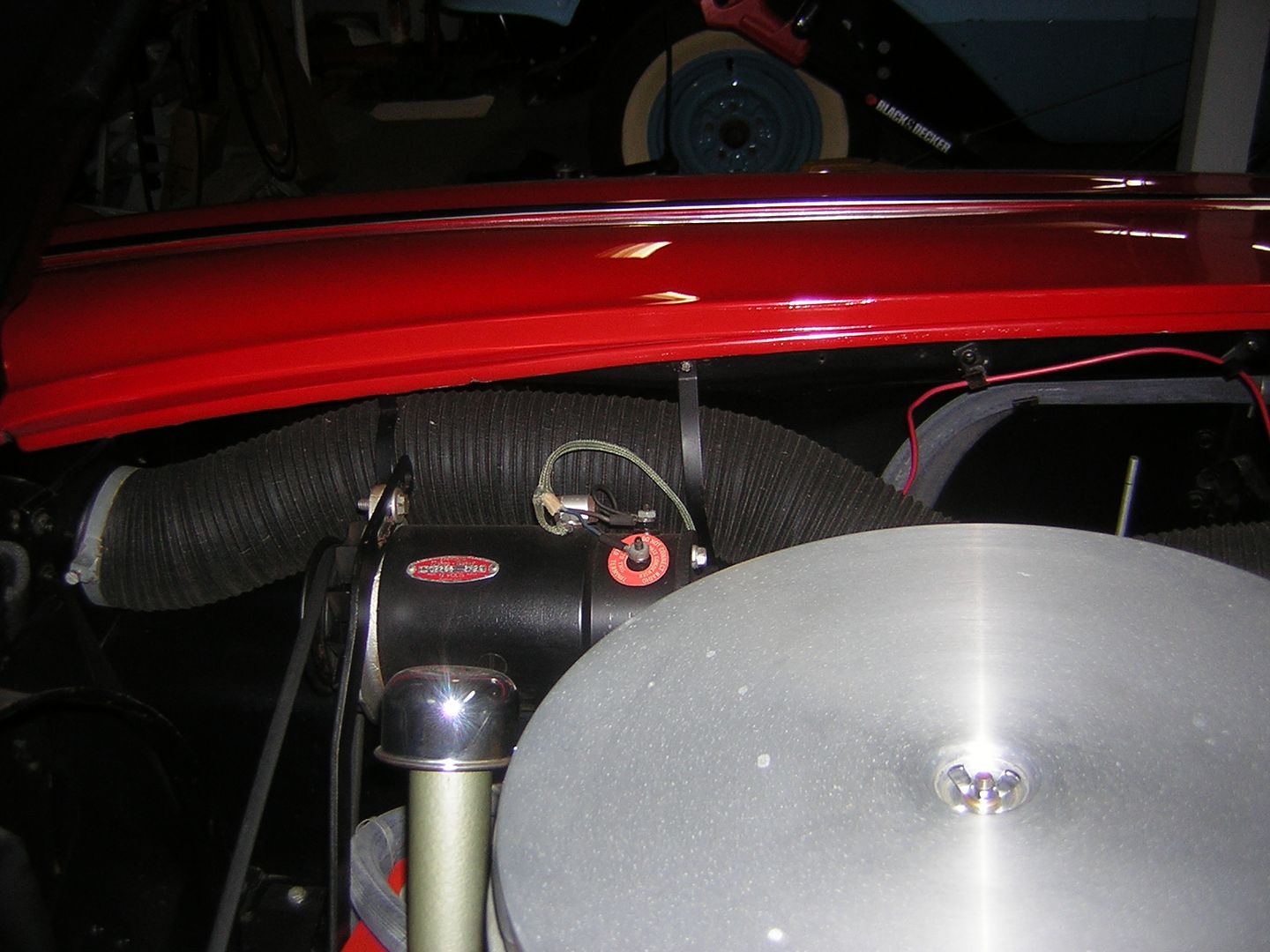
Good picture. I have the one that runs to the wiper motor mount to the valve cover attached. But it appears there is another one that runs to the radio? I took out my wonderbar, and have an aftermarket radio. However, I could ground the aftermarket like the orginal. So the wiper ground and the radio ground both attach to the rear PS valve cover bolt?
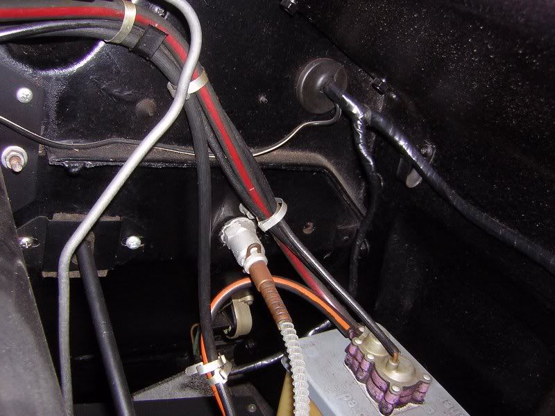
I have one other question. The Regualtor (red) wire. I have it under the fresh air hose up along the top of the PS fender drively above the VR it goes straight down to the VR. Is that right, because it looks a little crappie. I also have the black and white large ground wire coming out of the same hole in the firewall as the headlight/horn relay wire along the front of the firewall over the steering shaft to the valve cover rear screw. Is that the way your is?
Rog
Thanks
Rog
12-07-2011, 09:27 PM
#15
Tech Contributor
Good picture. I have the one that runs to the wiper motor mount to the valve cover attached. But it appears there is another one that runs to the radio? I took out my wonderbar, and have an aftermarket radio. However, I could ground the aftermarket like the orginal.
So the wiper ground and the radio ground both attach to the rear PS valve cover bolt?
I have one other question. The Regualtor (red) wire. I have it under the fresh air hose up along the top of the PS fender drively above the VR it goes straight down to the VR. Is that right, because it looks a little crappie.
I also have the black and white large ground wire coming out of the same hole in the firewall as the headlight/horn relay wire along the front of the firewall over the steering shaft to the valve cover rear screw. Is that the way your is?
Rog
Rog
 12-08-2011, 06:39 PM
#17
Instructor
Thread Starter
Member Since: Feb 2011
Location: Crestview Fl
Posts: 207
Likes: 0
Received 0 Likes
on
0 Posts
Look familiar? It is good to have a few friends out there that don't mind helping out on the learning curve.
Hey, Frank/Jef
I know I aske this question, however when I looked it had two answers.
The Green wire on the PS of the ballast resistor normally connects to the (R or C) on the starter. One response was not to connect it at the bottom since I did not need it. The other was to connect it so I did not get confused later concerning where it should be attached.
Now the (R) on the starter is only activated with 12 volt when cranking. If that is the case does or would it make a difference connecting it. In my humble opionion that would shoot an extra 12 to the ballast resistor to the coil when cranking. With the key is on and not cranking I would think the brown wire (hot) would send 12 volts through the balast resistor to the (r) side of the starter? Would that hurt anything?
Rog
12-08-2011, 07:46 PM
#18
Team Owner
OK - a little electronic theory...there is ALWAYS 12V on the DS of the ballast resistor when the ignition is on; connecting the C/R starter wire to the PS of the ballast resistor provides 12V as well (but ONLY during cranking). So in this situation there is 12V on BOTH sides of the ballast resistor so there is no electrical "potential" and no current flows through the resistor -- so it has no effect.
My starter wire has been hooked up for two years - it has no effect on anything.
My starter wire has been hooked up for two years - it has no effect on anything.
12-08-2011, 07:55 PM
#19
Instructor
Thread Starter
Member Since: Feb 2011
Location: Crestview Fl
Posts: 207
Likes: 0
Received 0 Likes
on
0 Posts
I can sleep well tonight! I hate to make things complicated, however it is alway better to ask twice so you dont burn once.
I know this much. I will be the expert around my parts thanks to Obi-Won Kenobi Frank
I know this much. I will be the expert around my parts thanks to Obi-Won Kenobi Frank
12-09-2011, 07:41 AM
#20
Team Owner
Thanks - just don't ask me about paint, engine overhauls, transmission internals or front end components.
Most everything else I've touched, screwed up and then figured out how to do it right later on.
Most everything else I've touched, screwed up and then figured out how to do it right later on.