









Oh No ... Steering Column Failure !!!
Le Mans Master


Joined: Oct 2005
Posts: 6,247
Likes: 471
From: Glen Allen, VA

My money would be on the c clip also. I've actually driven mine VERY slowly around the driveway with the c clip out. Just as said, you can pull hte wheel right out, but it also goes right back in, you just have to hold it there.

Race Director


Joined: Apr 1999
Posts: 11,520
Likes: 13
From: CORVETTE 77 385 C.I. TEXAS
A long time ago the steering wheel came off a 57 Chevy w/ aftermarket st. wh. about 60 (traffic lights leaving town) on 4 lane 2 way hwy. because there was no nut on top. Wound up in the median. At least I was able to put it back on for the about 50 mile hwy. drive home.
Jim
Sounds good! Very good info.!

I have adj. the tele. running on mine & some time ago on an El Dorado w/ a similar column.
...
The clip in the above picture prevents the upper steering shaft (with the steering wheel and hub) from pulling out of the steering column just as you experienced. As long as the telescope lock is secure the upper shaft cannot move. Release the telescope lock (without the clip) and you can experience exactly what happened to you.
...
Jim
The clip in the above picture prevents the upper steering shaft (with the steering wheel and hub) from pulling out of the steering column just as you experienced. As long as the telescope lock is secure the upper shaft cannot move. Release the telescope lock (without the clip) and you can experience exactly what happened to you.
...
Jim
Sounds good! Very good info.!
I have adj. the tele. running on mine & some time ago on an El Dorado w/ a similar column.

Drifting


Joined: Oct 2004
Posts: 1,255
Likes: 7
From: Coralville Iowa
I went and looked at a 68 vert the other day as a project. I loosened the tele lock and had the same thing happen. The whole wheel and shaft puled out about 8 inches. I looked at the seller and asked "Has this happened before?" He looked at me somewhat dumbfounded and said " No..... I think you pulled to hard." I laughed and walked away.

Thread Starter
Pro

Joined: Aug 2001
Posts: 667
Likes: 3
From: College Station TX
Thread Starter
Pro
Joined: Aug 2001
Posts: 667
Likes: 3
From: College Station TX
Jim
Finally had the time ( and courage ) to look at my column today ... the c-clip is still in place !!! It's as if - somehow - the wedge got so loose that the inner shaft ( attached to steering hub ) got loose enough to allow the separation ... is that possible ???
Mike
Finally had the time ( and courage ) to look at my column today ... the c-clip is still in place !!! It's as if - somehow - the wedge got so loose that the inner shaft ( attached to steering hub ) got loose enough to allow the separation ... is that possible ???
Mike
I am certainly glad that you are safe and OK from your experience. I am quite sure that the problem with your T&T steering column is a missing c-clip.
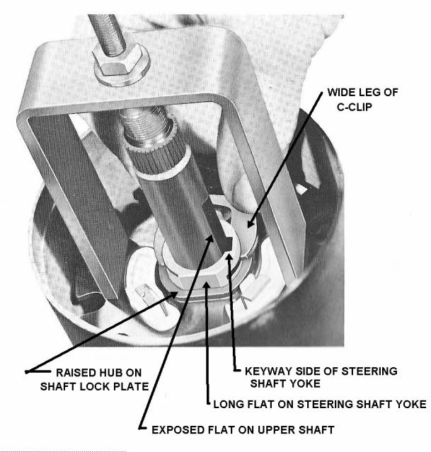
The clip in the above picture prevents the upper steering shaft (with the steering wheel and hub) from pulling out of the steering column just as you experienced. As long as the telescope lock is secure the upper shaft cannot move. Release the telescope lock (without the clip) and you can experience exactly what happened to you.
The missing part is GM 7819976 called a retainer. There should be another plastic part (also called a retainer) that should be installed on top of the clip. It is GM 7808385. The plastic part insures that the clip cannot migrate out of its slot. It also acts to insulate the big spring on the cancelling cam and prevents your horn from blowing continuously. Both parts are still available through GM dealers and also through most Corvette suppliers.
You will need a steering wheel puller to seperate the steering wheel hub from the upper steering shaft. Then you can install the upper shaft into the steering column shaft as shown in the above picture. You will need to lock the upper shaft in place so that you can use a special tool to compress the locking plate and install the missing clip.
The steering wheel hub puller and the locking plate compression tool can be purchased, borrowed, or rented from most major automotive stores.
Full instructions on removing and installing the upper column T&T parts can be found at:
http://jimshea.corvettefaq.com/wp-co...ev15jn2009.pdf
Again sorry to hear of your experience but I am glad that everyone and everything is OK.
Jim
The clip in the above picture prevents the upper steering shaft (with the steering wheel and hub) from pulling out of the steering column just as you experienced. As long as the telescope lock is secure the upper shaft cannot move. Release the telescope lock (without the clip) and you can experience exactly what happened to you.
The missing part is GM 7819976 called a retainer. There should be another plastic part (also called a retainer) that should be installed on top of the clip. It is GM 7808385. The plastic part insures that the clip cannot migrate out of its slot. It also acts to insulate the big spring on the cancelling cam and prevents your horn from blowing continuously. Both parts are still available through GM dealers and also through most Corvette suppliers.
You will need a steering wheel puller to seperate the steering wheel hub from the upper steering shaft. Then you can install the upper shaft into the steering column shaft as shown in the above picture. You will need to lock the upper shaft in place so that you can use a special tool to compress the locking plate and install the missing clip.
The steering wheel hub puller and the locking plate compression tool can be purchased, borrowed, or rented from most major automotive stores.
Full instructions on removing and installing the upper column T&T parts can be found at:
http://jimshea.corvettefaq.com/wp-co...ev15jn2009.pdf
Again sorry to hear of your experience but I am glad that everyone and everything is OK.
Jim

Le Mans Master


Joined: Jul 2000
Posts: 6,001
Likes: 112
From: Saginaw Michigan
Mike,
Are you sure that the c-clip was fully installed? It should have been in place with a plastic retainer on top of it.
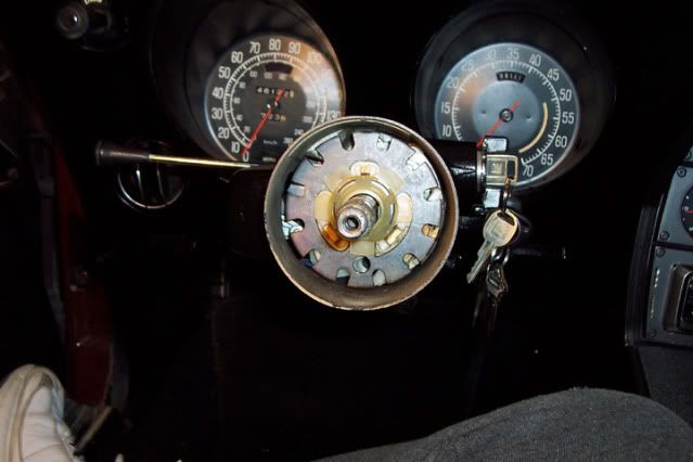
I have a loose yoke shaft, wedge, c-clip, locking rod, and upper shaft. When I assemble them, and the wedge is in place, it will not pass under the c-clip and allow the upper shaft to come out of the steering column, (even with the locking rod missing.)
Jim
Are you sure that the c-clip was fully installed? It should have been in place with a plastic retainer on top of it.
I have a loose yoke shaft, wedge, c-clip, locking rod, and upper shaft. When I assemble them, and the wedge is in place, it will not pass under the c-clip and allow the upper shaft to come out of the steering column, (even with the locking rod missing.)
Jim
Last edited by Jim Shea; Sep 7, 2009 at 09:09 AM.
Corvette Stories
The Best of Corvette for Corvette Enthusiasts

Top 10 Most Explosive Corvettes Ever Made: Power-to-Weight Ratio Ranked!
Joe Kucinski
150 hp to 1,250 hp: Every Corvette Generation Compared by the Specs That Matter
Joe Kucinski
8 Coolest Corvette Pace Cars (and Replicas) of All Time
Verdad Gallardo
Top 10 Corvette Engines RANKED by Peak Torque (70+ Years of Muscle!)
Joe Kucinski
Corvette ZR1X Will Be Pacing the Indy 500, And Could Probably Race, Too!
Verdad Gallardo
Top 10 Corvettes Coming to Mecum Indy 2026!
Brett Foote
Top 10 C9 Corvette MUST-HAVES to Fix These C8 Generation Flaws!
Michael S. Palmer
10 Revolutionary 'Corvette Firsts' Most People Don't Know
Joe Kucinski
5 Reasons to Upgrade to an LS6-Powered Corvette; 5 Reasons to Stay LT2
Michael S. Palmer
8th Gear

Joined: Jan 2007
Posts: 8
Likes: 0
From: Cumming GA
thank you thank you thank you
Jim (others),
Re 1978 Corvette Steering/turn signal reassembly
I’ve been digging thru all your postings about the Corvette steering assemblies. Thanks so much for your work, and sharing it with the world. I do need a few more details with getting this all back together. As I posted earlier, I took my sons steering wheel off all the way down to the turn signal assembly. It had stopped working and I was troubleshooting as to what part failed. When I removed that ‘C’ clip and the springs pushed the “shaft lock plate” up, I knew I was in trouble….but anyway
I found the turn signal problem; there is a flat metal arm the goes from the lever to the plastic turn signal switch…it is broke. I found it at Ecklers (39212) for $16…do you know if GM still has this part? I would like to go ahead and fix it and not have to wait for shipping…..
Now, about getting this all back together….I cannot compress the spring/lock plate assembly enough to get the “C” clip in…when I press it all down, the shaft with the groove for the clip seems to move down also and I cannot clear the groove….I looked at the “steering column lockplate compressor” tool (including the instruction for making one) and believe this is what I need. What I don’t understand is what it attaches to so I can compress the plate/spring. I am reading your paper “ttcolumndr_1rev15jn2009.pdf” but don’t have the drawings/pics that it refers to? It looks like some how I use the inner shaft to screw into and lock it in place with the telescopic locking ring? But don’t see all that…I will be trying this all in the morning and maybe it will make better sense when it is in front of me..
Thanks again,
Brian
Re 1978 Corvette Steering/turn signal reassembly
I’ve been digging thru all your postings about the Corvette steering assemblies. Thanks so much for your work, and sharing it with the world. I do need a few more details with getting this all back together. As I posted earlier, I took my sons steering wheel off all the way down to the turn signal assembly. It had stopped working and I was troubleshooting as to what part failed. When I removed that ‘C’ clip and the springs pushed the “shaft lock plate” up, I knew I was in trouble….but anyway
I found the turn signal problem; there is a flat metal arm the goes from the lever to the plastic turn signal switch…it is broke. I found it at Ecklers (39212) for $16…do you know if GM still has this part? I would like to go ahead and fix it and not have to wait for shipping…..
Now, about getting this all back together….I cannot compress the spring/lock plate assembly enough to get the “C” clip in…when I press it all down, the shaft with the groove for the clip seems to move down also and I cannot clear the groove….I looked at the “steering column lockplate compressor” tool (including the instruction for making one) and believe this is what I need. What I don’t understand is what it attaches to so I can compress the plate/spring. I am reading your paper “ttcolumndr_1rev15jn2009.pdf” but don’t have the drawings/pics that it refers to? It looks like some how I use the inner shaft to screw into and lock it in place with the telescopic locking ring? But don’t see all that…I will be trying this all in the morning and maybe it will make better sense when it is in front of me..
Thanks again,
Brian
Le Mans Master
Joined: Jul 2000
Posts: 6,001
Likes: 112
From: Saginaw Michigan
You need to lock the upper shaft from telescoping by installing the original star screw and tightening it against the locking rod and wedge inside the shaft. With the upper shaft locked, the compressor tool will work effectively. If the star screw interferes with the tool, go to a hardware store and purchase a 5/16-18UNC set screw to lock the shaft. (Just remember to remove the set screw and replace it with the star screw when you are finished.
The crossover arm is GM #7827038 and is still available through GM dealers.
Jim
The crossover arm is GM #7827038 and is still available through GM dealers.
Jim

Team Owner


Joined: Sep 2004
Posts: 49,696
Likes: 9
From: Life isn't about waiting for the Storm to pass, it's about learning to dance in the Rain.
8th Gear
Joined: Jan 2007
Posts: 8
Likes: 0
From: Cumming GA
I'm confused, concerning the turn signal canceling ring. I see conflicting pics/diagrams:
-The plastic canceling ring has 3 raised grooves that fit in the steel plate, 2 long and one short
- the ring also has a flat that matches the flat on the shaft.
Problem is the Canceling ring can go in either orientation:
a) the short raised groove up (puts canceling cams to the left at 10oclock)
or
b) the short raised cam down (puts canceling cams to the Right at 5oclock)
(yes, I screwed up not noting it before taking out, I assumed it would only go in one way)
The pic3 shows the clip going in from the top and the 2 long slots at the bottom...
my clip will only go in from the bottom...so i'm confused
thx,
Brian
-The plastic canceling ring has 3 raised grooves that fit in the steel plate, 2 long and one short
- the ring also has a flat that matches the flat on the shaft.
Problem is the Canceling ring can go in either orientation:
a) the short raised groove up (puts canceling cams to the left at 10oclock)
or
b) the short raised cam down (puts canceling cams to the Right at 5oclock)
(yes, I screwed up not noting it before taking out, I assumed it would only go in one way)
The pic3 shows the clip going in from the top and the 2 long slots at the bottom...
my clip will only go in from the bottom...so i'm confused
thx,
Brian
Le Mans Master
Joined: Jul 2000
Posts: 6,001
Likes: 112
From: Saginaw Michigan
If you follow the above picture showing the compressor tool pressing down on the locking plate you can't go wrong. It also shows the correct orientation of the upper shaft to lower shaft and the correct orientation of the upper shaft to the locking plate.
The locking plate goes on the shaft with the hub of the plate sticking up toward you. The cancelling cam fits into the underside of that locking plate. The three brass contacts are sticking up through the plate towards you. Those three brass contacts will touch the large conical spring and makes the horn grounding circuit.
Jim
The locking plate goes on the shaft with the hub of the plate sticking up toward you. The cancelling cam fits into the underside of that locking plate. The three brass contacts are sticking up through the plate towards you. Those three brass contacts will touch the large conical spring and makes the horn grounding circuit.
Jim
8th Gear
Joined: Jan 2007
Posts: 8
Likes: 0
From: Cumming GA
If you follow the above picture showing the compressor tool pressing down on the locking plate you can't go wrong. It also shows the correct orientation of the upper shaft to lower shaft and the correct orientation of the upper shaft to the locking plate.
The locking plate goes on the shaft with the hub of the plate sticking up toward you. The cancelling cam fits into the underside of that locking plate. The three brass contacts are sticking up through the plate towards you. Those three brass contacts will touch the large conical spring and makes the horn grounding circuit.
Jim
The locking plate goes on the shaft with the hub of the plate sticking up toward you. The cancelling cam fits into the underside of that locking plate. The three brass contacts are sticking up through the plate towards you. Those three brass contacts will touch the large conical spring and makes the horn grounding circuit.
Jim
It is all back together, my sons off to work to make money to buy parts..
I will order a new "Signal Switch Arm" and I will also need a new "Carrier Snap Ring Retainer" (mine has some tabs broken off and it is very brittle..
Once those parts are in I will have to do it all over again....
A question on the spring and the horn contacts. The spring rests directly on the contacts, It looks like that spring would catch the horn contacts, am I missing something?
While assembling it I could hear the horn? relay clicking as I bumped the spring putting it in and out..but no horn
the horn has never worked.
part b of this project will be getting the hurn working at the same time I fix the turnsignal switch..
thank you all for your help

Intermediate
Joined: Oct 2007
Posts: 27
Likes: 0
From: Chicago IL
Geez! Glad that worked out ok. You must be doing something right! I have a nightmare every week or so about that happeneing on my daily driver Caprice wagon. Never has happened, but I still have the same dream. Headed off the road, steering wheel spinning free in my hands.

Pro
Joined: Nov 2007
Posts: 741
Likes: 1
From: Woodstock GA
A long time ago the steering wheel came off a 57 Chevy w/ aftermarket st. wh. about 60 (traffic lights leaving town) on 4 lane 2 way hwy. because there was no nut on top. Wound up in the median. At least I was able to put it back on for the about 50 mile hwy. drive home.
Jim
Sounds good! Very good info.!
I have adj. the tele. running on mine & some time ago on an El Dorado w/ a similar column.
Jim
Sounds good! Very good info.!
I have adj. the tele. running on mine & some time ago on an El Dorado w/ a similar column.
Last edited by 1981Z06Vette; Sep 23, 2009 at 12:02 PM. Reason: typo

Racer
Joined: Oct 2009
Posts: 280
Likes: 1
From: cleveland Ohio
i had a similar experence with a 95 mustang gt. the steering shaft under the dash seperated, its a two piece shaft, one slides into the other, and they slid apart leaving me with a wheel that just spun free. lucky i was only going 15 mph,about to pull into my driveway,scarred me to death. ford said they would not help me. but i do know the sick feeling of no steering.i have a 68 t top vette with telescopic column, so i will take alook at mine someday. good luck to you. p.s. good lookin out jim shea cheers tom g.
Le Mans Master
Joined: Jul 2000
Posts: 6,001
Likes: 112
From: Saginaw Michigan
With respect to your question a couple posts back.
"A question on the spring and the horn contacts. The spring rests directly on the contacts, It looks like that spring would catch the horn contacts, am I missing something?"
The big spring will rotate with the steering wheel hub, the toothed locking plate, as well as the lower horn contact. They all rotate together. So once in place, the big spring should always be in direct contact with one (if not all three) of the brass contacts sticking up through the locking plate. The plastic retainer should also prevent any part of the spring from touching the metal locking plate and causing the horn to blow continuously.
Jim
"A question on the spring and the horn contacts. The spring rests directly on the contacts, It looks like that spring would catch the horn contacts, am I missing something?"
The big spring will rotate with the steering wheel hub, the toothed locking plate, as well as the lower horn contact. They all rotate together. So once in place, the big spring should always be in direct contact with one (if not all three) of the brass contacts sticking up through the locking plate. The plastic retainer should also prevent any part of the spring from touching the metal locking plate and causing the horn to blow continuously.
Jim

Intermediate
Joined: Mar 2009
Posts: 48
Likes: 0
From: Southlake Texas
The cancel cam does not go on either direction!!!!! On the shaft that the cancel cam fits over there are two flats. One is deeper than the other except on '69 and maybe early '70.
The cancel cam has a bit of a built up spot in the center. That built up spot goes on the longest flat. The center of the lock ring has a raised spot on one side. That raised area goes up! Putting one together correctly makes thing go alot better. Questions....I got answers. I understand 69 1st design, 69second thru '71, 72-74, 75-6, 77, 78 first design, 78 second design, 78 third design thru 79 1st design, 79 second thru 80 and 81-82. All are different in many areas. corvette columns....that's what I do for a living.
The cancel cam has a bit of a built up spot in the center. That built up spot goes on the longest flat. The center of the lock ring has a raised spot on one side. That raised area goes up! Putting one together correctly makes thing go alot better. Questions....I got answers. I understand 69 1st design, 69second thru '71, 72-74, 75-6, 77, 78 first design, 78 second design, 78 third design thru 79 1st design, 79 second thru 80 and 81-82. All are different in many areas. corvette columns....that's what I do for a living.