






Door ajar switch electical connectors...

Thread Starter
Safety Car


Joined: Oct 2006
Posts: 3,993
Likes: 9
From: Gig Harbor WA
 Door ajar switch electical connectors...
I have new switches and new electrical terminals.....
The terminals have a U-bend at the end. When I shove the new terminals into the slot in the new switches, does it matter which way the U-bend goes.
Looks like the U-bend is supposed to help keep the terminal end from sliding out when the switch compresses and decompresses. I tried it both ways and the terminal slides out either way I install it.
Any help much appreciated!
Rob
The terminals have a U-bend at the end. When I shove the new terminals into the slot in the new switches, does it matter which way the U-bend goes.
Looks like the U-bend is supposed to help keep the terminal end from sliding out when the switch compresses and decompresses. I tried it both ways and the terminal slides out either way I install it.
Any help much appreciated!
Rob

Le Mans Master


Joined: Oct 2006
Posts: 7,123
Likes: 433
From: Gladstone MO
C3 of Year Finalist (appearance mods) 2019
I replaced a couple of those terminals on the 74 when I replaced the harness. Looked to me like the best way was with the open side of the U facing away from the center, and then that open end hooking over the edge. May not be correct, but it looked to me like the way to get it to work.
Thread Starter
Safety Car
Joined: Oct 2006
Posts: 3,993
Likes: 9
From: Gig Harbor WA
I replaced a couple of those terminals on the 74 when I replaced the harness. Looked to me like the best way was with the open side of the U facing away from the center, and then that open end hooking over the edge. May not be correct, but it looked to me like the way to get it to work.
Thought about that too... but I dont recall them that way when I took them out so many months (years) ago...I recall they were totally in the plastic, and were sort of difficult to pull out...
Thanks,
Rob

Team Owner


Joined: Sep 2006
Posts: 31,280
Likes: 4,372
From: Westminster Maryland
Hi Rob,
My understanding is that the connector is 'one time use' only.
The barbs on the connector catch in the 'slot' in the nylon switch body and hold the connector in place.
That's why the vendors list the cinnectors right after the switches.
Regards,
Alan
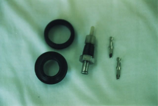
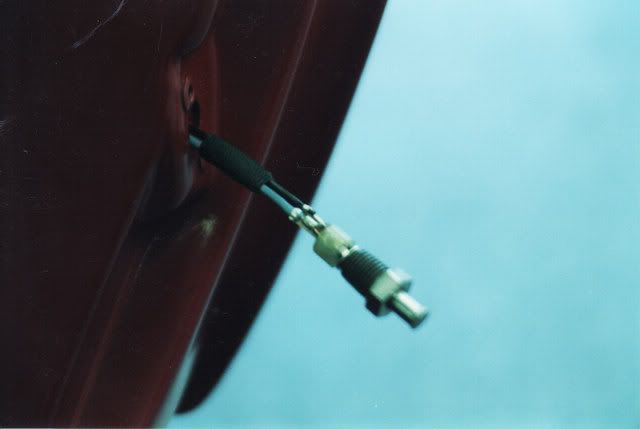
My understanding is that the connector is 'one time use' only.
The barbs on the connector catch in the 'slot' in the nylon switch body and hold the connector in place.
That's why the vendors list the cinnectors right after the switches.
Regards,
Alan
Corvette Stories
The Best of Corvette for Corvette Enthusiasts

Top 10 Most Expensive Corvettes Ever Sold on Bring A Trailer
Brett Foote
10 Things Every Corvette Owner Needs (2026 Edition)
Michael S. Palmer
8 Most "Only Corvette Owners Understand" Quirks and Problems
Pouria Savadkouei
10 Reasons the C6 Z06 is Still A Performance Benchmark After 20 Years
Joe Kucinski
How Much Horsepower Every Corvette Engine "LOST" in 1972
Joe Kucinski
Top 10 DOs and DON'Ts for Protecting Your Convertible Top!
Michael S. Palmer
Top 10 Most Explosive Corvettes Ever Made: Power-to-Weight Ratio Ranked!
Joe Kucinski
150 hp to 1,250 hp: Every Corvette Generation Compared by the Specs That Matter
Joe Kucinski
8 Coolest Corvette Pace Cars (and Replicas) of All Time
Verdad Gallardo
Le Mans Master
Joined: Jan 2007
Posts: 5,485
Likes: 7
From: Peekskill NY
Those are good pics Alan! I need to replace both of mine. Left one is MIA, the right doesn't spring out or light up the dash light if I pull it out.


Melting Slicks

Joined: Apr 2006
Posts: 2,084
Likes: 14
From: Airdrie Alberta
Hi HW,
I'd say you cut an ACCESS PANEL!!!!!
Regards,
Alan
I'd say you cut an ACCESS PANEL!!!!!
Regards,
Alan

I removed it with a heat gun when I was replacing my rocker channels and it gave me the opportunity to repair my Door ajar switches.
The metal backing was stripped and rusted so i fabricated new ones out of 10ga, drilled and tapped to allow new switches to screw in then riveted them to the body.
I went to the wreckers and found door switches of 70 & early 80's GM cars would work and made sure to retrieve some of the harness from the doner car.
Just one of those little things that are nice when they work.
Melting Slicks
Joined: Apr 2006
Posts: 2,084
Likes: 14
From: Airdrie Alberta
WOW! Did you need to replace the #3 mount with one of those steel replacement inserts?
Glenn
Glenn
 sure did...
http://forums.corvetteforum.com/c3-g...el-mayhem.html
Had so much fun I decided to help my Buddy do his 72 Coupe, new frame, C4 suspension, 383 & 5 speed pics to follow...


Melting Slicks


Joined: Feb 2001
Posts: 2,608
Likes: 3
From: TEXAS - you mean there are other states?
Rob ... I am having that same issue. I believe that the plastic on the new ones is too soft. The old original ones I have still work (the plastic anyway)...
So - how did you resolve Rob? I did bend the 'finger' out a bit, but it does not want to catch.
Alan - did your connectors protrude a bit - or just barely above beoing flush? Great pics.
So - how did you resolve Rob? I did bend the 'finger' out a bit, but it does not want to catch.
Alan - did your connectors protrude a bit - or just barely above beoing flush? Great pics.
Team Owner
Joined: Sep 2006
Posts: 31,280
Likes: 4,372
From: Westminster Maryland
Hi kb,
I really can't remember, (and can't take a look), how far the blade protruded. Doesn't it have to protrude a bit so the plunger touches it and makes the connection?
Regards,
Alan
I really can't remember, (and can't take a look), how far the blade protruded. Doesn't it have to protrude a bit so the plunger touches it and makes the connection?
Regards,
Alan
Melting Slicks
Joined: Feb 2001
Posts: 2,608
Likes: 3
From: TEXAS - you mean there are other states?
I think the connector metal (Lectric Limited) is greatly inferior to the OEM connector. As for the plastic for the switch (Corvette Central) , I feel it is also softer than the OEM switch plastic.
I think the trick is to 'pull back' the switch plunger assembly so that when you insert the connectors, you are not mashing them up against the bottom of the plunger area. That way the end of the connector protrudes a bit and seats well - rather than distorting the plastic or the prong.
I was successful at getting all 4 door switches working, but it was a hodgepodge of variables.... unfortunately. They work great now. I do have a set of metal connectors that I can solder on, and I will do that at a later date.
Oh - Alan - if you look closely at your picture that has teh complete assembly hanging out - I believe you can see that the connector does protrude a bit once properly seated.
Learning as I went, here is how mine played out:
The prongs broke off soooo easily on the first LR Door Ajar Switch, so I re-inserted with the pronges pointing outwards and once through the plastic in the switch, I slightly bent them outward. On the RR Door Ajar, with the connector prongs intact, I inserted the connectors with the 'finger' facing out. Still learning and wanting to ensure they stayed, I slightly bent them away from the center post on the switch. The RF Courtesy Switch was only one wire and it actually stayed stuck into the plastic switch. The LF Courtesy/Key Buzzer required me to bend the prongs outward a bit as before.
I also removed the #3 Body Mount cover and inspected for the seals. I also added some shrink tube around the wires. I heated so that only a small 1/2" area was shrunk around the wires. The rest of the shrink tube acted as a buffer and had airspace around the wires.
BTW - that key buzzer noise is annoying and kinda weenie/sickly sounding
 .... is that coming form the horn relay?
I think the trick is to 'pull back' the switch plunger assembly so that when you insert the connectors, you are not mashing them up against the bottom of the plunger area. That way the end of the connector protrudes a bit and seats well - rather than distorting the plastic or the prong.
I was successful at getting all 4 door switches working, but it was a hodgepodge of variables.... unfortunately. They work great now. I do have a set of metal connectors that I can solder on, and I will do that at a later date.
Oh - Alan - if you look closely at your picture that has teh complete assembly hanging out - I believe you can see that the connector does protrude a bit once properly seated.
Learning as I went, here is how mine played out:
The prongs broke off soooo easily on the first LR Door Ajar Switch, so I re-inserted with the pronges pointing outwards and once through the plastic in the switch, I slightly bent them outward. On the RR Door Ajar, with the connector prongs intact, I inserted the connectors with the 'finger' facing out. Still learning and wanting to ensure they stayed, I slightly bent them away from the center post on the switch. The RF Courtesy Switch was only one wire and it actually stayed stuck into the plastic switch. The LF Courtesy/Key Buzzer required me to bend the prongs outward a bit as before.
I also removed the #3 Body Mount cover and inspected for the seals. I also added some shrink tube around the wires. I heated so that only a small 1/2" area was shrunk around the wires. The rest of the shrink tube acted as a buffer and had airspace around the wires.
BTW - that key buzzer noise is annoying
and kinda weenie/sickly sounding.... is that coming form the horn relay?
Last edited by kaiserbud; Oct 16, 2011 at 04:06 PM.
