
Console Instrument Panel Connections on 81
 05-25-2013, 04:27 PM
#1
Melting Slicks

Thread Starter
Member Since: Jun 2005
Location: Rock Hill SC (Charlotte NC Area)
Posts: 2,363
Received 683 Likes
on
444 Posts
2022 C8 of the Year Finalist - Modified
2022 C7 of the Year Finalist - Unmodified

Here's an interesting one. Wanted to get some opinions before I "fixed" something I shouldn't putz with. 
I'm in the process of replacing the upper/lower console plates. Just got the upper console out of the car. The temp gauge has not worked since I got the car (nor the clock, for that matter). Check the pic below...I noticed that on one of the four screw connections behind the temp gauge, the nut is behind the circuit, where the other two have the circuit, then the nut. (pardon my terminology, if incorrect).
SO...could this be why that particular gauge isn't working, or is that how it is supposed to be connected?
Secondly...while I'm this far in, is there anything I could do to check why the clock doesn't work?
Pic...
Last edited by DWS44; 05-25-2013 at 11:04 PM.

 05-25-2013, 11:31 PM
#3
Racer

that's really interesting, I have never pulled my gauges out all the way, just far enough to replace bulbs when needed, from the look at Wilcox's it looks like that connection is not a active part of the board. so I don't think that is what is causing the temp gauge not to work.
http://willcoxcorvette.com/product_i...ducts_id=24485
http://willcoxcorvette.com/product_i...ducts_id=24485
05-26-2013, 12:28 AM
#4
Burning Brakes


This might help, it's got a little more information on it.
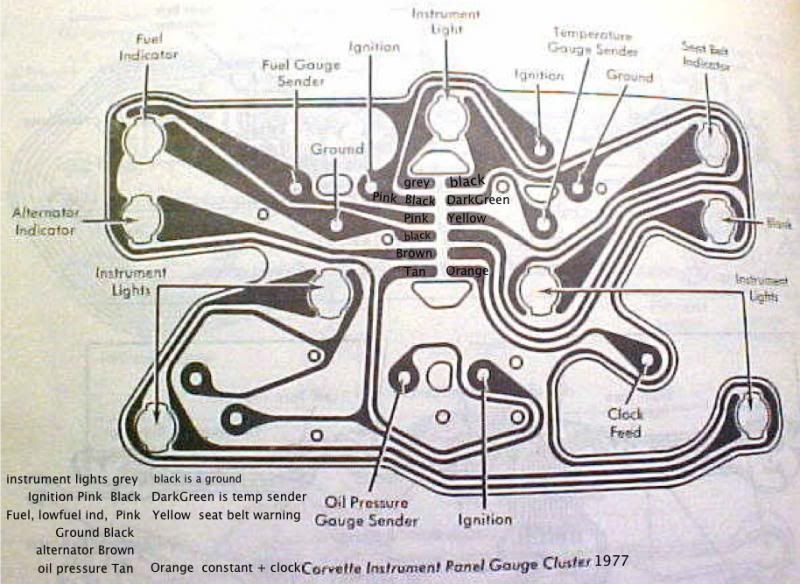
It's the same center cluster printed circuit as your 81
It looks like the top right ground is blown right where it comes out of the molex connector panel(?)
Which also connects to the seat belt light and the center right instrument panel light....so I'm guessing those lights don't work either?
It's the same center cluster printed circuit as your 81
It looks like the top right ground is blown right where it comes out of the molex connector panel(?)
Which also connects to the seat belt light and the center right instrument panel light....so I'm guessing those lights don't work either?
Last edited by TurboStitchCW; 05-26-2013 at 12:32 AM.
05-26-2013, 12:33 AM
#5
Burning Brakes
as far as the clock not working: the internal contacts may need to be cleaned (because they get a buildup of "stuff") because it looks like the circuit is still complete.
Check out this link, it helped me get my clock working and it may help you:
http://www.pcfred.com/Vettetip/FixC3Clock.htm
Check out this link, it helped me get my clock working and it may help you:
http://www.pcfred.com/Vettetip/FixC3Clock.htm
Last edited by TurboStitchCW; 05-26-2013 at 12:36 AM.
05-26-2013, 09:52 AM
#6
Melting Slicks
Thread Starter
Member Since: Jun 2005
Location: Rock Hill SC (Charlotte NC Area)
Posts: 2,363
Received 683 Likes
on
444 Posts
2022 C8 of the Year Finalist - Modified
2022 C7 of the Year Finalist - Unmodified
Thanks Turbo! That diagram is good info for sure. 
You are right about the one ground connector looking blown. I hadn't noticed that yet. One would assume that if the ground to the temp guage was blown, that could keep it from working, right? (not a lot of experience with wiring. )
)
Assuming that is blown, only real option here is to replace the printed circuit, correct? Is installing a new one really as simple as removing the individual nuts and lights, remove and replace...or is there more to it that I'm missing.
Thanks for the help, guys!
You are right about the one ground connector looking blown. I hadn't noticed that yet. One would assume that if the ground to the temp guage was blown, that could keep it from working, right? (not a lot of experience with wiring.
)Assuming that is blown, only real option here is to replace the printed circuit, correct? Is installing a new one really as simple as removing the individual nuts and lights, remove and replace...or is there more to it that I'm missing.
Thanks for the help, guys!
05-26-2013, 10:19 AM
#7
Racer
for testing purposes you could jump that burn in the ground (literally just add a wire from the good side of the ground over the burn to complete the circuit), plug in the board and see if everything comes back to life, but I would certainly replace the printed circuit, as to replacing it looks just that simple.
05-26-2013, 01:48 PM
#8

I checked photos from when I pulled my center console and panel in my '80. On my circuit board that same nut is behind the printed circuit board (and my temp gauge was/is working), so I don't think that is the problem. Usually it seems that the sender is the problem (not the gauge) when you have temp gauge issues. Search for temperature gauge threads and you'll find how to test your gauge by grounding the sender wire (very easy to do).
That one copper wire does look broken/burned. I've seen where some have laid in a jumper wire rather than replacing the whole printed circuit, but that would be up to you. The rest of the board looks better than mine did.
That one copper wire does look broken/burned. I've seen where some have laid in a jumper wire rather than replacing the whole printed circuit, but that would be up to you. The rest of the board looks better than mine did.
05-26-2013, 01:49 PM
#9
Burning Brakes
Yes, you are correct that the printed circuit is just a direct replacement. Just take out the bulbs and the nuts & capacitors (the white ceramic things), just be sure to put everything back where it came from.
The printed circuit board that chrisNY posted is the correct one, but here is a link to the same one....just with a forum discount.
http://willcoxcorvette.com/advanced_...php?cPath=2059
The printed circuit board that chrisNY posted is the correct one, but here is a link to the same one....just with a forum discount.
http://willcoxcorvette.com/advanced_...php?cPath=2059
05-27-2013, 01:09 AM
#10
Former Vendor
Member Since: Aug 2006
Location: Jeffersonville Indiana 812-288-7103
Posts: 76,656
Received 1,813 Likes
on
1,458 Posts
St. Jude Donor '08-'09-'10-'11-'12-'13-'14-'15
What is the gauge doing.. that is the key question in determining what is wrong with the gauge.

Your gauge will react the exact same way.. and the end results are the same as well.
Testing a 68-76 Temperature Gauge -or- What your non working gauge can tell you!
I'd quartz convert the clock.. easy to do and I will have a video completed on this real soon.
05-27-2013, 12:45 PM
#11
Melting Slicks
Thread Starter
Member Since: Jun 2005
Location: Rock Hill SC (Charlotte NC Area)
Posts: 2,363
Received 683 Likes
on
444 Posts
2022 C8 of the Year Finalist - Modified
2022 C7 of the Year Finalist - Unmodified
Interesting video! During the time I've had the car, it's always displayed a hair above 100*, just as your video shows starting @ ~3:14 minute mark. I notice mine looks a bit different @ the 3 o'clock position, so I'm not sure how the ground washer should be fitting into the equation. The following pic is how mine looks currently (taken from the top looking down).

As for the clock, the car already has a quartz clock in it...says "quartz" across the front at least. On the back, it has a "Westclox" chrome decal with a date stamp of 6/25/81, which jives with the build date of the car, so I assume its the original clock.
As for the clock, the car already has a quartz clock in it...says "quartz" across the front at least. On the back, it has a "Westclox" chrome decal with a date stamp of 6/25/81, which jives with the build date of the car, so I assume its the original clock.
05-27-2013, 06:57 PM
#12
Former Vendor
Member Since: Aug 2006
Location: Jeffersonville Indiana 812-288-7103
Posts: 76,656
Received 1,813 Likes
on
1,458 Posts
St. Jude Donor '08-'09-'10-'11-'12-'13-'14-'15
Ok.. interesting.. your car did not use the insulation washer, but the reading means the same thing. The 3 o'clock stud is grounded to to the case somehow.. or the gauge is defective.
I'm working this from the deep cob webs in my head so if I err.. I get a pass..
Remove the pcb.. and then the gauge. With the gauge in your hand put something on the 3'oclock and 9 o'clock studs to act as an insulator.. the put the resistor back on and tighten the nuts.
Put power and ground on the gauge like this..
Power to the 12 o'clock stud, and ground to the 9 o'clock stud.
If you do this the gauge should go below 100. (lower left in picture)
Then with the power and ground hooked up, run a jumper from the 6 o'clock stud to ground on the 9 o'clock stud. The gauge should go to hot.. as pictured below. (Upper left in picture)
If it pass's this test then the gauge is working fine... and the problem is elsewhere.

Here is how the gauge wires up..

I'm working this from the deep cob webs in my head so if I err.. I get a pass..
Remove the pcb.. and then the gauge. With the gauge in your hand put something on the 3'oclock and 9 o'clock studs to act as an insulator.. the put the resistor back on and tighten the nuts.
Put power and ground on the gauge like this..
Power to the 12 o'clock stud, and ground to the 9 o'clock stud.
If you do this the gauge should go below 100. (lower left in picture)
Then with the power and ground hooked up, run a jumper from the 6 o'clock stud to ground on the 9 o'clock stud. The gauge should go to hot.. as pictured below. (Upper left in picture)
If it pass's this test then the gauge is working fine... and the problem is elsewhere.
Here is how the gauge wires up..