


Doorgunner's '68 Convertible Project
Thread Starter
2026 Loser of the Year


Joined: Sep 2013
Posts: 36,594
Likes: 7,041
From: New Or-leens Loo-z-anna
The rear Toe didn't get completed today as p-p-planned, but most of the wheels are pointing in the correct direction now...
Driver's..........front......

Driver's.........rear........

Passenger's......front.......oooooops... ...

Passenger's rear...........

(I never thought that I would look forward to wearing-out two (fairly new) old school xxtra wide tires in order to install 255s on all four rims)
15050
Driver's..........front......
Driver's.........rear........
Passenger's......front.......oooooops... ...
Passenger's rear...........
(I never thought that I would look forward to wearing-out two (fairly new) old school xxtra wide tires in order to install 255s on all four rims)
15050
Last edited by doorgunner; May 7, 2014 at 01:52 PM.
Thread Starter
2026 Loser of the Year
Joined: Sep 2013
Posts: 36,594
Likes: 7,041
From: New Or-leens Loo-z-anna
Well.............this sucks very much...................Sorry about the lack of pics!
Photobucket deleted the first 4-5 pages of my build pics......again!
I reposted as many as I could tonight.....I'll have to repost the rest of the pics this week-end
15429
R A T S !!!!
Photobucket deleted the first 4-5 pages of my build pics......again!
I reposted as many as I could tonight.....I'll have to repost the rest of the pics this week-end
15429
R A T S !!!!
Last edited by doorgunner; May 11, 2014 at 11:50 AM.
Thread Starter
2026 Loser of the Year
Joined: Sep 2013
Posts: 36,594
Likes: 7,041
From: New Or-leens Loo-z-anna
Being a rookie I did a Search but could not find dimensions for a stock 1968 trailing arm. Does anyone have a drawing of the stock offset and angles (when looking down at the top view of the arm)?
I forgot to check the arms before rebuilding them. Now I'm having trouble getting enough Toe-OUT (it has 1/4" Toe-In now) on the DRIVER'S side arm. The T/A bushing is against the outboard side of the pocket, and I still need another .125" to be close to Toe-Tolerance.
Let me rephrase the question using a diagram of a stock C3 trailing arm.....................................

What would be the Off-set distance between the machine surface A and the parallel surface B of the arm shown above? Several responses would be appreciated to get an average distance
I
forgot to check the arms before rebuilding them. Now I'm having trouble getting enough Toe-OUT (it has 1/4" Toe-In now) on the DRIVER'S side arm. The T/A bushing is against the outboard side of the pocket, and I still need another .125" to be close to Toe-Tolerance.Let me rephrase the question using a diagram of a stock C3 trailing arm.....................................
What would be the Off-set distance between the machine surface A and the parallel surface B of the arm shown above? Several responses would be appreciated to get an average distance
Last edited by doorgunner; May 16, 2014 at 01:39 PM.
Thread Starter
2026 Loser of the Year
Joined: Sep 2013
Posts: 36,594
Likes: 7,041
From: New Or-leens Loo-z-anna
I measured.....it seems like 3" would be to the far side of the trailing arm......even at that---the arm is "arched".
EDIT: Since the pocket allows a "gap" of 3/8" per side on the trailing arm............I "straightened" the arm to approx. 2" "between the front end of the trailing arm and the machined surface.
After assembling everything and installing the wheel, the difference is very noticeable and I will now be able to set the Toe to the correct specs.
More "discoveries": Well.....what happened was....a previous owner installed 15 x 8" rims and 295 rear tires....then he decided to "arch" the trailing arms to keep the E-brake brackets on the trailing arms from rubbing on the monster tires......which threw the Toe inboard 1/4" on each tire! I straightened the trailing arm and removed the e-brake bracket for re-location later...I will re-shim the Toe and reset the Camber on the driver trailing arm tomorrow----then tackle the passenger trailing arm now that I have a clue as to what has been "done".
(I down to 30 minute to completely remove a trailing arm now......LOL)
Thanks very much for getting me out of a rookie-jam.
Last edited by doorgunner; May 16, 2014 at 02:02 AM.
Thread Starter
2026 Loser of the Year
Joined: Sep 2013
Posts: 36,594
Likes: 7,041
From: New Or-leens Loo-z-anna


At least they left the original bonding strip/"flange" under the deck when they "modified the tailight clip"!
Last edited by doorgunner; May 16, 2014 at 02:05 AM.
Corvette Stories
The Best of Corvette for Corvette Enthusiasts

Top 10 Most Expensive Corvettes Ever Sold on Bring A Trailer
Brett Foote
10 Things Every Corvette Owner Needs (2026 Edition)
Michael S. Palmer
8 Most "Only Corvette Owners Understand" Quirks and Problems
Pouria Savadkouei
10 Reasons the C6 Z06 is Still A Performance Benchmark After 20 Years
Joe Kucinski
How Much Horsepower Every Corvette Engine "LOST" in 1972
Joe Kucinski
Top 10 DOs and DON'Ts for Protecting Your Convertible Top!
Michael S. Palmer
Top 10 Most Explosive Corvettes Ever Made: Power-to-Weight Ratio Ranked!
Joe Kucinski
150 hp to 1,250 hp: Every Corvette Generation Compared by the Specs That Matter
Joe Kucinski
8 Coolest Corvette Pace Cars (and Replicas) of All Time
Verdad Gallardo
Thread Starter
2026 Loser of the Year
Joined: Sep 2013
Posts: 36,594
Likes: 7,041
From: New Or-leens Loo-z-anna
r......................if the PTSD hadn't been hammering me so much, it would already be installed......but right now I'm about 4 months behind schedule--total.
Working out the trailing arm previous-owner "modification" will add another week to the alignment process....since I have to cut 1 & 1/2 "wraps" off each coil spring to get the correct front fender-lip height/re-shim contol arms----I may as well remove /rebush/clean/paint them and the coil springs which are fairly "crusty"!
I really want to get it mechanically safe and finish the interior (seats)......then put some local miles on it---bad paint and all

EDIT/Moved from Tech Forum:
I do not mean to throw sticks in the spokes...but there are 2 issues I would like to give a comment on FROM EXPERIENCE.
In the photo's the urethane bushing appear to be Vette Brakes and Products trailing arm bushings. Although these bushings can be installed at a persons home with no really specific tools to stake them...there is a slight design flaw with them. And the flaw is that they are wider than original bushings...so when they get installed...there is a chance that the trailing arm may need to be removed and "tweaked" due to the area needed for an alignment has been reduced...and the trailing arm had an issue that is now identifiable ...but with the original bushings...it could be aligned. I am just saying that this has bit me more than one time and I do not use these bushing any longer...I use other urethane bushings that are just like the rubber style when installed.
The other issue is that using this measuring method is good for a basic idea...but often times the problem that I have run into is that the flat surface where the bearing housing seats against the trailing arm gets tweaked and it can be identified on how well centered the outer bearing/U-joint flange is attached to the spindle in relation to the large hole that is in the trailing arm where the bearing/U-joint flange spins. You would think that it is strong at this mounting area...but do not be fooled. Just saying.
DUB
I know exactly what you are referring to (only because I've been "hugging" that trailing arm assembly for two days)......I'm going to the garage now and check overall width of the bushing.
I did pay close attention to the machined-flat area that the hub bolts to---it was in good shape.
But I will measure the hole-to-flange clearance just to be sure.
Thanks for letting me know what to look for so I won't have to remove the trailing arm a third time....but I am getting faster at it......LOL!
Last edited by doorgunner; May 16, 2014 at 11:55 PM.
Thread Starter
2026 Loser of the Year
Joined: Sep 2013
Posts: 36,594
Likes: 7,041
From: New Or-leens Loo-z-anna
I do not mean to throw sticks in the spokes...but there are 2 issues I would like to give a comment on FROM EXPERIENCE.
In the photo's the urethane bushing appear to be Vette Brakes and Products trailing arm bushings. Although these bushings can be installed at a persons home with no really specific tools to stake them...there is a slight design flaw with them. And the flaw is that they are wider than original bushings...so when they get installed...there is a chance that the trailing arm may need to be removed and "tweaked" due to the area needed for an alignment has been reduced...and the trailing arm had an issue that is now identifiable ...but with the original bushings...it could be aligned. I am just saying that this has bit me more than one time and I do not use these bushing any longer...I use other urethane bushings that are just like the rubber style when installed. The previous owner installed rubber bushings that are approx. 2 1/4" over all width.
The other issue is that using this measuring method is good for a basic idea...but often times the problem that I have run into is that the flat surface where the bearing housing seats against the trailing arm gets tweaked and it can be identified on how well centered the outer bearing/U-joint flange is attached to the spindle in relation to the large hole that is in the trailing arm where the bearing/U-joint flange spins. You would think that it is strong at this mounting area...but do not be fooled. Just saying. I found 1/16" difference at the four flange shoulders to the hole lip.
DUB
It now has 0 degrees Toe......and 1/8" positive Camber. That's close enough for 10pm tonight.
I'll fine tune it tomorrow and install cotter pins to hold the shims in place.........WHEW!
15830
Last edited by doorgunner; May 17, 2014 at 05:23 PM.
Thread Starter
2026 Loser of the Year
Joined: Sep 2013
Posts: 36,594
Likes: 7,041
From: New Or-leens Loo-z-anna
I think 4" of clearance above the front tire is a LITTLE too much........

So the spring, which the end of the upper and lower coils were NOT against the stops, is removed and a full coil is cut off to start with.....

Now we all know that springs look great cleaned and painted......

However....lower control arms do not look great next to painted springs, so........control arm MUST come out for cleaning and painting...............

Ball joints do not look nice with 1/4 pound of grease on them so.......

I may as well touch this up while the A.D.D. is turned on......

Well.......I'm off......to get a Sonic meal deal and a few spraycans of paint.
(Which means a fast trip to the auto store for new bushings)
15905
So the spring, which the end of the upper and lower coils were NOT against the stops, is removed and a full coil is cut off to start with.....
Now we all know that springs look great cleaned and painted......
However....lower control arms do not look great next to painted springs, so........control arm MUST come out for cleaning and painting...............
Ball joints do not look nice with 1/4 pound of grease on them so.......
I may as well touch this up while the A.D.D. is turned on......
Well.......I'm off......to get a Sonic meal deal and a few spraycans of paint.
(Which means a fast trip to the auto store for new bushings)
15905
Last edited by doorgunner; May 17, 2014 at 08:05 PM.
Thread Starter
2026 Loser of the Year
Joined: Sep 2013
Posts: 36,594
Likes: 7,041
From: New Or-leens Loo-z-anna
Thanks for the shortcut.....I've never changed seized/rusted/frozen/rusted control arm bushings so fast in my life!
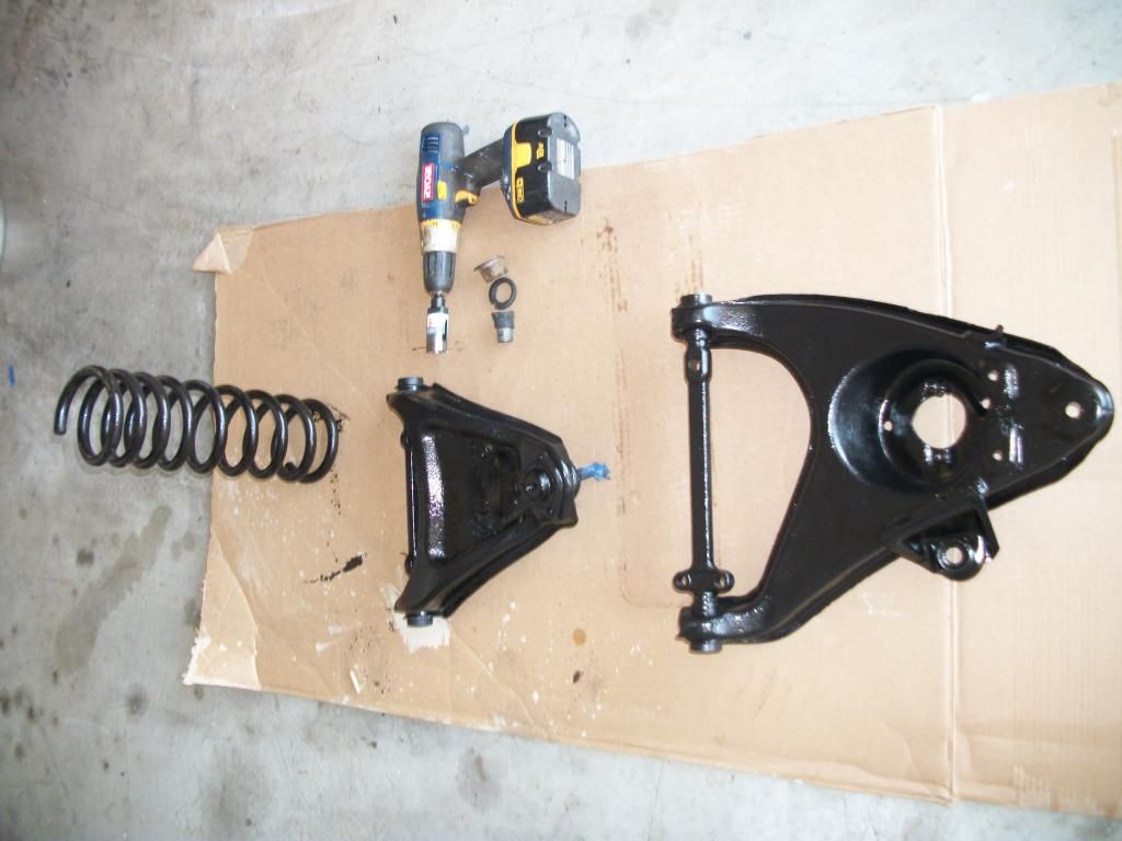
The 1 1/8" diameter extra-long hole saw idea was great....I removed the bushings/cleaned the control arms/installed new bushings/painted both control arms.........
in the same time it normally takes me to remove TWO bushhings with a propane torch/many chisels/a LARGE hammer/two vices {normally I destroy one in the process}!
Here ya' go......................................

I sprayed them with gloss black/in Loo-z-anna, we get so much rain--they will look satin black in a week!
Thanks again for answering rookie's questions a thousand times and providing great advice........
I just may get this thing done!
16090
The 1 1/8" diameter extra-long hole saw idea was great....I removed the bushings/cleaned the control arms/installed new bushings/painted both control arms.........
in the same time it normally takes me to remove TWO bushhings with a propane torch/many chisels/a LARGE hammer/two vices {normally I destroy one in the process}!
Here ya' go......................................
I sprayed them with gloss black/in Loo-z-anna, we get so much rain--they will look satin black in a week!
Thanks again for answering rookie's questions a thousand times and providing great advice........
I just may get this thing done!
16090
Last edited by doorgunner; May 22, 2014 at 01:16 AM.


 )
)
Pro

Joined: Feb 2014
Posts: 692
Likes: 2
From: Seguin TX
Thanks for the shortcut.....I've never changed seized/rusted/frozen/rusted control arm bushings so fast in my life!
The 1 1/8" diameter extra-long hole saw idea was great....I removed the bushings/cleaned the control arms/installed new bushings/painted both control arms.........
in the same time it normally takes me to remove TWO bushhings with a propane torch/many chisels/a LARGE hammer/two vices {normally I destroy one in the process}!
Here ya' go......................................
I spayed them with gloss black/in Loo-z-anna, we get so much rain--they will look satin black in a week!
Thanks again for answering rookie's questions a thousand times and providing great advice........
I just may get this thing done!
16090
Thread Starter
2026 Loser of the Year
Joined: Sep 2013
Posts: 36,594
Likes: 7,041
From: New Or-leens Loo-z-anna
I ...........uhhhhhhhhh......still have to rebush the passenger-side front wheel.....
then I need to see if the passenger-side trailing arm needs to be "straightened"........
good thing you guys already provided the dimension for the bushing-to-hub flange offset.
None of the above will be a problem.....now that I am an experienced
R O O K I E !!!!!
Thread Starter
2026 Loser of the Year
Joined: Sep 2013
Posts: 36,594
Likes: 7,041
From: New Or-leens Loo-z-anna
Copied from a TECH Forum thread: Cutting a coil spring to lower front of car
O.K.
I'm a Rookie......bear with me....the front fender lip height was 29" to start with.......4" above the tire!
USE JACKSTANDS/BE CAREFUL/SPRINGS BITE!
I found from forum members that leaving the wheel on the car makes it easier (which doesn't sound right...LOL)........ I jacked the car....jackstand under frame......jacked lower control arm.....removed the shock......removed nut & loosened tierod with pickle fork......lowered control arm....pulled wheel away a feel inches.....loosened end caps on lower control arm shaft to allow control arm to settle to floor....pried spring out of lower arm and removed from chassis...

Here is a pick looking up into the spring pocket....notice to the left/inside edge of the top coil.....is a 3/8" hole I drilled with a 1& 1/4" long bolt inserted into the hole to hold the top of the spring in the pocket when re-installing the spring......this bolt keeps the upper portion of the spring from binding/refusing to stay in the spring pocket depression...

The lower part of the spring is removed with a prybar ( FIRST...remove the rubber bump-stop to keep from damaging it)......Here is a pic of the " upper spring alignment bolt that I installed....

Here's a pic of the 1st and 2nd cut and changes that the cuts made/the measurements aren't exact...the modified coil spring is now approx. 14" long......

Here's a measurement after the spring is re-in stalled and the car is driven to settle the suspension.....

I'll post more pics after I remove the passenger's spring and modify it (I hope all of the above makes some sense, since I did not do a step-by-step explanation--assuming that members have read threads about the topic).
Thanks to Forum members for all the short cuts/thread-how-to's!
16300
O.K.
I'm a Rookie......bear with me....the front fender lip height was 29" to start with.......4" above the tire!
USE JACKSTANDS/BE CAREFUL/SPRINGS BITE!
I found from forum members that leaving the wheel on the car makes it easier (which doesn't sound right...LOL)........ I jacked the car....jackstand under frame......jacked lower control arm.....removed the shock......removed nut & loosened tierod with pickle fork......lowered control arm....pulled wheel away a feel inches.....loosened end caps on lower control arm shaft to allow control arm to settle to floor....pried spring out of lower arm and removed from chassis...
Here is a pick looking up into the spring pocket....notice to the left/inside edge of the top coil.....is a 3/8" hole I drilled with a 1& 1/4" long bolt inserted into the hole to hold the top of the spring in the pocket when re-installing the spring......this bolt keeps the upper portion of the spring from binding/refusing to stay in the spring pocket depression...
The lower part of the spring is removed with a prybar ( FIRST...remove the rubber bump-stop to keep from damaging it)......Here is a pic of the " upper spring alignment bolt that I installed....
Here's a pic of the 1st and 2nd cut and changes that the cuts made/the measurements aren't exact...the modified coil spring is now approx. 14" long......
Here's a measurement after the spring is re-in stalled and the car is driven to settle the suspension.....
I'll post more pics after I remove the passenger's spring and modify it (I hope all of the above makes some sense, since I did not do a step-by-step explanation--assuming that members have read threads about the topic).
Thanks to Forum members for all the short cuts/thread-how-to's!
16300
Last edited by doorgunner; May 24, 2014 at 11:34 PM.
Thread Starter
2026 Loser of the Year
Joined: Sep 2013
Posts: 36,594
Likes: 7,041
From: New Or-leens Loo-z-anna
Modifying the passenger's side suspension:
Here's the front view of the.....................'68/'78..............project. It was nice of Bubba to leave the '68 turn signals tie-wrapped into the rectangular '78 grill openings......

The lower ball joint is separated and the wheel/spindle assembly is moved out of the way........the spring has been removed, cut to length, cleaned, painted and ready to be installed

The control arm bushings were falling apart so I removed them and cleaned up the bushing holes in the control arm......

I'll remove the upper control arm tomorrow and clean/repaint/rebush them.
16390
Here's the front view of the.....................'68/'78..............project. It was nice of Bubba to leave the '68 turn signals tie-wrapped into the rectangular '78 grill openings......
The lower ball joint is separated and the wheel/spindle assembly is moved out of the way........the spring has been removed, cut to length, cleaned, painted and ready to be installed
The control arm bushings were falling apart so I removed them and cleaned up the bushing holes in the control arm......
I'll remove the upper control arm tomorrow and clean/repaint/rebush them.
16390
Last edited by doorgunner; May 24, 2014 at 11:50 PM.

Safety Car


Joined: Jun 2013
Posts: 4,399
Likes: 793
I took your advice and went to Harbor Freight and picked up that blaster you showed me. Also got a piece of better hose. Got a free box of coarse ground walnut shells. This thing is great man, and does save allot of time. Great rookie advice thanks
R
R
Safety Car
Joined: Jun 2013
Posts: 4,399
Likes: 793
 I took your advice and went to Harbor Freight and picked up that blaster you showed me. Also got a piece of better hose. Got a free box of coarse ground walnut shells. This thing is great man, and does save allot of time. Great rookie advice thanks.
R