When you click on links to various merchants on this site and make a purchase, this can result in this site earning a commission. Affiliate programs and affiliations include, but are not limited to, the eBay Partner Network.
Hi RR,
Merry Christmas!
The Astro Ventilation system was designed to take the place of the vent windows which Corvettes had through the 1967 model year.
68 cars have the Astro Ventilation system.
I BELIEVE in 68 the system consisted of the 2 grills in the rear deck, a fiberglass plenum under each grill and a rubber 'flap' that helped regulate the flow of interior air. The system was found to be too rudimentary to have the effect the designers hoped for.
The system was changed slightly in 69 when vacuum operated sheet metal doors were added that opened when the temperature wheel on the console heater/defroster control was turned to 'C', which allowed air flow through the interior, and closed the doors when the wheel was turned to 'H' which allowed the heater to warm the air in the interior.
On coupes the doors are on the underside of the rear deck just behind and below the rear window. On convertibles the doors are on the upper portion of the rear bulkhead.
I remember seeing a picture of a 68 system fairly recently… hopefully it'll pop up again.
Regards,
Alan
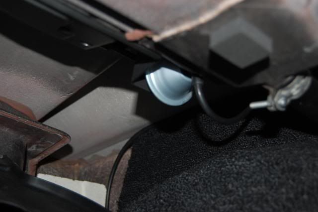
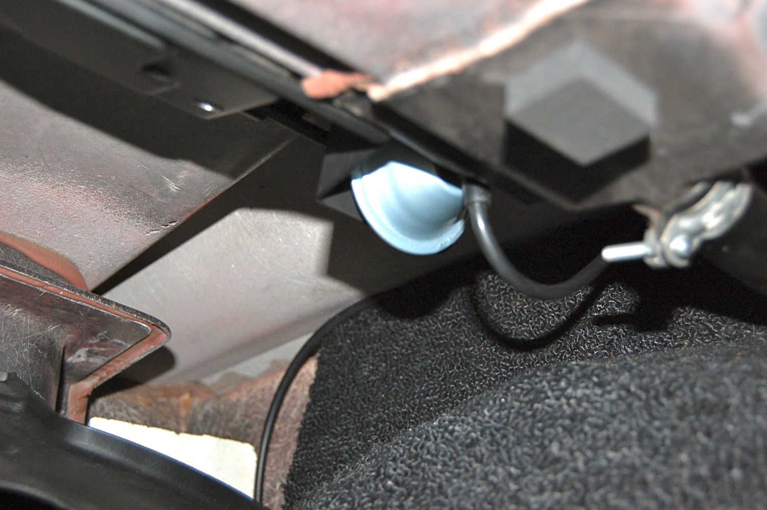
Here's the vacuum supply hose, actuator, and a small part of one of the doors (to the left of the actuator) from a 71.
2020 Corvette of the Year Finalist (performance mods)
2019 C3 of Year Winner (performance mods)
2016 C3 of Year Finalist
Thanks Alan. I saw the vents in the back of the convertible top compartment. I'm missing the screen and flap on one. Ill have to look at the vendors sites.
Thanks. Merry Christmas
Thanks Alan. I saw the vents in the back of the convertible top compartment. I'm missing the screen and flap on one. Ill have to look at the vendors sites.
Thanks. Merry Christmas
RR
In 68 the rear Astro Ventilation vent was just a rubber flap attached to a metal frame.
I'm not sure how the assembly line guys thought they were supposed to work, but on my car (convertible, no A/C) they were purposely glued shut.
Hi John,
Merry Christmas!
I think the designers must have thought that the 'high pressure' created in the interior, when the kick panel vents an/or astro vents were open, would push the 'flap' open a bit and some air would flow out.
???
Regards,
Alan
I'd like to save those pictures if it's o.k. with you.
Alan
In theory they had a good idea, but this picture shows the glue the assembly people used in the corners on my car to make the flaps inoperable. No amount of pressure differential is going to work on my car. Why they did this I have no idea, it is not what the designers originally had in mind.
I have no problems if you save and reuse the pictures.
WOW! I never even heard of this or knew it existed! Glad you asked about that RR! Something else to be on the look out for when I get to that point and add to my to do list! Great learning things on the forum! Thanks guys!
Could be a previous owner glued your flaps shut? May have been a water intrusion issue, or leaves/debris getting into the plenum?
My question, on my '69, is how to hook up the vacuum hose to the actuator of the doors? My hose was cut about 2 feet rearward of the control head on the console. So I need to route a new hose to the rear actuator and not sure which of the 2 nipples to connect it to.
My doors do seem to be in a normally-open position, and can be forced closed with some hand force against the actuator, but the actuator pushes them open again. But there is no vacuum line hooked up yet.
Hi Bb,
When the heater/defroster controller right wheel is on H the doors are shut, moving the wheel to C opens the doors.
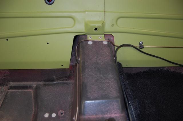
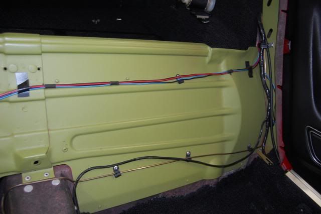
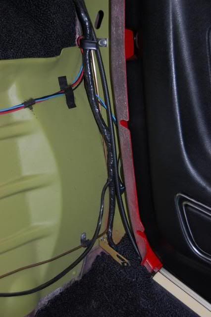
Originally the vacuum line consisted of a short piece of vacuum hose at the heater/defroster controller connection in the console, then a long piece of thin copper tubing that ran back along the transmission tunnel, across the seat bulkhead, and up the lock pillar where it changed back to a piece of rubber tubing that connected to the vacuum pot on the astro door mechanism.
Regards,
Alan
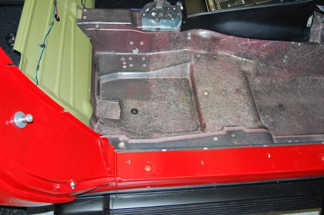
Copper tube on side of transmission tunnel.
The copper tube on the transmission tunnel and seat bulkhead.
Interesting enough, I have a 68 BB w/ factory installed AC and the rear deck vents are just cosmetic.
I cleaned out the leaves and made sure the wells were clean and it drains now out the wheel wells.
My point is they really had some mods to do on the assembly line when a car came down the line with AC listed on the build sheet.
Thank you for the educational thread.
Marshal
Thanks Alan- Once again, pristine photos of a pristine vehicle! I wonder if everything in your life is as meticulous as your Vette?
Looks like the copper tubing is missing from mine, as all I have is the front length of the rubber hose from the R/S control wheel hook-up. I'll try to re-route something over the weekend (wondering if just one continuous rubber hose would suffice, or if the tubing was meant to prevent pinching by the seat, etc.)
And once I get back to the rear actuator, I'll experiment with which nipple to connect to based on functioning the control wheel up front.
My 69 with AC doesnt have all these flaps that I know of. I thought I heard that factory ac cars did not come with the entire system setup for the ventilation, is that correct?
Hi x,
Cars with a/c did not have an operating Astro-Vent system.
They still had the 2 grills in the rear deck and the fiberglass plenum below them.
But, instead of the 'flapper doors', a black metal cover plate was screwed in place on the plenums.
Regards,
Alan
My 69 with AC doesnt have all these flaps that I know of. I thought I heard that factory ac cars did not come with the entire system setup for the ventilation, is that correct?
That is correct no vents in the rear deck.
Marshal
Hi Marshall,
Maybe I'm not understanding what you posted.
I believe all cars had the grills in the rear deck.
I don't think there were 2 molds, one for non a/c decks and one for a/c decks.
Regards,
Alan
I believe on a/c convertibles because of the location of the vents on the deck (further back than on coupes) you can look through the grills and see the ground.
Thanks Again Alan!
Do you have any detailed photos of the junction points?
Interested in how the front hose from the control head, interfaces to the copper tube, and then again to the rear segment of rubber hose.
And then how that rear hose routes to the vacuum pot.
I've got a small section of the front hose with me to take to the store, but it seems quite small in I.D. (maybe 1/8") for fitting a very tiny copper tube into - with a hose clamp (?).
I'd like to get this line re-constructed properly while the consoles are currently out.
Would it be sufficient to just run hose all the way back to the pot?
Last edited by Bergerboy; Oct 27, 2016 at 08:29 AM.
Hi Bb,
The connection at the heater/defroster is a special connector that's has the 2 hoses molded to it.
One is the vacuum supply to that side of the controller.. H or C, and the other is a length of tubing about 1 foot long that runs to the copper tube.
The connection at the astro doors is a piece of rubber tubing about 18" long. It has a special connector at the end that connects to the vacuum pot. A regular piece of vacuum tubing will work at this location.
Regards,
Alan
Do you have close-up pix of the junctions where the hose fits with the copper tubing?
Is there a clamp? Or just a press-in fit? I assume the Tubing fits inside the ID of the hose, but it is quite small.
And what about the special connector you mentioned that goes to the actuator?
These details are not shown in the AIM that I can find.
Also - please clarify if you think a full-length of rubber hose should be sufficient from the control all the way back to the actuator. Or if there is enough of a risk of pinching along that length to warrant the copper tubing.
Thanks (as always!)
Designer Imagines A Corvette That Looks More Like a Corvette Than the Corvette
Slideshow: A Jaguar designer's personal project imagines what a modern front-engined Corvette might look like if Chevrolet revisited the golden age of the Stingray.