When you click on links to various merchants on this site and make a purchase, this can result in this site earning a commission. Affiliate programs and affiliations include, but are not limited to, the eBay Partner Network.
That schematic must be from something newer.
On my poor old car the window motors have two sets of windings with the case ground where that one reverses the two contacts for up/down. The paddle switched just take the positive from the PW relay and direct it to one of the two windings.
I'll post the schematic I came up with JIC someone down the road wants it.
M
Please post up this schematic! It would be tremendously helpful!!!
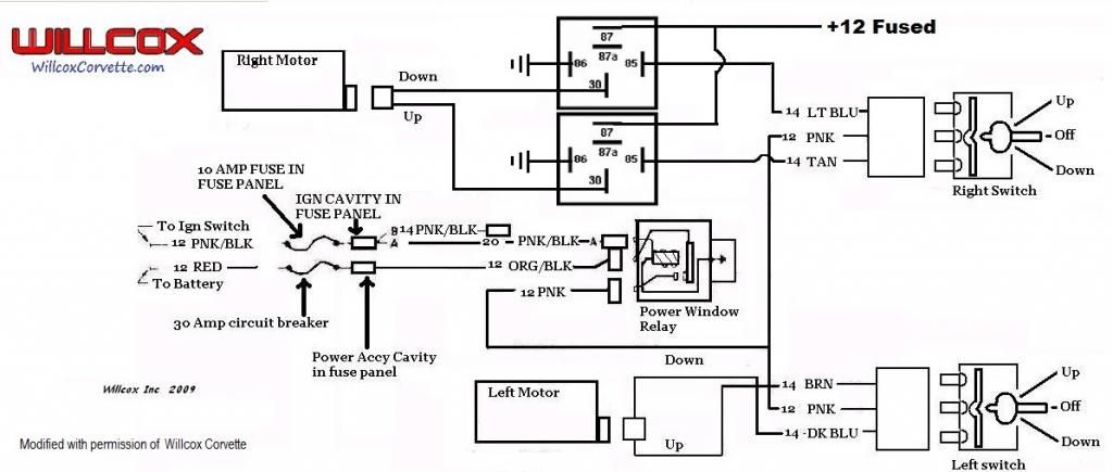
Here's a diagram I used w/ perrmission from Willcox-
Factory wire colors- added relays on the right side- and stock on the left side. Not familiar w/ Mooser's switches (Speedway Motors?)- but sounds as though they are SPDT- AKA single pole double throw.
I used Jaguar switches in mine- so I didn't want to flow any current through them!!!
My console is not stock- so I mounter the relays to the trans tunnel- also have a timer circuit on them- so when I shut the car off- I have about 3 minutes to still use the windows.
Hey Richard! Glad you chimed in.
Mooser is using Autoloc switches, and they are SPDT, I believe (which are required for stock motors).
My issue with your schematic is that my car did NOT have PW originally, so I am missing some key parts (circuit breaker & Original relay system. I cant yet figure out how Mooser did both switches with the 2 relays. I obviously have the IGN &ACCY Cavity in my fuse panel.
If you look closely at the pic- he's running 4 relays- they are just stacked on top of each other.
You don't need tio copy the factory then-
Just hit a good power source- the battery is right there- fuse at the battery- or use a 30A circuit breaker - less then $10. And use an ignition source the power the relays- then the ground wires will run to the switches and control up and down. That way- a small amount of current (less than �A) will be needed from the ignition source- and the big power comes directly from the battery. And the LED illumination- can be powered by the dash lights.
Just email me- I've got a diagram on my home computer-
I'm actually running spst (momentary) switches, the reason you see the 4 wires on each push button is because they have the LED halo as well.
Since they were separate momentary switches I had to wire them slightly different that what Willcoxs diagram is. I'll scan something up here in a bit for future reference but if your using newer motors, go with what RBrid shows, if your doing older motors with paddle switches, use the Willcox willcox/richard diagram.
If you look closely at the pic- he's running 4 relays- they are just stacked on top of each other.
You don't need tio copy the factory then-
Just hit a good power source- the battery is right there- fuse at the battery- or use a 30A circuit breaker - less then $10. And use an ignition source the power the relays- then the ground wires will run to the switches and control up and down. That way- a small amount of current (less than �A) will be needed from the ignition source- and the big power comes directly from the battery. And the LED illumination- can be powered by the dash lights.
Just email me- I've got a diagram on my home computer-
richard454 at comcast dot net
Richard - Good eye. Didn't see the 4 relays! That helps me understand much better. Will shoot you an email. Thanks!
I'm actually running spst (momentary) switches, the reason you see the 4 wires on each push button is because they have the LED halo as well.
Since they were separate momentary switches I had to wire them slightly different that what Willcoxs diagram is. I'll scan something up here in a bit for future reference but if your using newer motors, go with what RBrid shows, if your doing older motors with paddle switches, use the Willcox willcox/richard diagram.
M
Mooser - Those Autoloc switches drew me to your post. My plan is to use the same switches in a custom bezel on the center console below the shifter.
I love your custom button carriers, but lack the access to the equipment
Looking forward to seeing your schematic for how you wired them.
For what it's worth, here's basically how mine are wired
The power feeding each push button goes through the normally closed contact (30 to & 87A) on the opposite direction relay. That way, when either button is pressed, it will cut the power that goes to the other button and prevents it from being able to energize both the up and down windings of the motor at the same time.
That main positive feed goes into both relays (term#30) and mine came from the original power window relay, circuit breaker etc.
This is of course for the window motors that have a case ground and separate up/down windings rather than the newer(?) style that you just reverse the + and - on the motor to change directions
I forgot the LED's. I wired a single resistor inline with the power going to the common LED +. I'll have to check now, I think it ended up as a 330ohm (or that might have been calc min and I ended up using a 1kto bring the brightness down to resonable I forget, have to check the notes I made in the wiring diagrams)
M
For what it's worth, here's basically how mine are wired
The power feeding each push button goes through the normally closed contact (30 to & 87A) on the opposite direction relay. That way, when either button is pressed, it will cut the power that goes to the other button and prevents it from being able to energize both the up and down windings of the motor at the same time.
That main positive feed goes into both relays (term#30) and mine came from the original power window relay, circuit breaker etc.
This is of course for the window motors that have a case ground and separate up/down windings rather than the newer(?) style that you just reverse the + and - on the motor to change directions
M
Perfect! My motors are the original case grounded type. This will help me tremendously!
I originally wired the LED halos up so they turned on when you pressed the button... Then realized that your finger covered the entire button when you pressed it and you couldn't see the halo So I changed it work with the dash lights
I thought about getting another e-brake cover for a non-PW car and drilling it for the larger switches but thought they were just too big and leaned towards gaudy somewhat
M


 The double SPST Autolocs SHOULD be wired like that w/ the two winding motors.
 So I changed it work with the dash lights