


C3 frame torsion testing
Thread Starter
Tech Contributor


Joined: Jun 2004
Posts: 20,936
Likes: 962
From: I tend to be leery of any guy who doesn't own a chainsaw or a handgun.
69427 Nice job of performing some interesting research. Your torsion tube idea is analogous to the effect of an "anti-sway" bar. You are absolutely correct. The d^4 part of the swaybar formula is what helped me decide the size of the tube. I think it would also transfer more torque to the wheels as well. Relative to the description of torsion resistance in your wooden model, do you have an idea about how much the torsion tube stiffened the frame? I did several iterations of modifications to the model, and posted them on another forum after several of the CF members got fed up with some of the silliness (that still is on display here) and moved to a different forum. The torsion tube consistently increased the torsional rigidity of the model. The limitation was that it was only able to stiffen up approximately 40% of the wheelbase. I would have liked to run this tube through the whole wheelbase, but unfortunately the engine/transmission location takes first priority for much of the forward area of the wheelbase.  For example, 1" less deflection with 1000# asymmetric loading, etc. We're on the same wavelength here. It's my plan to run tests with and without the tube to determine the contribution of the tube. An idea for you: Some racing organizations require that safety hoops be installed to restrain a "flailing" drive shaft. Your torsion tube around the drive shaft would accomplish two functions. You would probably need to have the torsion tube attached to ladder components that could be unbolted for servicing the u-joints.
For example, 1" less deflection with 1000# asymmetric loading, etc. We're on the same wavelength here. It's my plan to run tests with and without the tube to determine the contribution of the tube. An idea for you: Some racing organizations require that safety hoops be installed to restrain a "flailing" drive shaft. Your torsion tube around the drive shaft would accomplish two functions. You would probably need to have the torsion tube attached to ladder components that could be unbolted for servicing the u-joints.
Melting Slicks


Joined: Mar 2008
Posts: 2,989
Likes: 198
From: Meriden CT
What part of "Please take your silliness elsewhere" was I unclear about? I can certainly rephrase it if that would help.
Regarding the engineering and physics reasons for these changes, I have spoken to several very experienced fabricators and engineers on other forums, and have listened to their learned opinions. Regarding you, I have yet to hear or see evidence of what your schooling or technical expertise is. I do not consider the gift of sarcasm as a useful tool in chassis tuning.
And, unless that's your grandmother's car in your avatar, the suspension that has been fitted to this frame is decades more modern than yours.
Now, once again, please go away.
I think this thread is very interesting and I will not go away. Now post some more clear pictures so we can continue.

Burning Brakes

Joined: Feb 2000
Posts: 1,246
Likes: 1
I have to agree with the statement that the rear bar does little, if you want to stiffen up the weak part there (which is the welded kickup part) you have to add a gusset or a brace that spans this area, not one that starts from it to another point. A gusset on the front of the kickup or 2 the sides of the kickup aiming forward would have done that. The only issue is that the body won't fit when you do that.
The tubes inside the frame will add to torsional rigidity, just like a X member used on C4s does, and the torque tube will help too. A rollcage is much more effective because you're adding height to the structure but I applaud the man for thinking outside the box and not welding a cage in his car.
SH-60B, if you're so smart on the subject, why not come with some workable solutions other than suggesting a cage, which it's clear the man does not want.
Last edited by V-Twin; Sep 29, 2008 at 10:31 AM.
Thread Starter
Tech Contributor
Joined: Jun 2004
Posts: 20,936
Likes: 962
From: I tend to be leery of any guy who doesn't own a chainsaw or a handgun.
I have years of fabrication experience,more than you could possibly aquire on your own unless it was your job, with paid training prior to that. My resume' and my grandmother are not the issues here. You can't post something anywhere as odd as that frame work and not expect some criticism. Learn from it and move ahead.
I think this thread is very interesting and I will not go away. Now post some more clear pictures so we can continue.
I think this thread is very interesting and I will not go away. Now post some more clear pictures so we can continue.
1) Examples of your fabricating capability.
2) Close up photos of your car showing me what mods you have made to it. The choice of vehicle mods tells a lot about one's understanding of vehicle dynamics.
So far, you've shown me little to make me take you seriously as an automotive expert, or even a serious critic. Perhaps you'll show me something of substance, and I'll then be able to take your questions and comments seriously. (And I'm quite sincere in this request for evidence. I enjoy in-depth technical discussions with learned individuals, and the exchange of knowledge. But I find it an unproductive use of my time dealing with people who offer up sarcasm rather than technical information.)
Racer

Joined: Dec 2004
Posts: 410
Likes: 0
From: Wichita Kansas
I find your reseach interesting. I've always AutoX my car with the T tops out and ran it this year a couple of times with them in. The added rigidity slowed me down, about 1 second on a50 sec course, as my suspension is set for all the flex. I could set it for tops in but I like the wind in my face and the added head room with helmet.

Racer
Joined: Oct 2006
Posts: 435
Likes: 18
From: Florida
Doesnt someone make a foam you can spray into your frame that stiffens it up, something like what the ford trucks get? I also remember seeing a bar bolted/welded into a honda that went across the backseat foot area that was suppose to tighten the frame up alot.....

Racer
Joined: Mar 2004
Posts: 292
Likes: 2
From: Plumas Lake CA
I'm no fabricator, but it seems a sturdy hinge/door bar/latch mechanism (hidden within the door and replacing the existing hinge/latch assembly)could tie a reinforced firewall and a short "rollbar" - in the general shape and location of the "Shark Bar" - together and create lots of torsional rigidity. Add a couple of forward bars off the reinforced firewall to the front of the frame and a couple of bars rearward, off the short "rollbar" and I think you'd have a significant improvement. It would all be contingent upon how sturdy the door bar could be made.
I like the torque tube, but could you build something to resist torque around the driveshaft/tranny tunnel, sort of a giant torque tube? I think it could be made to resist more torsional force.
I really like your idea of creating a more rigid chassis without disturbing the lines or function of the existing platform.
Thread Starter
Tech Contributor
Joined: Jun 2004
Posts: 20,936
Likes: 962
From: I tend to be leery of any guy who doesn't own a chainsaw or a handgun.
I agree with your thinking here. I kicked around making some sort of backbone/birdcage (in the Maserati mode) in the tunnel area. This would make a fairly large diameter structure that would have some high torsional resistance and stiffness. Engineering-wise, I like this idea. Unfortunately, the five speed box I've got (Doug Nash 4+1) barely fits in the tunnel the way it is, and this just puts the kaibosh on that possbility. If I had the room, I'd go with that in a heartbeat.
Corvette Stories
The Best of Corvette for Corvette Enthusiasts

Every 2027 Corvette Engine Explained
Joe Kucinski
Designer Imagines A Corvette That Looks More Like a Corvette Than the Corvette
Verdad Gallardo
10 Ugly Corvettes That We Still Kinda Love
Joe Kucinski
Top 10 Most Expensive Corvettes Ever Sold on Bring A Trailer
Brett Foote
10 Things Every Corvette Owner Needs (2026 Edition)
Michael S. Palmer
8 Most "Only Corvette Owners Understand" Quirks and Problems
Pouria Savadkouei
10 Reasons the C6 Z06 is Still A Performance Benchmark After 20 Years
Joe Kucinski
How Much Horsepower Every Corvette Engine "LOST" in 1972
Joe Kucinski
Top 10 DOs and DON'Ts for Protecting Your Convertible Top!
Michael S. Palmer
Thread Starter
Tech Contributor
Joined: Jun 2004
Posts: 20,936
Likes: 962
From: I tend to be leery of any guy who doesn't own a chainsaw or a handgun.
I have to agree with the statement that the rear bar does little, if you want to stiffen up the weak part there (which is the welded kickup part) you have to add a gusset or a brace that spans this area, not one that starts from it to another point. A gusset on the front of the kickup or 2 the sides of the kickup aiming forward would have done that. The only issue is that the body won't fit when you do that.
........................................ ............
........................................ ............
I don't have any numbers to compare the impact of the installation of struts, but qualitatively, it did improve things. My initial awareness of the flexibility of the kickup was when I happened to lean down on the rear (bumper) crossmember (while the frame was sitting on blocks and the engine was installed), and noticed that I could spring the whole kickup area. Given roughly a four foot moment arm, and my weight of 200 pounds, that was roughly 800 lbs-ft of torque on the kickup area, causing noticeable deflection. While the normal mode for the kickup is to be flexed the other direction, I couldn't test it that way.
I added the struts in as much of a vertical mode as I could, as the batwing would be pushing vertically on the level portion of the kickup area. (Positioning it too far back would make the strut work in a bending, rather than a tension mode.) I then added additional stiffening inside the horizontal portion of the kickup. Inside the area between the shock and batwing mounts, I welded a "third" vertical wall to increase the resistance to bending in that area. This way, the strut is used in tension (as much as possible) to prevent the horizontal area from rising/flexing. The gussets on the bottom of the struts also help to resist pivoting of the bottom area by using the pinion crossmember wall as a stop/anchor.
I agree it's not a perfect solution, but leaning on the bumper crossmember after the modification resulted in a noticeable reduction in the amount that the kickup deflected. And thankfully, it all fits under the stock bodywork.
Burning Brakes


Joined: Dec 2007
Posts: 1,125
Likes: 8
From: Taft TN
We're in agreement that getting the body to fit after the mods does limit the options here.
I don't have any numbers to compare the impact of the installation of struts, but qualitatively, it did improve things. My initial awareness of the flexibility of the kickup was when I happened to lean down on the rear (bumper) crossmember (while the frame was sitting on blocks and the engine was installed), and noticed that I could spring the whole kickup area. Given roughly a four foot moment arm, and my weight of 200 pounds, that was roughly 800 lbs-ft of torque on the kickup area, causing noticeable deflection. While the normal mode for the kickup is to be flexed the other direction, I couldn't test it that way.
I added the struts in as much of a vertical mode as I could, as the batwing would be pushing vertically on the level portion of the kickup area. (Positioning it too far back would make the strut work in a bending, rather than a tension mode.) I then added additional stiffening inside the horizontal portion of the kickup. Inside the area between the shock and batwing mounts, I welded a "third" vertical wall to increase the resistance to bending in that area. This way, the strut is used in tension (as much as possible) to prevent the horizontal area from rising/flexing. The gussets on the bottom of the struts also help to resist pivoting of the bottom area by using the pinion crossmember wall as a stop/anchor.
I agree it's not a perfect solution, but leaning on the bumper crossmember after the modification resulted in a noticeable reduction in the amount that the kickup deflected. And thankfully, it all fits under the stock bodywork.
Last edited by COPO; Sep 30, 2008 at 11:10 PM. Reason: spelling
Thread Starter
Tech Contributor
Joined: Jun 2004
Posts: 20,936
Likes: 962
From: I tend to be leery of any guy who doesn't own a chainsaw or a handgun.
Torque is not applied to the rear bumper. Look at where the torque is being disbursted. Take rearend out insert 200 pound body and see how much it moves. I understand the suspension dynamics. It was an informal test, and my bodyweight was all I had at the moment. Pressing down on the bumper crossmember gave me a longer moment arm to help distort the kickup area. I understand what you are tring to achieve. As far as the round tube inside the frame. good idea for not wanting a cage..did you think about square tubing..much stiffer and could have added gussets to box the inner to the outer.
Racer
Joined: Mar 2006
Posts: 276
Likes: 1
From: Pistoia PT (ITALY)
I find your reseach interesting. I've always AutoX my car with the T tops out and ran it this year a couple of times with them in. The added rigidity slowed me down, about 1 second on a50 sec course, as my suspension is set for all the flex. I could set it for tops in but I like the wind in my face and the added head room with helmet.
Your spring/shock setup is designed to work with a certain frame deflection (it works like a smaller swaybar...).
If you stiffen your frame you will need softer springs (allways a good move!!!!) and different setup for the shocks.
Nobody (let say very few people...) think that the better spring is the softer you can use... the limit is the bottoming in the bumpa or in the banking..... even fore races!!!!
Have you never seen a camera-car of the suspensions in a Formula1 race?
You will be surprised of how much wheel travel they have!
Remeber that the rule for the flatness of Formula1 tracks, is "no more than 1/2" per 10 feet".
Today race cars have much softer suspensions than some years a go.... due to the fact that they have much stiffer frames.
The frame is an active part of the suspension system of a car!
This is coming from my esperience when we was racing in the Italian GT Championship with a C5 Corvette.
When we changed the front and rear sections of the frame (the mid section is allready very rigid) with birdcages, the whole unit went a lot stiffer..... and the car was pretty unpredictable at the track!
After changing springs (softer) and shock setup the car was some 1" faster than before.
...just my two cents...

Burning Brakes
Joined: Jul 2008
Posts: 876
Likes: 0
From: Canastota Ny
i have nothing to do with engineering but by the looks of that frame alot of work has gone into it to get it that far. Im sure he has done much more research on how to do it then we did as kids building tree forts. If he has the time and ability and "extra" frames lying around that attach to more then one vette then god bless him!

Le Mans Master

Joined: Aug 2000
Posts: 6,362
Likes: 7
From: Brazos TX
Cruise-In IV Veteran
Cruise-In V Veteran
You are doing some cool stuff and some good research. I know I've been involved in some discussions along these lines a few years ago on this forum. Please continue to post your results from the torsion tests. A couple of ideas that I have kicked around include tying the forward frame kick-ups into the body/birdcage. Running a diagonal from the top of the frame to the door hinge would be unobtrusive and could add torsional and beam stiffness to the frame. The C4 has something similar.

Also, how about a frame work that integrates the radiator support into the frame and then into the body birdcage? That would also help a lot (of course testing this would validate how much it helps and if it is worth it or not).
I'm a fan of your torque tube and I understand your reasoning for not making it bigger but I think larger is the key. If you didn't have the constraint of the tunnel our could make it closely match the tunnel the it would be much more effective. The C5 and C6 use a very large tunnel stiffener.

A forum member (clutchdust) has added a stiffener that ties in the bellhousing. That could be a good thing if tied into a tunnel but will essentially be a solid engine mount and that could contribute to other problems.

Anyway, I think you are doing some great research and this info is an excellent contribution to the C3 community so please don't be discouraged.
Also, how about a frame work that integrates the radiator support into the frame and then into the body birdcage? That would also help a lot (of course testing this would validate how much it helps and if it is worth it or not).
I'm a fan of your torque tube and I understand your reasoning for not making it bigger but I think larger is the key. If you didn't have the constraint of the tunnel our could make it closely match the tunnel the it would be much more effective. The C5 and C6 use a very large tunnel stiffener.
A forum member (clutchdust) has added a stiffener that ties in the bellhousing. That could be a good thing if tied into a tunnel but will essentially be a solid engine mount and that could contribute to other problems.
Anyway, I think you are doing some great research and this info is an excellent contribution to the C3 community so please don't be discouraged.
Thread Starter
Tech Contributor
Joined: Jun 2004
Posts: 20,936
Likes: 962
From: I tend to be leery of any guy who doesn't own a chainsaw or a handgun.
You are doing some cool stuff and some good research. I know I've been involved in some discussions along these lines a few years ago on this forum. Please continue to post your results from the torsion tests. A couple of ideas that I have kicked around include tying the forward frame kick-ups into the body/birdcage. Running a diagonal from the top of the frame to the door hinge would be unobtrusive and could add torsional and beam stiffness to the frame. The C4 has something similar.
I had pondered trying to use the body birdcage as a stiffener in some fashion, but the rubber mounts sure gum up the works. In addition, I'll confess I have no good feel for how well the birdcage structure reacts in torsion, given the small structure (under the t-top center gap) connecting the front and rear sections.
Also, how about a frame work that integrates the radiator support into the frame and then into the body birdcage? That would also help a lot (of course testing this would validate how much it helps and if it is worth it or not). An interesting concept. I'll admit I haven't got that far to thinking about incorporating the radiator support into the system. As long as you haven't copyrighted that idea, I might give it some thought while I'm working on stuff.
I'm a fan of your torque tube and I understand your reasoning for not making it bigger but I think larger is the key. We agree. If you didn't have the constraint of the tunnel our could make it closely match the tunnel the it would be much more effective. The C5 and C6 use a very large tunnel stiffener. If I had the room, I would have duplicated that large tunnel structure.
A forum member (clutchdust) has added a stiffener that ties in the bellhousing. That could be a good thing if tied into a tunnel but will essentially be a solid engine mount and that could contribute to other problems.
Anyway, I think you are doing some great research and this info is an excellent contribution to the C3 community so please don't be discouraged.
Racer
Joined: Oct 2006
Posts: 435
Likes: 18
From: Florida
It doesnt even look like its made of steel...... Maybe I am missing something, also if a cage is too dangerous why not just use something shorter in height (not behind your head)? It isnt the height that makes a cage stiffen up a frame, but the triangulation of all 4 corners together. Could you use the gas tank support (welded in, beefed up) to help tie both sides together and triangulate off of that? I have a fuel cell and have thought about making that area perma nent and fab a box for the cell..........
Last edited by tt 383; Oct 8, 2008 at 03:23 PM.
Thread Starter
Tech Contributor
Joined: Jun 2004
Posts: 20,936
Likes: 962
From: I tend to be leery of any guy who doesn't own a chainsaw or a handgun.
It doesnt even look like its made of steel...... Maybe I am missing something, It's made of wood. I'm not one to argue with Herb Adams' choice of materials to make models with. I measured the stock frame, and then made a simplified scale model of it, sans kickup area, which I already had some ideas I was implementing. The exact shaping was not a problem, as I was trying to find out which trends will work. also if a cage is too dangerous why not just use something shorter in height (not behind your head)? It isnt the height that makes a cage stiffen up a frame, but the triangulation of all 4 corners together. Triangulation is always good if you can package them. Unfortunately it is not easy to put sufficient triangulation in the vehicle interior and still have a usable street car. Could you use the gas tank support (welded in, beefed up) to help tie both sides together and triangulate off of that? I have a fuel cell and have thought about making that area perma nent and fab a box for the cell..........
I did a simple cage model for comparison purposes. Herb Adams was right (again) when he said that a simple cage will not appreciably stiffen up a ladder frame. My results showed that while the cage was an improvement, there needs to be a multitude of correctly placed tubes spanning the wheelbase to add significant torsional rigidity to a ladder frame.
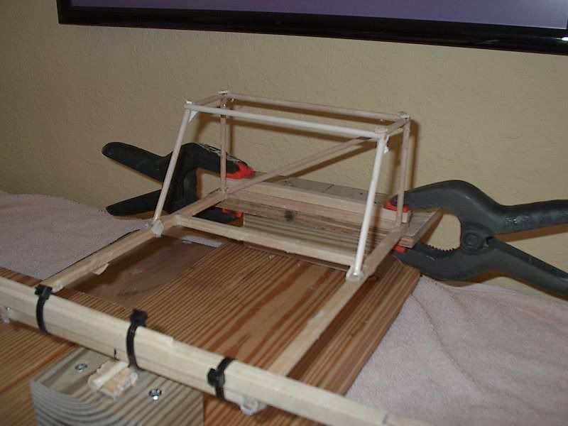
As the model shows, a four point cage in the vehicle interior leaves significant lengths of the wheelbase unmodified or unimproved. Plus, this configuration lacks the necessary bracing to prevent tube flexing when the frame is twisted.
Racer
Joined: Mar 2004
Posts: 292
Likes: 2
From: Plumas Lake CA
The older C3's used solid body mounts. I believe a good fabricator could beef-up the birdcage and run some tubes forward from the top of the firewall area to triangulate the front half of the car. These tubes could also be tied together, like the frame brace others have bolted between the upper control arms, at a high point before they bend down to attach to the front frame rails.
The "shark bar" at the rear kickup could then tie into the bodymount there. A pair of support tube could be attached to the upper cross bar and travel down to the rear frame rails, above the rear suspension area, to triangulate the rear.
Integrate solid (custom?) body mounts into the extra reinforcements points and you could still remove the body/skeleton and keep the extra bars fairly invisible. The week link would still be the door area, but your beefed side rails and torque tube would certainly help there.
Come to think of it, Norval did some interesting mounts for his bolt-in cage a few years ago!
Last edited by 1mpalss; Oct 8, 2008 at 10:28 PM. Reason: Remembered Norval Wilhelms bolt in rollcage