


C3 frame torsion testing
Thread Starter
Tech Contributor


Joined: Jun 2004
Posts: 20,934
Likes: 962
From: I tend to be leery of any guy who doesn't own a chainsaw or a handgun.
While working on my spare frame to install a C4 suspension, I noticed how flimsy these things are, particularly torsion-wise and even in beam strength. I started to do some frame modification modeling to see if I could improve the torsional strength of my setup. Here's one of the model configurations I looked at.
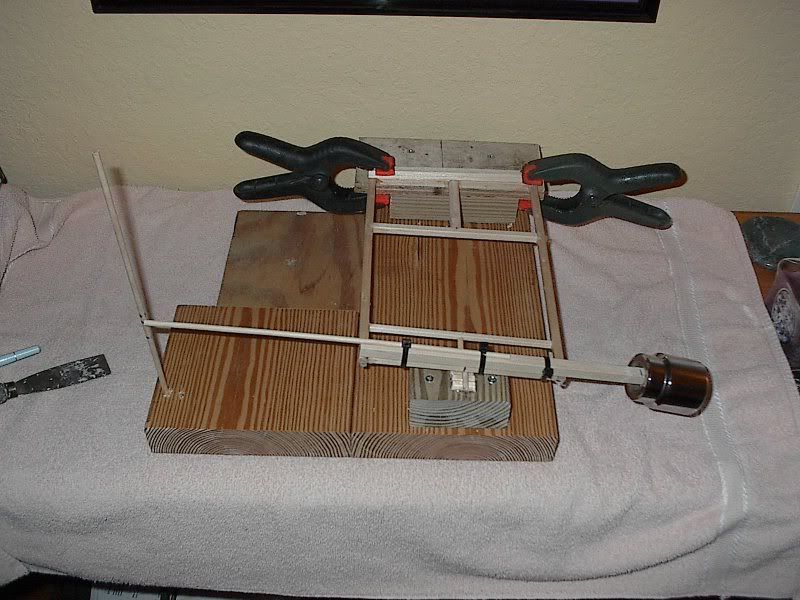
I added a torsion tube below the driveshaft to stiffen the frame area between the trans crossmember and the pinion crossmember. I also added a small crossmember connecting the motor mount horns, and a torsion bar connecting that to the front suspension crossmember.
Unseen in the picture are some diagonal struts, stiffening up the rear kickups, from the upper shock mounts to the pinion crossmember. I also cut open the interior walls of the frame rails between the trans crossmember and the motor mount horns, and installed 1 3/4 inch OD tubing inside the frame to add additional stiffness to this portion of the frame.
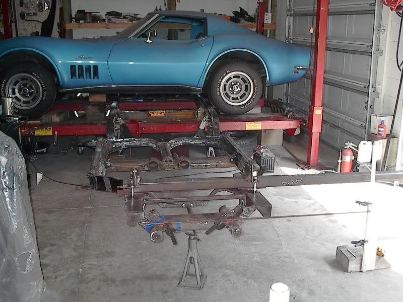
I'm currently applying about 1500 ft-lbs of torque to the frame looking for additional areas that may need reinforcing. The rear of the frame is anchored to my hoist (I'm using the engineless car as additional ballast to steady the anchor point). The setup is working reasonable well, but I'm getting a little warping on the lift runner, which then allows the rear frame area to twist a little, adding some error into my measurements. I'm currently modifying the runner/anchor area to eliminate the distortion so I can simplify things and only have to read the front frame twist angle for my torsion calculations.
I added a torsion tube below the driveshaft to stiffen the frame area between the trans crossmember and the pinion crossmember. I also added a small crossmember connecting the motor mount horns, and a torsion bar connecting that to the front suspension crossmember.
Unseen in the picture are some diagonal struts, stiffening up the rear kickups, from the upper shock mounts to the pinion crossmember. I also cut open the interior walls of the frame rails between the trans crossmember and the motor mount horns, and installed 1 3/4 inch OD tubing inside the frame to add additional stiffness to this portion of the frame.
I'm currently applying about 1500 ft-lbs of torque to the frame looking for additional areas that may need reinforcing. The rear of the frame is anchored to my hoist (I'm using the engineless car as additional ballast to steady the anchor point). The setup is working reasonable well, but I'm getting a little warping on the lift runner, which then allows the rear frame area to twist a little, adding some error into my measurements. I'm currently modifying the runner/anchor area to eliminate the distortion so I can simplify things and only have to read the front frame twist angle for my torsion calculations.
Team Owner


Joined: Sep 2006
Posts: 31,301
Likes: 4,390
From: Westminster Maryland
Hi 69,
What you're doing is pretty interesting.
Is it possible that the spring and shock rates will need to be recalibrated because you've increased the frame stiffness? Do you have a way of calculating that?
I wouldn't mind seeing more pictures!
Regards,
Alan
What you're doing is pretty interesting.
Is it possible that the spring and shock rates will need to be recalibrated because you've increased the frame stiffness? Do you have a way of calculating that?
I wouldn't mind seeing more pictures!
Regards,
Alan
Drifting


Joined: May 2008
Posts: 1,462
Likes: 43
From: Choctaw Country
Extremely interesting and insightful.
Just wondering about the intended frame flex that the vehicle is supposed to have. By doing this, and making things more tough, aren't you compromising the flex ability of the vehicle, and therefore asking for a bend, or a break, somewhere on up the line?

Just wondering about the intended frame flex that the vehicle is supposed to have. By doing this, and making things more tough, aren't you compromising the flex ability of the vehicle, and therefore asking for a bend, or a break, somewhere on up the line?
Thread Starter
Tech Contributor
Joined: Jun 2004
Posts: 20,934
Likes: 962
From: I tend to be leery of any guy who doesn't own a chainsaw or a handgun.
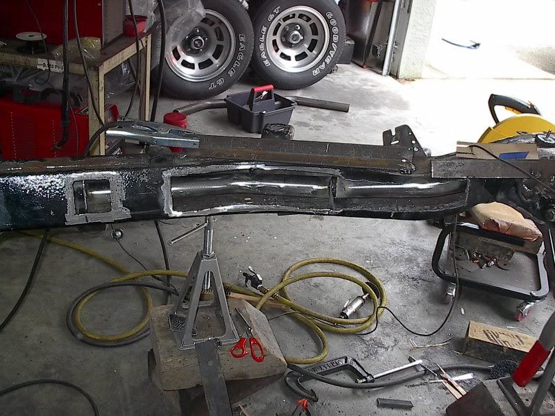
Below is a couple other pictures during some of the cutting and welding.
The first is the tubing I installed inside the front half of the frame to add some torsional stiffness to this area.
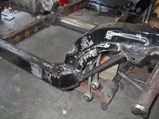
This next picture shows the rear struts to stiffen up the rear kickup area. I tied the rear shock mount down to the pinion crossmember. It also shows the torsion tube I added (bolt-in) between the trans and pinion crossmembers.
Thread Starter
Tech Contributor
Joined: Jun 2004
Posts: 20,934
Likes: 962
From: I tend to be leery of any guy who doesn't own a chainsaw or a handgun.
Extremely interesting and insightful.
Just wondering about the intended frame flex that the vehicle is supposed to have. By doing this, and making things more tough, aren't you compromising the flex ability of the vehicle, and therefore asking for a bend, or a break, somewhere on up the line?
Just wondering about the intended frame flex that the vehicle is supposed to have. By doing this, and making things more tough, aren't you compromising the flex ability of the vehicle, and therefore asking for a bend, or a break, somewhere on up the line?
Pro

Joined: Mar 2008
Posts: 655
Likes: 0
From: Sarasota Fl
Extremely interesting and insightful.
Just wondering about the intended frame flex that the vehicle is supposed to have. By doing this, and making things more tough, aren't you compromising the flex ability of the vehicle, and therefore asking for a bend, or a break, somewhere on up the line?
Just wondering about the intended frame flex that the vehicle is supposed to have. By doing this, and making things more tough, aren't you compromising the flex ability of the vehicle, and therefore asking for a bend, or a break, somewhere on up the line?
Race Director


Joined: Sep 1999
Posts: 11,361
Likes: 383
From: Plano TX
The trick will be to get the body and suspension on there without hitting the new braces. You're definitely doing a good thing. The less frame flex, the better. Flex was the reason GM went away from the X-type frames they used in the 50's. The ladder-style frame is much better than X-style, but can always be made better.
Corvette Stories
The Best of Corvette for Corvette Enthusiasts

Every 2027 Corvette Engine Explained
Joe Kucinski
Designer Imagines A Corvette That Looks More Like a Corvette Than the Corvette
Verdad Gallardo
10 Ugly Corvettes That We Still Kinda Love
Joe Kucinski
Top 10 Most Expensive Corvettes Ever Sold on Bring A Trailer
Brett Foote
10 Things Every Corvette Owner Needs (2026 Edition)
Michael S. Palmer
8 Most "Only Corvette Owners Understand" Quirks and Problems
Pouria Savadkouei
10 Reasons the C6 Z06 is Still A Performance Benchmark After 20 Years
Joe Kucinski
How Much Horsepower Every Corvette Engine "LOST" in 1972
Joe Kucinski
Top 10 DOs and DON'Ts for Protecting Your Convertible Top!
Michael S. Palmer
Thread Starter
Tech Contributor
Joined: Jun 2004
Posts: 20,934
Likes: 962
From: I tend to be leery of any guy who doesn't own a chainsaw or a handgun.
A cage requires cutting up the interior bodywork. This is a street car. And, most cages I've seen on street vehicles add very little to the frames torsional stiffness due to the poor design of the cage. Unless you tie all four corners of the wheelbase together, the cage is essentially ballast weight instead of chassis stiffening.

Melting Slicks

Joined: Mar 2008
Posts: 2,989
Likes: 198
From: Meriden CT
Umm...nope. Any properly designed cage will take up some room in the car but all the stuff you've been wasting your time on could have easily been added to the outside of the frame and still did as little good as what you're doing.
All you're doing to the side rails is adding material parrallel to the frame. That will do as little to add "torsional rigidity" as adding material directly to the outside of the rails. You are essentially just making the frame thicker. The "strut" you have welded behind the kickup has done zero to keep that welded portion of the frame from flexing. Your time would be better spent fitting a proper cage to the car, I can offer you some suggestions regarding that. If it's a street car, put a modern suspension in it for better capabilities.
All you're doing to the side rails is adding material parrallel to the frame. That will do as little to add "torsional rigidity" as adding material directly to the outside of the rails. You are essentially just making the frame thicker. The "strut" you have welded behind the kickup has done zero to keep that welded portion of the frame from flexing. Your time would be better spent fitting a proper cage to the car, I can offer you some suggestions regarding that. If it's a street car, put a modern suspension in it for better capabilities.
Melting Slicks

Joined: Dec 1999
Posts: 2,116
Likes: 156
From: Mid West
Cruise-In III Veteran
For the street, you cannot add a proper roll-cage in the older C3's due to the flat back window without being a danger to your head (unless your really short). I've thought about adding a cage to my 76, but a nice solid bar right behind my head does not seam like a good idea to me when driving on the street without a helmet.
Obviously a cage is the most direct route to stiffen a frame and I have one in my Cutlass that I use for drag racing, but they are not street friendly nor do most passengers like to deal with them. I can see where 69427 is coming from and encourage you to keep researching.
The only thing I've done to stiffen my chassis so far is one of things SH-60B suggested. I welded plates on the outside and bottom of the frame rails between the wheels. I know its not the best for adding torsional stiffness, but its a start. Next is to weld some diagonal supports between the frame rails this winter.


Thread Starter
Tech Contributor
Joined: Jun 2004
Posts: 20,934
Likes: 962
From: I tend to be leery of any guy who doesn't own a chainsaw or a handgun.
Thread Starter
Tech Contributor
Joined: Jun 2004
Posts: 20,934
Likes: 962
From: I tend to be leery of any guy who doesn't own a chainsaw or a handgun.
Umm...nope. Any properly designed cage will take up some room in the car but all the stuff you've been wasting your time on could have easily been added to the outside of the frame and still did as little good as what you're doing.
All you're doing to the side rails is adding material parrallel to the frame. That will do as little to add "torsional rigidity" as adding material directly to the outside of the rails. You are essentially just making the frame thicker. The "strut" you have welded behind the kickup has done zero to keep that welded portion of the frame from flexing. Your time would be better spent fitting a proper cage to the car, I can offer you some suggestions regarding that. If it's a street car, put a modern suspension in it for better capabilities.
All you're doing to the side rails is adding material parrallel to the frame. That will do as little to add "torsional rigidity" as adding material directly to the outside of the rails. You are essentially just making the frame thicker. The "strut" you have welded behind the kickup has done zero to keep that welded portion of the frame from flexing. Your time would be better spent fitting a proper cage to the car, I can offer you some suggestions regarding that. If it's a street car, put a modern suspension in it for better capabilities.
Last edited by 69427; Sep 27, 2008 at 10:58 PM. Reason: Shortened for brevity.
Thread Starter
Tech Contributor
Joined: Jun 2004
Posts: 20,934
Likes: 962
From: I tend to be leery of any guy who doesn't own a chainsaw or a handgun.
The trick will be to get the body and suspension on there without hitting the new braces. You're definitely doing a good thing. The less frame flex, the better. Flex was the reason GM went away from the X-type frames they used in the 50's. The ladder-style frame is much better than X-style, but can always be made better.
 )
)
Pro
Joined: Mar 2008
Posts: 655
Likes: 0
From: Sarasota Fl
Umm...nope. Any properly designed cage will take up some room in the car but all the stuff you've been wasting your time on could have easily been added to the outside of the frame and still did as little good as what you're doing.
All you're doing to the side rails is adding material parrallel to the frame. That will do as little to add "torsional rigidity" as adding material directly to the outside of the rails. You are essentially just making the frame thicker. The "strut" you have welded behind the kickup has done zero to keep that welded portion of the frame from flexing. Your time would be better spent fitting a proper cage to the car, I can offer you some suggestions regarding that. If it's a street car, put a modern suspension in it for better capabilities.
All you're doing to the side rails is adding material parrallel to the frame. That will do as little to add "torsional rigidity" as adding material directly to the outside of the rails. You are essentially just making the frame thicker. The "strut" you have welded behind the kickup has done zero to keep that welded portion of the frame from flexing. Your time would be better spent fitting a proper cage to the car, I can offer you some suggestions regarding that. If it's a street car, put a modern suspension in it for better capabilities.
Melting Slicks
Joined: Mar 2008
Posts: 2,989
Likes: 198
From: Meriden CT
The list of nonsense you've offered here is impressive. It sounds familiar. I've had discussions with you in the past where I put up with several bouts of rudeness and junior high level sarcasm from you after I disagreed with you. It ended up being an unproductive use of my time, and I don't have the energy or patience to put up with you again. Please take your silliness elsewhere.
Last edited by SH-60B; Sep 28, 2008 at 06:15 AM.
Melting Slicks
Joined: Mar 2008
Posts: 2,989
Likes: 198
From: Meriden CT
Racer

Joined: Mar 2005
Posts: 294
Likes: 1
From: Racine Wisconsin
69427 Nice job of performing some interesting research. Your torsion tube idea is analogous to the effect of an "anti-sway" bar. I think it would also transfer more torque to the wheels as well. Relative to the description of torsion resistance in your wooden model, do you have an idea about how much the torsion tube stiffened the frame? For example, 1" less deflection with 1000# asymmetric loading, etc. An idea for you: Some racing organizations require that safety hoops be installed to restrain a "flailing" drive shaft. Your torsion tube around the drive shaft would accomplish two functions. You would probably need to have the torsion tube attached to ladder components that could be unbolted for servicing the u-joints.
Thread Starter
Tech Contributor
Joined: Jun 2004
Posts: 20,934
Likes: 962
From: I tend to be leery of any guy who doesn't own a chainsaw or a handgun.
I was offering some criticism but also some assistance and I get insults in return. You are very quick to accept posts that agree with you 100%, but anything less and you get angry. Perhaps you should do some growing up. What is silly is what you are doing to that frame - not me.
Regarding the engineering and physics reasons for these changes, I have spoken to several very experienced fabricators and engineers on other forums, and have listened to their learned opinions. Regarding you, I have yet to hear or see evidence of what your schooling or technical expertise is. I do not consider the gift of sarcasm as a useful tool in chassis tuning.
And, unless that's your grandmother's car in your avatar, the suspension that has been fitted to this frame is decades more modern than yours.
Now, once again, please go away.