





What wire is this?,..under dash.

Thread Starter
Melting Slicks


Joined: Mar 2005
Posts: 2,838
Likes: 10
From: Austin TX
 What wire is this?,..under dash.
http://s421.photobucket.com/albums/p...t=PB130001.jpg
As you can see in the photo, there's a brown wire with a male connector then a female connector with a black wire that's cut. I can't find what it was cut from. This is a 73, fully loaded.
Edit. Here's the same wire on a brand new wiring harness. I still don't know to what it attaches.
http://s421.photobucket.com/albums/p...sunderdash.jpg
Please enlighten me. Thanks!
As you can see in the photo, there's a brown wire with a male connector then a female connector with a black wire that's cut. I can't find what it was cut from. This is a 73, fully loaded.
Edit. Here's the same wire on a brand new wiring harness. I still don't know to what it attaches.
http://s421.photobucket.com/albums/p...sunderdash.jpg
Please enlighten me. Thanks!
Last edited by 73, Dark Blue 454; Nov 14, 2008 at 11:07 PM.
Thread Starter
Melting Slicks
Joined: Mar 2005
Posts: 2,838
Likes: 10
From: Austin TX
I'm looking at page 403 of the 73 Assy Manual, and,..could the cut wire go to the "radio cpacitor connection" shown on that page? If so, does somebody have a photo of what it is and where it goes?
Thanks!
Thanks!

Race Director

Joined: May 2006
Posts: 16,528
Likes: 53
From: Dayton, Ohio
I looked for a pic but the 2 I have wont help you.It looks like a condenser that goes with your points in the dist.It should mount to the housing that holds your pedals close to the ignition switch.If i remember right it will be in about the same hoop that holds the condenser in the dist.
Team Owner


Joined: Jan 2006
Posts: 37,637
Likes: 3,116
From: Crossville TN
I believe that is for the "spike suppressing" capacitor that works with the brake light switch (on the brake pedal linkage). It prevents a "pop" noise in the radio when the brakes are applied.
Corvette Stories
The Best of Corvette for Corvette Enthusiasts

Top 10 Most Explosive Corvettes Ever Made: Power-to-Weight Ratio Ranked!
Joe Kucinski
150 hp to 1,250 hp: Every Corvette Generation Compared by the Specs That Matter
Joe Kucinski
8 Coolest Corvette Pace Cars (and Replicas) of All Time
Verdad Gallardo
Top 10 Corvette Engines RANKED by Peak Torque (70+ Years of Muscle!)
Joe Kucinski
Corvette ZR1X Will Be Pacing the Indy 500, And Could Probably Race, Too!
Verdad Gallardo
Top 10 Corvettes Coming to Mecum Indy 2026!
Brett Foote
Top 10 C9 Corvette MUST-HAVES to Fix These C8 Generation Flaws!
Michael S. Palmer
10 Revolutionary 'Corvette Firsts' Most People Don't Know
Joe Kucinski
5 Reasons to Upgrade to an LS6-Powered Corvette; 5 Reasons to Stay LT2
Michael S. Palmer
Thread Starter
Melting Slicks
Joined: Mar 2005
Posts: 2,838
Likes: 10
From: Austin TX
Here's the same wire on a brand new under-dash wiring harness. As you can tell, it exits the harness at the same place as the wiring for the ignition switch and other wires that attach to the steering column.
Does this help confirm what it is?
http://s421.photobucket.com/albums/p...sunderdash.jpg
Does this help confirm what it is?
http://s421.photobucket.com/albums/p...sunderdash.jpg
Last edited by 73, Dark Blue 454; Nov 14, 2008 at 11:07 PM.
Racer

Joined: Jun 2007
Posts: 274
Likes: 2
From: Finger TN
Doc Rebuild oOSOEZ schematic
My '73 doc rebuild schematic shows that single connector and brown wire as the radio capacitor conn. on Ign Switch, so 7T1vette is correct. I also recall that connector when I took my '73 apart.
Last edited by r3rep; Nov 14, 2008 at 11:49 PM. Reason: spelling

Safety Car


Joined: Apr 2002
Posts: 4,653
Likes: 6
From: North Royalton, OH
St. Jude Donor '06-'07
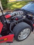
Dead center in this pic you can see the capacitor and its mount bracket, just behind the heavy fiber optic cabling. Not sure if that's where it's supposed to attach, but that's where mine is. 

Team Owner
Joined: Jan 2006
Posts: 37,637
Likes: 3,116
From: Crossville TN
That appears to be a 'different' noise suppressing capacitor. The one for the brake light switch is attached to the brake pedal linkage above the pedal. I do believe that all of those capacitors [used throughout the vehicle] had the same capacitance value.
Race Director
Joined: May 2006
Posts: 16,528
Likes: 53
From: Dayton, Ohio
Bottom line its JUST a cap.As 7T1 says its the same value as the rest.If you buy it with the "correct" male connector I've seen them for around $25 or you can crimp your own on and functionally be done.If you have a late model radio you can just leave it unplugged and you probably wont even notice its gone.
The one in BSiegPaints pic is not in the correct location but will work fine if what its mounted to is grounded good.

Le Mans Master

Joined: Jul 2006
Posts: 8,117
Likes: 104
From: charlotte north carolina
not withstanding the advice of DW (whose knowledge of these cars i respect), i believe that the brn wire in question is not for a radio capacitor. not that it will make any difference in this case, because wiring a cap to this wire will not hurt (or help) anything. first, why would the general run a separate 12 gauge wire to that area for a capacitor whose current load is much less than 1 amp? second, noise caps are always connected between the hot and ground side of the subject device leads near the device, due to the impedance of the wiring harness. think of the brake switch cap and the turn signal cap. lastly, in an a/c car, power must be supplied to the a/c harness to activate the compressor clutch. when i married a 76 a/c unit to my 70, the only 12v wire that seemed to be in the correct position was this brn wire. it was an educated guess because there wasn't any detailed info on this wire that i could find, but it works.
again, i'm not posting this to get in a pissing contest with anybody, i'm just questioning the responses given.
again, i'm not posting this to get in a pissing contest with anybody, i'm just questioning the responses given.
Safety Car
Joined: Apr 2002
Posts: 4,653
Likes: 6
From: North Royalton, OH
St. Jude Donor '06-'07
DW - I'd love to know where it's really supposed to go - I'm getting ready to tear everything apart again as I add a/c to the car. If you've got a pic or could describe the location to me, it's much appreciated! Mine's always just been tucked under the console and grounded to the center support. Never looked right to me, but I never had another correct car to look at!
Race Director
Joined: May 2006
Posts: 16,528
Likes: 53
From: Dayton, Ohio
 when someone wants to discuss the (to most) boring part of the car...wiring and vacuum.Jnb you could be totally correct about that lead being for the AC when the car requires it...that would make sense.Its a shame I know but I dont have a schematic for an AC car.
 But on the non-AC cars the brown is ended with a cap.I've gotten cars in with popping through the stock radio when you would shift into 3rd or 4th gear or it might be out of those gears.I'm sorta guessing when I assumed that was the TCS solenoid working.What I would find is the brown was unplugged from the cap or like the OP the wire was broken off the cap.When I would reattach the pop would go away.Here is a diagram for a 71 that shows the cap at the end of the brown wire,marked with red X.
Race Director
Joined: May 2006
Posts: 16,528
Likes: 53
From: Dayton, Ohio
DW - I'd love to know where it's really supposed to go - I'm getting ready to tear everything apart again as I add a/c to the car. If you've got a pic or could describe the location to me, it's much appreciated! Mine's always just been tucked under the console and grounded to the center support. Never looked right to me, but I never had another correct car to look at!
I'm about 98% sure the cap mounts to the steering column or the pedal housing.CF member Duke had a great pic of the pedal housing in another thread but I cant remember if the cap was in the pic.
I'll see if I can find you a pic of it. Doesnt someone have this in the assembly manual?
Safety Car
Joined: Apr 2002
Posts: 4,653
Likes: 6
From: North Royalton, OH
St. Jude Donor '06-'07