


I've been working on replacing my headlamp assemblies and I misplaced the pages showing the radiator to bumper support rod and the headlamp relay mounting plate. Does anybody have access to one?
I took my pages out to work on the car a while ago and never put them back in the binder.
The 1970 model has an angled steel plate on which the two headlamp relay valves are mounted. I need to orient this plate to the headlamp support cross member which I just glued back into place. I'm also having a heck of a time determining where the front J hooks should be placed. Oh...and I need help determining the correct mounting orientation of the horns.
I need lots of help. Thanks in advance.
Matt
Quote:
Link1
Link2
Link3
Thanks Jerry.Originally Posted by Z-man
Are these any help? I'm not quite sure what you're looking for, and then what section of the manual they'd be in...Link1
Link2
Link3
These are close to what I need. What I was looking for was the radiator support rod pic and the plate which holds the relay (in fig 2). This diagram shows what looks like a newer Vette with a radiator cap. The 70 has the cap on the expansion tank. Fig 2 also shows one relay instead of the two attached to the angled metal plate which mounts on the "crossmember" below the nose.
The support rod attaches from the bottom of the radiator support to the nose brace. The headlight relay bracket is a one year only thing IIRC. I've never seen one for sale used, other years the relays were attached directly to the support bar.
Not sure what you mean by the "J hooks". I'll try to remember to throw the assembly manual in the car to scan the pages tomorrow at work.
Jim
Not sure what you mean by the "J hooks". I'll try to remember to throw the assembly manual in the car to scan the pages tomorrow at work.
Jim
Quote:
I took my pages out to work on the car a while ago and never put them back in the binder.
The 1970 model has an angled steel plate on which the two headlamp relay valves are mounted. I need to orient this plate to the headlamp support cross member which I just glued back into place. I'm also having a heck of a time determining where the front J hooks should be placed. Oh...and I need help determining the correct mounting orientation of the horns.
I need lots of help. Thanks in advance.
Matt
Originally Posted by 70454
I've been working on replacing my headlamp assemblies and I misplaced the pages showing the radiator to bumper support rod and the headlamp relay mounting plate. Does anybody have access to one?I took my pages out to work on the car a while ago and never put them back in the binder.
The 1970 model has an angled steel plate on which the two headlamp relay valves are mounted. I need to orient this plate to the headlamp support cross member which I just glued back into place. I'm also having a heck of a time determining where the front J hooks should be placed. Oh...and I need help determining the correct mounting orientation of the horns.
I need lots of help. Thanks in advance.
Matt
Quote:
Not sure what you mean by the "J hooks". I'll try to remember to throw the assembly manual in the car to scan the pages tomorrow at work.
Jim
JimOriginally Posted by 70BBvert
The support rod attaches from the bottom of the radiator support to the nose brace. The headlight relay bracket is a one year only thing IIRC. I've never seen one for sale used, other years the relays were attached directly to the support bar. Not sure what you mean by the "J hooks". I'll try to remember to throw the assembly manual in the car to scan the pages tomorrow at work.
Jim
Thanks.
The headlight relay orientation on the metal plate is what I'm looking for. From what I remember, this should be found on the same diagram as the support rod.
I took some pictures of 1970's a while back. I concentrated on the underside of the nose.
The J hooks hold the wiring harness and vacuum hoses.
Quote:
Thanks.
The headlight relay orientation on the metal plate is what I'm looking for. From what I remember, this should be found on the same diagram as the support rod.
I took some pictures of 1970's a while back. I concentrated on the underside of the nose.
The J hooks hold the wiring harness and vacuum hoses.
On the skirts or on the headlight support brace? Originally Posted by 70454
JimThanks.
The headlight relay orientation on the metal plate is what I'm looking for. From what I remember, this should be found on the same diagram as the support rod.
I took some pictures of 1970's a while back. I concentrated on the underside of the nose.
The J hooks hold the wiring harness and vacuum hoses.
Jim
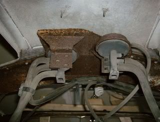
This is from an untouched original 70 front clip I have. That plates mounts to the header bar with 3 pan head screws. BTW any repop header bar does not have the 3 thread provisions for that plate. They all have 4 thread provisions since, as someone stated, the relays mount to the header directly other than 70. (2 screws for each)

Here's the manual pics. There is a plastic push in fastener in the wire harness that attaches in the center between the horns. Not shown in manual


Here's the manual pics. There is a plastic push in fastener in the wire harness that attaches in the center between the horns. Not shown in manual

70454, I just took my center support rod out to straighten it a couple of weeks ago and went all through my '72 shop manual and A.I.M. but never found a page with that rod on it.
It was a b---h to put back in. That bolt that goes into the nose support is halfway obscurred by the bumper. And there's only about the width of an index finger to maneuver it into place. It took one finger on each side of the bolt to get it aligned and started. Only about 2 hours work.
If your bumper isn't installed yet you're in good shape.
Good luck.
cc
Corvette Stories
The Best of Corvette for Corvette Enthusiasts
Explore

Corvette ZR1X Will Be Pacing the Indy 500, And Could Probably Race, Too!
Verdad Gallardo
Top 10 Corvettes Coming to Mecum Indy 2026!
Brett Foote
Top 10 C9 Corvette MUST-HAVES to Fix These C8 Generation Flaws!
Michael S. Palmer
10 Revolutionary 'Corvette Firsts' Most People Don't Know
Joe Kucinski
5 Reasons to Upgrade to an LS6-Powered Corvette; 5 Reasons to Stay LT2
Michael S. Palmer
2027 Corvette vs The World: Every C8 vs Its Closest Competitor
Joe Kucinski
10 Most Common Corvette Problems of the Last 20 Years!
Joe Kucinski
5 MOST and 5 LEAST Popular Corvette Model Years in History!
Joe Kucinski
2027 Corvette Buyer's Guide: Everything You Need to Know!
Joe KucinskiQuote:
These are close to what I need. What I was looking for was the radiator support rod pic and the plate which holds the relay (in fig 2). This diagram shows what looks like a newer Vette with a radiator cap. The 70 has the cap on the expansion tank. Fig 2 also shows one relay instead of the two attached to the angled metal plate which mounts on the "crossmember" below the nose.
Those pix are from the '70 assembly manual (which also covered '69). I'll try and get a couple of pictures from my stock front end.Originally Posted by 70454
Thanks Jerry.These are close to what I need. What I was looking for was the radiator support rod pic and the plate which holds the relay (in fig 2). This diagram shows what looks like a newer Vette with a radiator cap. The 70 has the cap on the expansion tank. Fig 2 also shows one relay instead of the two attached to the angled metal plate which mounts on the "crossmember" below the nose.
Thanks Guys. You're all awesome!
Dennis.
It looks like you nailed it. The 70 Vette has some odd stuff about it, including the mounting plate to the header bar as shown in your second Mid-America diagram (BTW...this is the one missing from my manual).
Dennis.
It looks like you nailed it. The 70 Vette has some odd stuff about it, including the mounting plate to the header bar as shown in your second Mid-America diagram (BTW...this is the one missing from my manual).
Quote:
Thanks Z. Sometimes pics help in assembly more than the manuals. I'm trying to visualise the hose routing and placement of the actuators.Originally Posted by Z-man
Those pix are from the '70 assembly manual (which also covered '69). I'll try and get a couple of pictures from my stock front end.
Also...while I'm on the subject. It is noted that the 1970 hose routing to the actuators have some glitches such as a green hose to a yellow color patch on the actuator on the right side. Can anybody verify the headlamp actuator hose order for the green, red and yellow hoses? My shop manual shows these in black and white and the pictures are hand drawn (1971 shop manual - since 70 was a strike year)
Thanks
I think Dennis got most of it. That MA manual is really good. Mine looks to be a combination of '69 and '70 (due to the low '70 production numbers). The hose routing in that sketch aren't what they are like at all!
I held my camera down behind the horns and thought I'd get a good bunch of pix, but they didn't come out too well. I'll do it again from a little different perspective so you can see the valves and the horns. The hoses appear to be run just like in Dennis' pictures, although the colored stripes have long since evaporated or worn off. Here they are so far...
Passenger side

Driver's Side

Center

From the front

I held my camera down behind the horns and thought I'd get a good bunch of pix, but they didn't come out too well. I'll do it again from a little different perspective so you can see the valves and the horns. The hoses appear to be run just like in Dennis' pictures, although the colored stripes have long since evaporated or worn off. Here they are so far...
Passenger side
Driver's Side
Center
From the front

My 70 has the 4 mounting holes for the direct mounting of the relays. I'd like to mount the steel angled plate this weekend. I'm gonna try to use the existing holes in the header bar but I think this is whats causing my dilema. Once the plate is overlaid on the holes in the header bar, it puts it out of position......the hoses would be directly on the bumper support bar(s) which support the nose. Hmmm...
Luckily, I was able to mount the steel plate to the header bar using one of the 4 holes used to directly mount the relays. I may simply tap another hole and insert one more screw to hold it tight. The hoses are back on and the headlamps work. I will be spending the day shoring up the vacuum lines and wiring and inserting the bulbs and retainers.
Quote:
I was in the same situation when I replaced my header bar. Since I still had the originalI was able to template where the 3 holes would be on the 4 hole bar. I believe I was able to use 2 of the 4 holes and added the one I needed to install the mounting plate. Originally Posted by 70454
Luckily, I was able to mount the steel plate to the header bar using one of the 4 holes used to directly mount the relays. I may simply tap another hole and insert one more screw to hold it tight. The hoses are back on and the headlamps work. I will be spending the day shoring up the vacuum lines and wiring and inserting the bulbs and retainers.
I bought a threaded rivet tool. Drilled the hole in the bar inserted the threaded rivet, and was even able to use the original pan head screw for a perfect match to the original
Quote:
I bought a threaded rivet tool. Drilled the hole in the bar inserted the threaded rivet, and was even able to use the original pan head screw for a perfect match to the original
Good move. My neighbor has a much better set of tools. I'll have him over to check it out. Originally Posted by dennis
I was in the same situation when I replaced my header bar. Since I still had the originalI was able to template where the 3 holes would be on the 4 hole bar. I believe I was able to use 2 of the 4 holes and added the one I needed to install the mounting plate. I bought a threaded rivet tool. Drilled the hole in the bar inserted the threaded rivet, and was even able to use the original pan head screw for a perfect match to the original
I've moved on to the headlamps and headlamp retainers. They're marked A, B, C, & D. I took them off to repaint and I'm working on the puzzle of putting them back in the right place so the bulbs are seated properly. Progress is good.
Quote:
I've moved on to the headlamps and headlamp retainers. They're marked A, B, C, & D. I took them off to repaint and I'm working on the puzzle of putting them back in the right place so the bulbs are seated properly. Progress is good.
On either Wilcox's or Keens website they're labled. Just go on as if you as if you were buying them Originally Posted by 70454
Good move. My neighbor has a much better set of tools. I'll have him over to check it out. I've moved on to the headlamps and headlamp retainers. They're marked A, B, C, & D. I took them off to repaint and I'm working on the puzzle of putting them back in the right place so the bulbs are seated properly. Progress is good.
 Couldn't find the labels in the AIM.
Edit; from Keens website
240028 Headlight Bulb Cup C Outer RH 58-82 Except 64-67 $15.00 1 $15.00
240027 Headlight Bulb Cup A Outer LH 58-82 $15.00 1 $15.00
240026 Headlight Bulb Cup B Inner RH 58-82 $15.00 1 $15.00
240025 Headlight Bulb Cup D Inner LH 58-82 Except 64-67
Jim
Quote:
Couldn't find the labels in the AIM.
Edit; from Keens website
240028 Headlight Bulb Cup C Outer RH 58-82 Except 64-67 $15.00 1 $15.00
240027 Headlight Bulb Cup A Outer LH 58-82 $15.00 1 $15.00
240026 Headlight Bulb Cup B Inner RH 58-82 $15.00 1 $15.00
240025 Headlight Bulb Cup D Inner LH 58-82 Except 64-67
Jim
Thanks.Originally Posted by 70BBvert
On either Wilcox's or Keens website they're labled. Just go on as if you as if you were buying them Couldn't find the labels in the AIM.Edit; from Keens website
240028 Headlight Bulb Cup C Outer RH 58-82 Except 64-67 $15.00 1 $15.00
240027 Headlight Bulb Cup A Outer LH 58-82 $15.00 1 $15.00
240026 Headlight Bulb Cup B Inner RH 58-82 $15.00 1 $15.00
240025 Headlight Bulb Cup D Inner LH 58-82 Except 64-67
Jim
That's how they came out. The bulbs have "male" nubs which fall into place on the notches on the bulb cups. The easy way to mount these is to get the high beam / low beam orientation set before pluging any bulb cups or bulbs. These can be laid out in front of the car and installed one by one.
Great find.
Thanks
I'm working on the front end reassembly now.
I was wondering about the wiring routing in regards to the headlamp bulb plugs. How do they route from the harness down to the lights? Do they sneak through or around the headlamp "group" frame.
The above diagram shows the routing for the turn signal bulb and side marker bulb. This is a great photo but the "wrapping" of the wires around the J-Hook is quite uncomfortable.