


1971 CEC Solenoid Wiring

Thread Starter
Melting Slicks


Joined: Apr 2010
Posts: 2,796
Likes: 1,197
From: Canberra Australia
2025 C3 of the Year Finalist - Modified
Hi
I have read all the posts I could find (including the NCRS article) about the 1971 specific CEC solenoid wiring as well as going through the revised 1971 wiring diagrams. However I am still a bit confused
So I have attempted to trace the wires and have taken apart the relays and am working on a diagram to understand how it works.
Not finished yet and I still need a little help please.

Delay Relay
At startup it provides earth to fire the carb solenoid.
After 10-15 seconds that earth is dropped and its up to the Reverse Relay to do its work.
After pulling the Delay Relay apart it appears to be bimetal strip wrapped in resistance wire. Once powered on ignition start it heats up and breaks the contacts after 10+ seconds.
There is possibly some form of resistance in the brown/white wire to stop overheating the bimetal strip (on 12v it gets very hot :-).
Reverse Relay
The Reverse Relay will triggers if the transmission gear switch earths out and then the relay provides earth to fire the carb solenoid.
Thermal Switch
What confuses me (and it does not take much) is the temperature sender/thermal switch in the passenger head.
From all diagrams, and from my wire tracing it seems to be fed 12 volts as it is wired to the same terminal that powers the resistance wire in the delay relay (brown//white) then has a loop of wire to the second terminal on the sender (I am missing those wires).
So I am stuck - I cant see how the thermal switch in the head effects the reverse relay as its not connected at all.
One possibility I thought of was the thermal switch provides an alternate path to earth (lower resistance) thus robbing the resistance wire in the delay relay of enough power to deflect the bimetal strip and again giving earth to fire the carb solenoid
Am I way off ?
Any thoughts would be appreciated.
I have read all the posts I could find (including the NCRS article) about the 1971 specific CEC solenoid wiring as well as going through the revised 1971 wiring diagrams. However I am still a bit confused
So I have attempted to trace the wires and have taken apart the relays and am working on a diagram to understand how it works.
Not finished yet and I still need a little help please.
Delay Relay
At startup it provides earth to fire the carb solenoid.
After 10-15 seconds that earth is dropped and its up to the Reverse Relay to do its work.
After pulling the Delay Relay apart it appears to be bimetal strip wrapped in resistance wire. Once powered on ignition start it heats up and breaks the contacts after 10+ seconds.
There is possibly some form of resistance in the brown/white wire to stop overheating the bimetal strip (on 12v it gets very hot :-).
Reverse Relay
The Reverse Relay will triggers if the transmission gear switch earths out and then the relay provides earth to fire the carb solenoid.
Thermal Switch
What confuses me (and it does not take much) is the temperature sender/thermal switch in the passenger head.
From all diagrams, and from my wire tracing it seems to be fed 12 volts as it is wired to the same terminal that powers the resistance wire in the delay relay (brown//white) then has a loop of wire to the second terminal on the sender (I am missing those wires).
So I am stuck - I cant see how the thermal switch in the head effects the reverse relay as its not connected at all.
One possibility I thought of was the thermal switch provides an alternate path to earth (lower resistance) thus robbing the resistance wire in the delay relay of enough power to deflect the bimetal strip and again giving earth to fire the carb solenoid
Am I way off ?
Any thoughts would be appreciated.
Last edited by CraigH; Mar 13, 2019 at 05:23 PM.
Team Owner


Joined: Sep 2006
Posts: 31,301
Likes: 4,389
From: Westminster Maryland
Hi Craig,
I don't understand how the 71 CEC system works well enough to help you.
Do you have the CEC electrical diagram and the information describing the system from the 71 GM CHASSIS SERVICE MANUAL? If not, I'll scan it and post it for you; they may help you.
Regards,
Alan
I don't understand how the 71 CEC system works well enough to help you.
Do you have the CEC electrical diagram and the information describing the system from the 71 GM CHASSIS SERVICE MANUAL? If not, I'll scan it and post it for you; they may help you.
Regards,
Alan
Thread Starter
Melting Slicks
Joined: Apr 2010
Posts: 2,796
Likes: 1,197
From: Canberra Australia
2025 C3 of the Year Finalist - Modified
Hi Craig,
I don't understand how the 71 CEC system works well enough to help you.
Do you have the CEC electrical diagram and the information describing the system from the 71 GM CHASSIS SERVICE MANUAL? If not, I'll scan it and post it for you; they may help you.
Regards,
Alan
I don't understand how the 71 CEC system works well enough to help you.
Do you have the CEC electrical diagram and the information describing the system from the 71 GM CHASSIS SERVICE MANUAL? If not, I'll scan it and post it for you; they may help you.
Regards,
Alan
I have a Chilton Repair Manual and a Motorbooks Shop Manual but not the 71 GM Chassis Service Manual.
A copy of the relevant part would be great.
The problem is the numerous bits of doco I have seem different in every case and then different again when i compare to my actual harness.
I will probably bypass the vacuum solenoids operation anyway but I want to try and work out how it is meant to work.
One other thing I did find was that power to the Tan and Brown/white wires does not cut when ignition is off, rather it slowly goes down. Have just found that if the car has an auto and A/C there is a solid state module to keep power to the A/C circuit for 3 seconds to stop dieseling - Another variable :-)
Am going to consult a few friends who have deeper skills in electronics etc as well.
Race Director


Joined: Jul 2001
Posts: 15,892
Likes: 42
I know little of the '71 CEC system other than believe the switch in the R/H head acts as a ground (earth) for either low or high coolant temperature conditions.
If the brown/white wire has 12V at all times and it is connected upstream of the resistance coil then this would be a direct short. That can't be right.
If the brown/white wire has 12V at all times and it is connected upstream of the resistance coil then this would be a direct short. That can't be right.

Le Mans Master

Joined: Dec 2003
Posts: 5,727
Likes: 39
From: Fremont CA
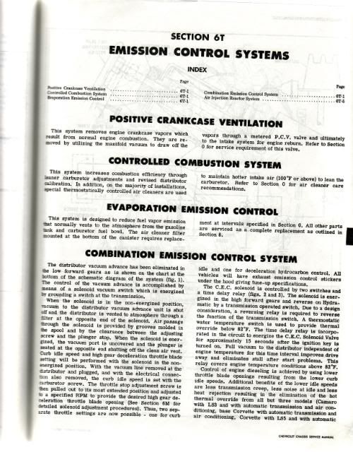
The 2 prong temprature switch on the passenger side cylider head goes between the soleniod ground (or "earth" as you taxed for royalty subjects say ) and the transmission gear switch (mounted on the side cover of the 4 speed.) This is done to allow the CEC soleniod to only function when the motor is up to operating temprature as it retards spark advance until 3rd/4th gear are selected and the transmission switch then grounds the soleniod coil to allow full spark advance at cruising speeds on the highway.
The CEC spark control system reduces engine performance and causes operating coolant tempratures to run higher, if OZ dosen't require emissions systems to be in full operation, I would run the vacuum signal directly to the carburator for better performance and mileage.
Note of conceeding a point with the "Borg" you were correct in the fact that transmission micro switch functions in 3rd/4th gear on a 4 speed transmission. Sometimes even you guys can contribute some positive information to a thread
) and the transmission gear switch (mounted on the side cover of the 4 speed.) This is done to allow the CEC soleniod to only function when the motor is up to operating temprature as it retards spark advance until 3rd/4th gear are selected and the transmission switch then grounds the soleniod coil to allow full spark advance at cruising speeds on the highway. The CEC spark control system reduces engine performance and causes operating coolant tempratures to run higher, if OZ dosen't require emissions systems to be in full operation, I would run the vacuum signal directly to the carburator for better performance and mileage.
Note of conceeding a point with the "Borg" you were correct in the fact that transmission micro switch functions in 3rd/4th gear on a 4 speed transmission. Sometimes even you guys can contribute some positive information to a thread
Team Owner
Joined: Sep 2006
Posts: 31,301
Likes: 4,389
From: Westminster Maryland
Hi Craig,
Here are the pages from the GM CSM. I hope they're of some help!
Regards,
Alan
PS: If your CEC solenoid happens to have it's original 'caution' lable on it I'd love to see a picture!!
Here are the pages from the GM CSM. I hope they're of some help!
Regards,
Alan
PS: If your CEC solenoid happens to have it's original 'caution' lable on it I'd love to see a picture!!
Thread Starter
Melting Slicks
Joined: Apr 2010
Posts: 2,796
Likes: 1,197
From: Canberra Australia
2025 C3 of the Year Finalist - Modified
I know little of the '71 CEC system other than believe the switch in the R/H head acts as a ground (earth) for either low or high coolant temperature conditions.
If the brown/white wire has 12V at all times and it is connected upstream of the resistance coil then this would be a direct short. That can't be right.
If the brown/white wire has 12V at all times and it is connected upstream of the resistance coil then this would be a direct short. That can't be right.
I agree
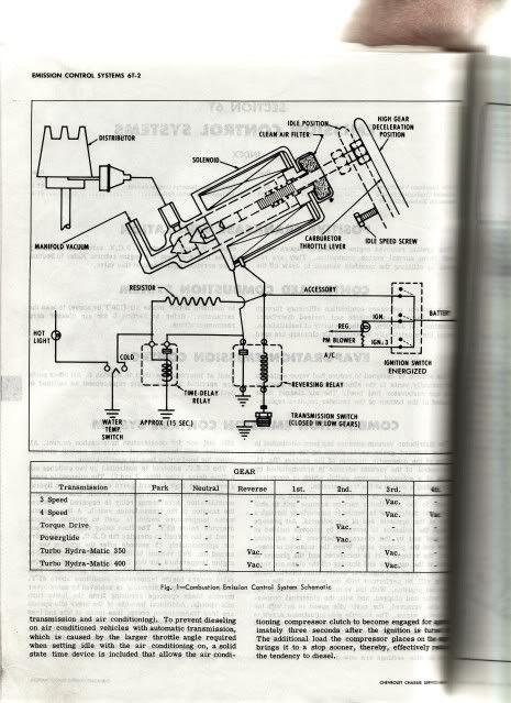
However have a look at the diagram Alan posted and it also shows the power wire connected via a resistor to the temperature switch.
It would make more sense if it was connected to the wire that joins both relays and then offers an alternate path to earth (Ground:-)
It also shows a Hot Light.....what is that !! - I thought the low temp and high temp terminals of the sender were connected together then into the harness. Whichever condition is met causes the trigger.
I am going to put it all back and measure voltages etc while engine is running.
Thread Starter
Melting Slicks
Joined: Apr 2010
Posts: 2,796
Likes: 1,197
From: Canberra Australia
2025 C3 of the Year Finalist - Modified
Thanks for posting the pages Alan.
Some more info in the puzzle but not the full picture yet.
Here is the label your wanted to see.

Still very dirty but should clean up almost perfect. The solenoid is only missing the shroud that used to cover the 2 vacuum points (fell apart first time it was touched)
Also for those interested this is what is inside the Time Delay Relay..

On the right is the contact point that creates a path to earth at startup then breaks when the heat causes the bimetal strip to bend.
Some more info in the puzzle but not the full picture yet.
Here is the label your wanted to see.
Still very dirty but should clean up almost perfect. The solenoid is only missing the shroud that used to cover the 2 vacuum points (fell apart first time it was touched)
Also for those interested this is what is inside the Time Delay Relay..
On the right is the contact point that creates a path to earth at startup then breaks when the heat causes the bimetal strip to bend.
Last edited by CraigH; Mar 13, 2019 at 05:23 PM.
Corvette Stories
The Best of Corvette for Corvette Enthusiasts

Every 2027 Corvette Engine Explained
Joe Kucinski
Designer Imagines A Corvette That Looks More Like a Corvette Than the Corvette
Verdad Gallardo
10 Ugly Corvettes That We Still Kinda Love
Joe Kucinski
Top 10 Most Expensive Corvettes Ever Sold on Bring A Trailer
Brett Foote
10 Things Every Corvette Owner Needs (2026 Edition)
Michael S. Palmer
8 Most "Only Corvette Owners Understand" Quirks and Problems
Pouria Savadkouei
10 Reasons the C6 Z06 is Still A Performance Benchmark After 20 Years
Joe Kucinski
How Much Horsepower Every Corvette Engine "LOST" in 1972
Joe Kucinski
Top 10 DOs and DON'Ts for Protecting Your Convertible Top!
Michael S. Palmer
Thread Starter
Melting Slicks
Joined: Apr 2010
Posts: 2,796
Likes: 1,197
From: Canberra Australia
2025 C3 of the Year Finalist - Modified
I only started this to try and find a better switched ignition source under the hood rather than use the one I had run for my ignitor ignition module.
Its so easy to get carried away with wanting to know why or how :-)
Update: I thought I could tap the 12v at the CEC reverse relay given its from the pink ignition wire it should be fine (and non toggled during startup) however this is not active during cranking so its like accessories off pink :-(
I may restore the CEC system to working but leave the vacuum direct to the carb (as it is now).
All good fun.
Last edited by CraigH; Aug 21, 2010 at 09:56 PM.
Thread Starter
Melting Slicks
Joined: Apr 2010
Posts: 2,796
Likes: 1,197
From: Canberra Australia
2025 C3 of the Year Finalist - Modified
Some observations from running the system in the car.
My CEC is fully operational with just a temporary wire I have made from the 2 terminals of the high/low temp switch to the dark green lead to allow me to simulate low or high temps.
12 volts all the time on tan - to the reverse relay.
Temp switch disconnected - car start (simulates warm start)
CEC solenoid fires for 15 seconds
6-7 volts on the Brown/white lead heats up bimetal strip and after 15 seconds breaks earth to solenoid (Solenoid closes).
Now reconnect switch simulate below 82 or above 232 degrees
Brown/white wire drops to earth
heat lost from bimetal strip
contact to earth provided to solenoid
CEC solenoid fires
Tan wire stays at 12v all the time during this.
So there is obvious something in the Brown/White wire that allows this to happen (more than a resister possibly)
I will consult with one of my friends who designs circuits to get some possible explanation.
Either way it works :-)
Last edited by CraigH; Aug 22, 2010 at 04:46 PM.
Instructor

Joined: Aug 2006
Posts: 219
Likes: 2
From: Visalia CA
check out the info. in this article. It is the best that I have been able to find.
http://ncrsrmc.org/Downloads/Mar-2006-Newsletter.pdf
http://ncrsrmc.org/Downloads/Mar-2006-Newsletter.pdf
Thread Starter
Melting Slicks
Joined: Apr 2010
Posts: 2,796
Likes: 1,197
From: Canberra Australia
2025 C3 of the Year Finalist - Modified
check out the info. in this article. It is the best that I have been able to find.
http://ncrsrmc.org/Downloads/Mar-2006-Newsletter.pdf
http://ncrsrmc.org/Downloads/Mar-2006-Newsletter.pdf
Have read that great article but it does not fully explain the thermo switch wiring properly either.
Team Owner
Joined: Sep 2006
Posts: 31,301
Likes: 4,389
From: Westminster Maryland
Hi Craig,
Thanks VERY much for the label picture. I'm looking for an original one for my solenoid (it has a repro which isn't very accurate.) I'm thinking I may try to make one.
Thanks also for your CEC update and what you're discovering as you work on it.
Are you a NCRS member?
Regards,
Alan
Thanks VERY much for the label picture. I'm looking for an original one for my solenoid (it has a repro which isn't very accurate.) I'm thinking I may try to make one.
Thanks also for your CEC update and what you're discovering as you work on it.
Are you a NCRS member?
Regards,
Alan
Thread Starter
Melting Slicks
Joined: Apr 2010
Posts: 2,796
Likes: 1,197
From: Canberra Australia
2025 C3 of the Year Finalist - Modified
Hi Craig,
Thanks VERY much for the label picture. I'm looking for an original one for my solenoid (it has a repro which isn't very accurate.) I'm thinking I may try to make one.
Thanks also for your CEC update and what you're discovering as you work on it.
Are you a NCRS member?
Regards,
Alan
Thanks VERY much for the label picture. I'm looking for an original one for my solenoid (it has a repro which isn't very accurate.) I'm thinking I may try to make one.
Thanks also for your CEC update and what you're discovering as you work on it.
Are you a NCRS member?
Regards,
Alan
Glad the picture helped. Let me know if you need anything else.
Good to be able to give some back as your pictures have helped me understand many areas of the car.
I am not an NCRS member at the moment and have only just joined my local Corvette club in Canberra, Australia. Had my car since the end of last year so its early days for me at present.
Thread Starter
Melting Slicks
Joined: Apr 2010
Posts: 2,796
Likes: 1,197
From: Canberra Australia
2025 C3 of the Year Finalist - Modified
I am using a wire run from the IGN outlet on the fuse box to do it.
Was hoping that I could tap into the CEC power wires to get one or into the coil wire before the resistor but no joy on either.
There is no issue with the one I have run from the fuse box but was hoping to not have extra wires running around if it was possible.
Thread Starter
Melting Slicks
Joined: Apr 2010
Posts: 2,796
Likes: 1,197
From: Canberra Australia
2025 C3 of the Year Finalist - Modified
I may consider joining here but as I appreciate stock and modified cars I have a foot in both camps
Last edited by CraigH; Aug 23, 2010 at 02:19 AM.
Race Director
Joined: Jul 2001
Posts: 15,892
Likes: 42

BTW- I looked at the Olson Engineering wiring diagram I've got for my '73 but there's not much similarity between '71 and '73 that would help.