


ongoing temp gauge headache
Former Vendor
Joined: Aug 2006
Posts: 76,656
Likes: 1,853
From: Jeffersonville Indiana 812-288-7103
St. Jude Donor '08-'09-'10-'11-'12-'13-'14-'15
Ok.. do you know where he put the resistor inline at? If so, remove it.. and attach the green wire to the sending unit.. Run the engine and see if you get readings out of the gauge.
Next.. round up an ohms meter.. and tell me what the sender is reading and the temp gauge..
Next.. round up an ohms meter.. and tell me what the sender is reading and the temp gauge..
Former Vendor
Joined: Aug 2006
Posts: 76,656
Likes: 1,853
From: Jeffersonville Indiana 812-288-7103
St. Jude Donor '08-'09-'10-'11-'12-'13-'14-'15
Oh.. to test the output of the sending unit.. you'll need to remove the green wire from it. But what I'm trying to see is just how close the sender is to the gauge assuming the import gauges require the input as the original gauges.
Advanced


Joined: Aug 2010
Posts: 66
Likes: 0
From: Palm Bay FL
I was working out some temp gauge issues as well. Like some have mentioned already, I used a potentiometer (a 500 ohm that I picked up from Frys electronics) and connected it to the green wire at the temp sending unit and ground. You can adjust the resistance in the pot so that your temp gauge reads 210 deg. Take the pot out and measure it. That's the approximate resistance value you should see at your temp sending unit when it is close to the boiling temp of water (79 ohms).
You can also check your sending unit to see what it's resistance values look like. Basically, you can then take out your temp sending unit, stick it in a pot of boiling water for a 5 -10 minutes and measure its resistance. Since water boils around 212 deg, the temp of the sending unit should also be around 212 deg, so the sender's resistance value should be around 80 ohms (close to the resistance needed to make your gauge read 210). If it's not, you either need to get a different sending unit or change the resistance on the back of your gauge to match the sending unit.
You can also check your sending unit to see what it's resistance values look like. Basically, you can then take out your temp sending unit, stick it in a pot of boiling water for a 5 -10 minutes and measure its resistance. Since water boils around 212 deg, the temp of the sending unit should also be around 212 deg, so the sender's resistance value should be around 80 ohms (close to the resistance needed to make your gauge read 210). If it's not, you either need to get a different sending unit or change the resistance on the back of your gauge to match the sending unit.
Former Vendor
Joined: Aug 2006
Posts: 76,656
Likes: 1,853
From: Jeffersonville Indiana 812-288-7103
St. Jude Donor '08-'09-'10-'11-'12-'13-'14-'15
I was working out some temp gauge issues as well. Like some have mentioned already, I used a potentiometer (a 500 ohm that I picked up from Frys electronics) and connected it to the green wire at the temp sending unit and ground. You can adjust the resistance in the pot so that your temp gauge reads 210 deg. Take the pot out and measure it. That's the approximate resistance value you should see at your temp sending unit when it is close to the boiling temp of water (79 ohms).
You can also check your sending unit to see what it's resistance values look like. Basically, you can then take out your temp sending unit, stick it in a pot of boiling water for a 5 -10 minutes and measure its resistance. Since water boils around 212 deg, the temp of the sending unit should also be around 212 deg, so the sender's resistance value should be around 80 ohms (close to the resistance needed to make your gauge read 210). If it's not, you either need to get a different sending unit or change the resistance on the back of your gauge to match the sending unit.
You can also check your sending unit to see what it's resistance values look like. Basically, you can then take out your temp sending unit, stick it in a pot of boiling water for a 5 -10 minutes and measure its resistance. Since water boils around 212 deg, the temp of the sending unit should also be around 212 deg, so the sender's resistance value should be around 80 ohms (close to the resistance needed to make your gauge read 210). If it's not, you either need to get a different sending unit or change the resistance on the back of your gauge to match the sending unit.
 Changing the resistance to ground on the gauge is not so easy though.. You need to find a value that dials on the gauge and for that I use a pot with two round loops soldered on in place of my original resistor.
 Then I use another pot to adjust the inputs needed for each temp. Until I get a resistance that works for the sending unit. Once completed I then either make up a resistor or try to find a factory one that matches..
Fun, tricky and a real PITA.. but it will work.
Race Director

Joined: May 2006
Posts: 16,528
Likes: 53
From: Dayton, Ohio
IMO the simplest and most direct is to input an ohms signal and see if the gauge reads that ohms signal correctly (needle at the correct temp).
The little tester in my post #12 is easy to make,you don't have to have the alligator clip and the male spade.
As Ernie said in his post the gauge is showing good in that the needle will go extreme both directions-this usually is the end BUT you said your mechanic changed the resistor. The way I read your post I'm thinking he changed the resistor across the back of the gauge,could be good or could be bad depending on what the needle shows when you install the little tester from post 12.
If after you install the tester your needle reads close to 210 then all we need to do is find you good sender.
Corvette Stories
The Best of Corvette for Corvette Enthusiasts

Every 2027 Corvette Engine Explained
Joe Kucinski
Designer Imagines A Corvette That Looks More Like a Corvette Than the Corvette
Verdad Gallardo
10 Ugly Corvettes That We Still Kinda Love
Joe Kucinski
Top 10 Most Expensive Corvettes Ever Sold on Bring A Trailer
Brett Foote
10 Things Every Corvette Owner Needs (2026 Edition)
Michael S. Palmer
8 Most "Only Corvette Owners Understand" Quirks and Problems
Pouria Savadkouei
10 Reasons the C6 Z06 is Still A Performance Benchmark After 20 Years
Joe Kucinski
How Much Horsepower Every Corvette Engine "LOST" in 1972
Joe Kucinski
Top 10 DOs and DON'Ts for Protecting Your Convertible Top!
Michael S. PalmerRace Director
Joined: May 2006
Posts: 16,528
Likes: 53
From: Dayton, Ohio


(Ernie , I have these on about 10 cars , but the crimps are a little prettier.)
Ignore the yellow arrow.
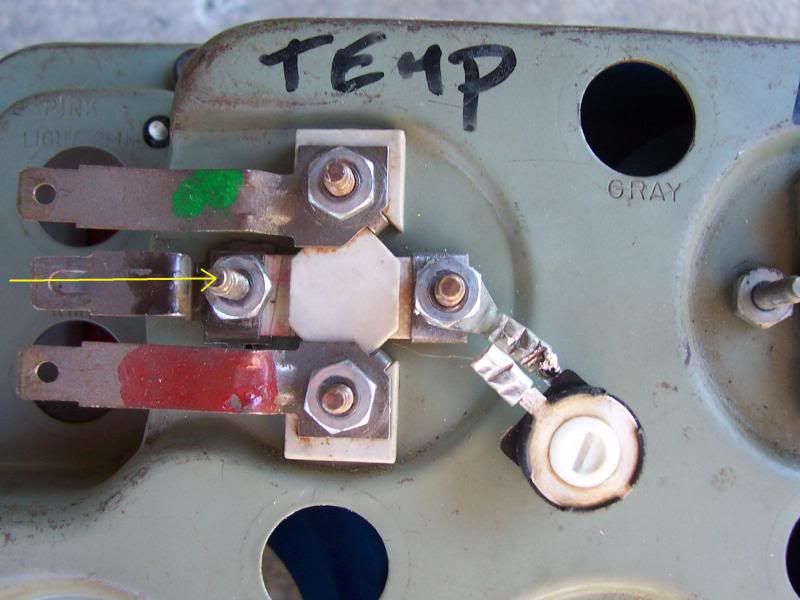
Last edited by ...Roger...; Apr 23, 2011 at 06:55 PM.
Team Owner


Joined: Sep 2006
Posts: 31,301
Likes: 4,389
From: Westminster Maryland
Thanks Roger and Ernie.
I made a little fuel sender tester from information written by John Hinkley. It involved some sort of 'pot' I bought at the electronics store. It allows you to test the full range of the gauge to see if the problem is the sender or not.
I'm REALLY bad at all things electrical because I'm color blind. I have to make tags for everything and my wife helps me put them on the wires.
Regards,
Alan
Former Vendor
Joined: Aug 2006
Posts: 76,656
Likes: 1,853
From: Jeffersonville Indiana 812-288-7103
St. Jude Donor '08-'09-'10-'11-'12-'13-'14-'15
Alan.. you saying your passing up on a ***** Willcox plate.. actually Johns tester is a linear pot.. so your good.. and you can use this other gauges. As you can see the temp gauges have a wider range than the fuel or oil pressure... so the adjustable pot needs be around 0-250 ohms.
Roger... its easy for you and me.... but some may not understand what we are doing or how it affects the gauge... and most wouldn't ever think of doing this.
If I was a betting man I'd say that the green wire has a little resistor in place somewhere before it hits the gauge.
actually Johns tester is a linear pot.. so your good.. and you can use this other gauges. As you can see the temp gauges have a wider range than the fuel or oil pressure... so the adjustable pot needs be around 0-250 ohms. Roger... its easy for you and me.... but some may not understand what we are doing or how it affects the gauge... and most wouldn't ever think of doing this.
If I was a betting man I'd say that the green wire has a little resistor in place somewhere before it hits the gauge.
Last edited by Willcox Corvette; Apr 23, 2011 at 08:03 PM.
Thread Starter
Instructor
Joined: Feb 2008
Posts: 211
Likes: 2
Okay.. have not heard from Roger yet but am going to get a head start on the "Florida Snake" tester Roger spoke of earlier on this thread. Roger said hook it up to the alt and the green wire. So now it seems like we are bypassing the sending unit altogether. Where on the alternator do I hook the clip and how will the alternator convey a heat temp to a water temp gauge?

Melting Slicks


Joined: Apr 2010
Posts: 2,796
Likes: 1,197
From: Canberra Australia
2025 C3 of the Year Finalist - Modified
This is the one I built following Rogers previous thread.

works great and never gets hot.
Entire item shrink wrapped before install.
Craig
works great and never gets hot.
Entire item shrink wrapped before install.
Craig
Race Director
Joined: May 2006
Posts: 16,528
Likes: 53
From: Dayton, Ohio
IMO the simplest and most direct is to input an ohms signal and see if the gauge reads that ohms signal correctly (needle at the correct temp).
The little tester in my post #12 is easy to make,you don't have to have the alligator clip and the male spade.
As Ernie said in his post the gauge is showing good in that the needle will go extreme both directions-this usually is the end BUT you said your mechanic changed the resistor. The way I read your post I'm thinking he changed the resistor across the back of the gauge,could be good or could be bad depending on what the needle shows when you install the little tester from post 12.
If after you install the tester your needle reads close to 210 then all we need to do is find you good sender.
The little tester in my post #12 is easy to make,you don't have to have the alligator clip and the male spade.
As Ernie said in his post the gauge is showing good in that the needle will go extreme both directions-this usually is the end BUT you said your mechanic changed the resistor. The way I read your post I'm thinking he changed the resistor across the back of the gauge,could be good or could be bad depending on what the needle shows when you install the little tester from post 12.
If after you install the tester your needle reads close to 210 then all we need to do is find you good sender.
Okay.. have not heard from Roger yet but am going to get a head start on the "Florida Snake" tester Roger spoke of earlier on this thread. Roger said hook it up to the alt and the green wire. So now it seems like we are bypassing the sending unit altogether. Where on the alternator do I hook the clip and how will the alternator convey a heat temp to a water temp gauge?
The alligator clip goes to a solid ground (the alternator case is a good source of ground).
We are bypassing the sender.
Team Owner
Joined: Sep 2006
Posts: 31,301
Likes: 4,389
From: Westminster Maryland
Hi Ernie,
No, I'm not passing up on your offer. I was just relating the very little experience I've had with things electrical.
Fortunately, the electrical systems in my car were in good shape. All I've had to do is replace the engine harness, (I think they take the most beating because of the heat and oily environment), and have the clock and wiper motor repaired.
Again, thanks for your offer!!
Regards,
Alan
Thread Starter
Instructor
Joined: Feb 2008
Posts: 211
Likes: 2
Alright I made the tester and did the test. Moved to about half way between the 100* (first far left) and the second mark. If I had to guess I would say maybe 125* or 135*.
Former Vendor
Joined: Aug 2006
Posts: 76,656
Likes: 1,853
From: Jeffersonville Indiana 812-288-7103
St. Jude Donor '08-'09-'10-'11-'12-'13-'14-'15
Yep.. something is wrong.. 78 ohms should put him on 210. He needs to find that resistor.. remove it.. and then test again. But Roger.. why do you think he put it on the back of the gauge.. I'm still thinking it may be in line. I don't think most mechanics would go to the gauge before trying it inline.
220 ohms to make 100 on the face.
109 ohms to make the first mark.
79 ohms to make 210 mark.
65 ohms to make the mark just after 210
51 ohms to make 250 mark..
220 ohms to make 100 on the face.
109 ohms to make the first mark.
79 ohms to make 210 mark.
65 ohms to make the mark just after 210
51 ohms to make 250 mark..
Thread Starter
Instructor
Joined: Feb 2008
Posts: 211
Likes: 2
That's what he said he did so now what does he (or I) do next. So far as I understand at this point, new gauge is working, sender may or may not be working but if it is working it's not compatible with the resistor on the back of the new gauge. I hate to sound like a broken record and helpless but....what next. I am going to talk to my mechanic monday with all of my new found knowledge.
Race Director
Joined: May 2006
Posts: 16,528
Likes: 53
From: Dayton, Ohio
Sharks quote from OP:
[ Replaced the sending unit which he said didn't match temp gauge. Changed the resistor 'cause he said wasn't measuring the engine temp correctly.]
Ernie,as you know (but others might not) adding ANY resistor in the green wire can ONLY make the gauge read COLDER,never hotter.
Going from past experience this mech was fighting what we all fight and that is senders that already read TOO cold.